Auto-Closing Stacking Drawers for 20mm V-Rail Framed 3D Printers
by Icelandian in Workshop > 3D Printing
7850 Views, 52 Favorites, 0 Comments
Auto-Closing Stacking Drawers for 20mm V-Rail Framed 3D Printers
UPDATE: 07 April 2021:
STL files posted, see last step.
PROJECT SUMMARY:
This project was inspired by:
- Instructables Member Zackfreedman and his Multicolored Organizer Project
- Thingiverse member Olga Pavlova and her Stacking Drawer Design
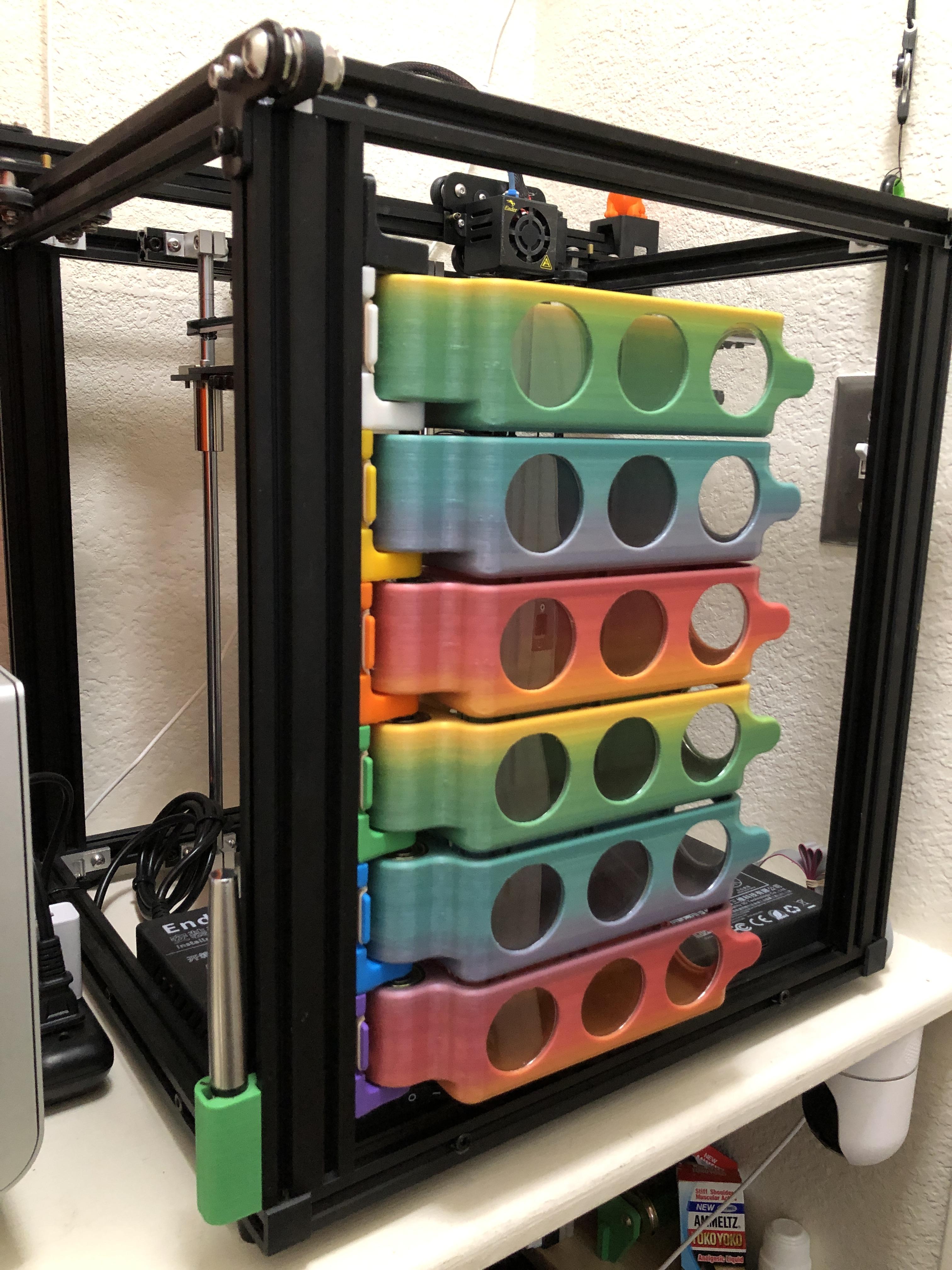
My mashup of those two ideas aims to create ample and organized space for small items all within easy to reach, easy to access, and easy to identify storage drawers intended for 3D printers using 20mm V-Rail as part of their frame like my Creality Ender 5 Pro.
Only two items must be purchased (skateboard wheel bearings and clear plastic rounds), while the rest of the parts are created by the 3D printer itself or should be on hand (like rubber bands). Auto-Closing is accomplished by a standard size rubber band and attachment to the V-Rail is through standard 5mm T-Nuts.
This Instructable is an entry in the Simple Machines Contest. Please vote if you like it.
(This auto-closing drawer design is an example of a simple machine featuring Elastic Energy, Torque, and Rotational Work. It best aligns with a "Wheel & Axle" simple machine per the contest guidelines.)
TABLE OF CONTENTS:
Project Summary
Supplies
Step 1: Requirements & Desirements
Step 2: Design
Step 3: Illustrated Parts List & Features
Step 4: 3D Printing
Step 5: Post Processing the 3D Printed Parts
Step 6: Build Step I: Gather all Parts
Step 7: Build Step II: Install Windows
Step 8: Build Step III: Mount Base to V-Rail
Step 9: Build Step IV: Install Pivot Pin
Step 10: Build Step V: Install First Bearing
Step 11: Build Step VI: Install Drawer
Step 12: Build Step VII: Install Second Bearing
Step 13: Build Step VIII: Attach Rubber Band
Step 14: Build Step XIV: Repeat Steps I-VIII for Next Level
Step 15: Validation
Step 16: FINISHED
Supplies
MATERIALS:
- Skateboard Bearings (608ZZ) (Quantity 2 Per Drawer)
- 40mm Clear Acrylic Rounds (Quantity 4 Per Drawer)
- 5mm Panhead Screws & T-Nuts (Quantity 2 EA Per Drawer)
- Rubber Bands (Size #32 - 3" X 1/8") (Quantity 1 Per Drawer)
TOOLS:
- 3D Printer
- Allen Wrench For The 5mm Screws
- Standard Shop/Hand Tools For Post Processing The 3D Prints (Supports Are Required)
SOFTWARE:
- Autodesk's Fusion 360 (Used To Create The Design)
- Ultimaker's Cura Or Other Slicer (For Slicing The Files To Your Specific Printer)
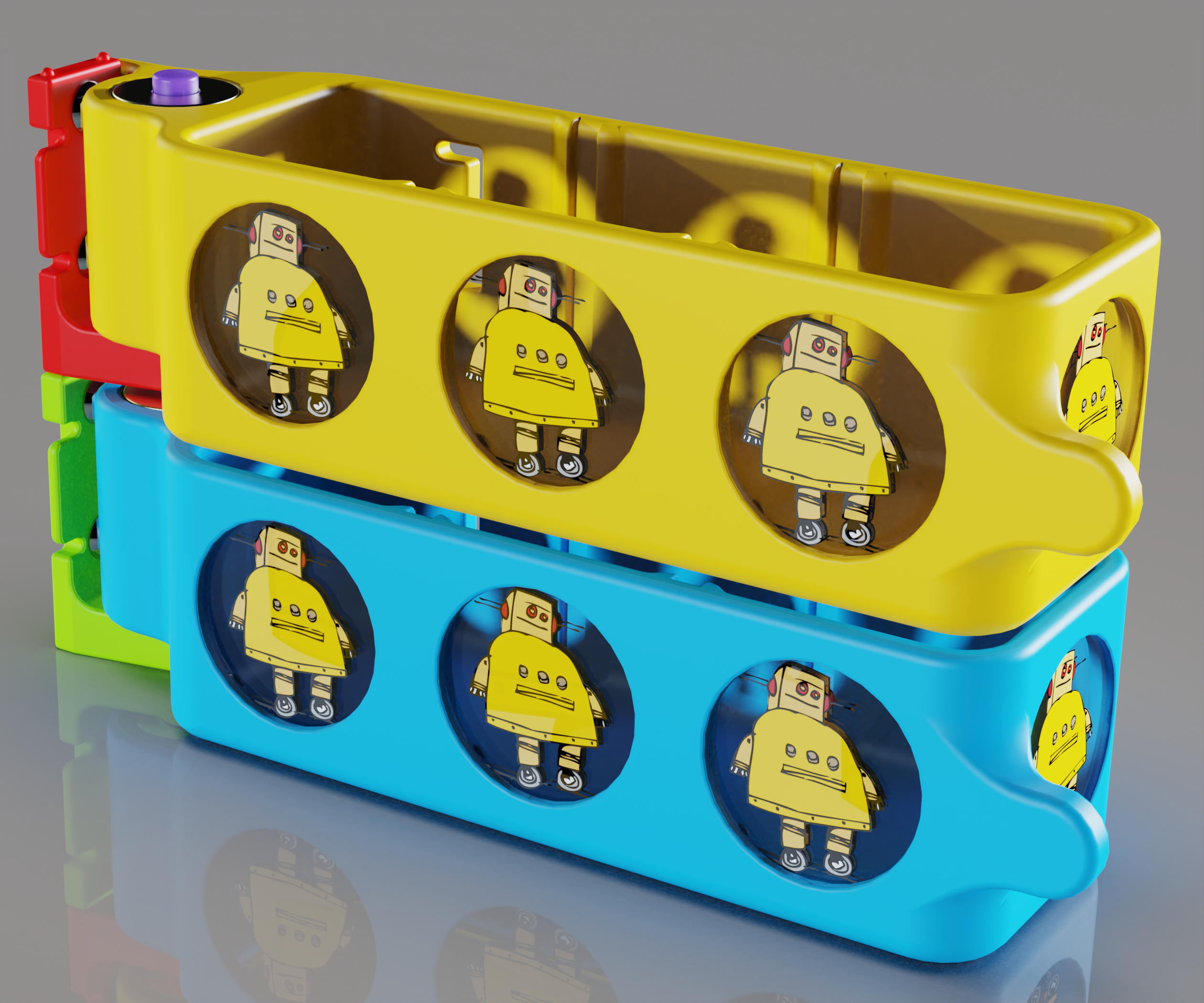
- Luxion's Keyshot (Used To Create Realistic Renders like the image with the Instructable Trademarked Logo)
- Corel's Video Studio (Used to Create Short Time-Lapse Videos From Still Shots)
- Adobe's Photoshop (For Photo Editing)
- Microsoft's PowerPoint (For Image Labeling)
Requirements & Desirements

Here's a list of requirements and desirements in no specific order:
- Drawers can not impede the operation of or normal access to the printer
- Drawers should have a feature to keep them closed
- Since they stack, having a feature to see what's inside would be desirable
- Minimize need for purchase parts
- Maximize number of 3D printed parts
- Minimize cost
- Use a variety of filament colors to maximize visual appeal (or use for categorization, ex. Blue Drawer = Q-Tips)
- Include a feature to temporarily hold a drawer in the open position
- Size the drawer such that the design can fit on a variety of printers (not be specific to only my printer)
- Size the drawer's internal space to fit some of the most common tools frequently needed while 3D printing
- Make the design compatible to be either Left or Right Handed
Design
I continue to enjoy working with Autodesk's Fusion 360 for all my personal design projects. (I wish I could use it for work, but am still stuck with CREO). Even with the great value of the free hobbyist license, I use it so much and wanted some of the extra features that come with a full license I recently made the purchase. (And I can honestly say its well worth the cost and I don't think I've ever spent more than $20 on software, so it was a big leap of faith for me.) It even has an icon at the bottom "Click to Chat with Expert" if you ever get stuck or just have a question. How cool is that?
I won't go into a lot of detail on the design process itself other than to point out a few Fusion 360 features that really help speed the process along.
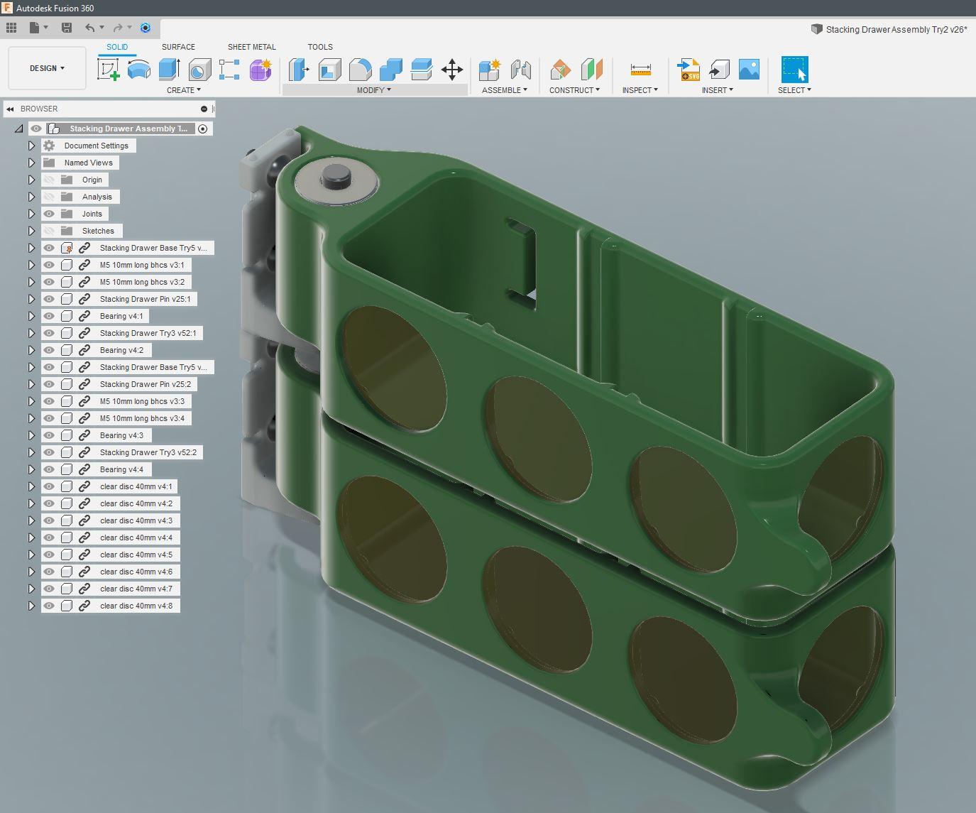
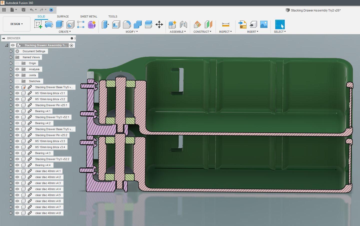
First is "Section Analysis". In only 2 clicks, you can create a virtual slice through a part (or assembly as shown in the second image above). This is extremely valuable to be able to quickly visualize how parts will come together and be able to find issues before wasting time printing large parts only to realize the issue with the real hardware.
Second, is the simple manner in which parts are assembled. It is super intuitive and easy to assign joints and at the same time specify freedom of movement between them. And after assembling all the parts in your design you can run a quick interference analysis to check for overlap problems.
TIP: A great resource is Mcmaster.com, which allows anyone to download 3d models of common hardware to save you the time to model them from scratch (like the screws shown in the above images.)
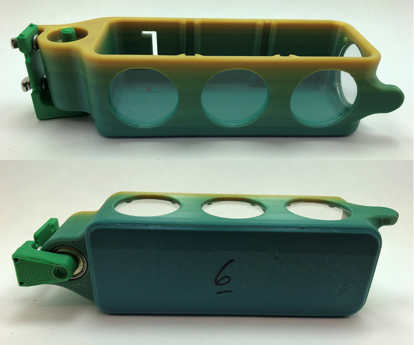
Illustrated Parts List & Features
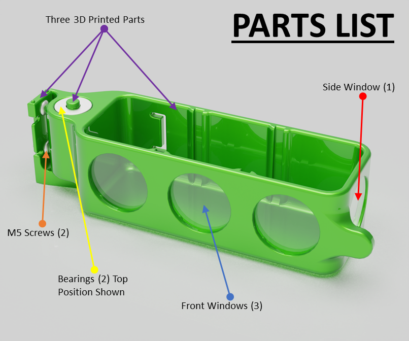
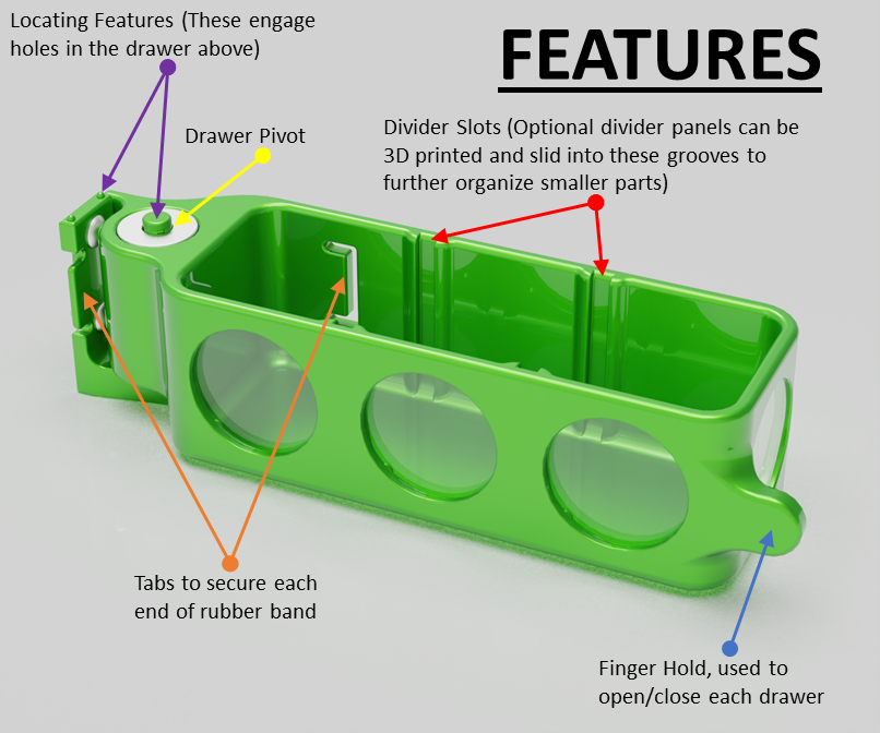
Please see images above that detail the individual parts and features of each drawer.
TERMINOLOGY: Throughout the Instructable I'll refer to the 3D printed parts as:
- The Drawer
- The Base
- The Pivot Pin
NOTE1: The M5 screws mate to the T-Nuts that engage the V-Rail.
NOTE2: The V-Rail used on the Ender 5 printer is called 2040 rail. Its 20mm series extruded rail, but this particular size is called 2040 to denote one dimension is 20mm and the other is 40mm.
3D Printing
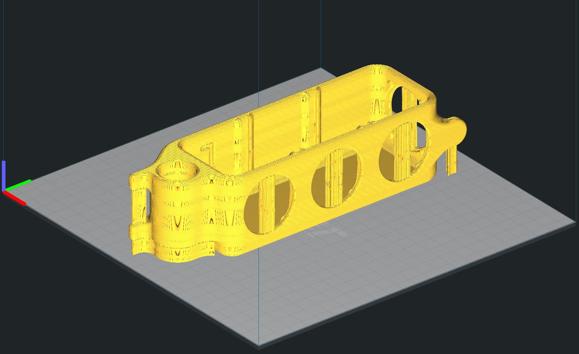
All parts are printed in the same orientation as they are assembled on the printer. Shown above is the main drawer after slicing in Cura to show where the supports are required. The settings are as follow:
DRAWER:
- 0.16mm layers (more or less is fine, it will only increase/decrease print time)
- 30% infill (More is better, but will drastically increase print time)
- No build plate adhesion (due to the large surface area of the bottom of the drawer)
- Supports (choose everywhere, and adjust overhang angle to roughly get whats shown above)
BASE & PIVOT PIN:
- 0.16mm layers (less if you can)
- 100% infill
- Rafts (due to the high height/base area ratio)
- No supports needed
NOTE: Print time with these settings was just under 24 hours per drawer.
Post Processing the 3D Printed Parts
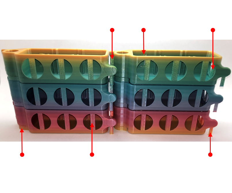
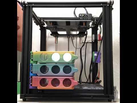
This is an image of all 6 drawers pulled directly off the printer before removing the support material. The red arrows show each different support position that needs to be removed. The support material is set to print at a low infill (10% or lower) so it easily breaks away. But use a sharp Xacto knife to clean the areas where the support was touching the main part. Especially around the window openings as its a tight fit and even a tiny bump will make installing the windows harder or impossible.
NOTE: I did not plan on the rainbow filament ending almost perfectly at the third drawer. That was simple luck. I think I set them up for that picture with the first print at lower left going up, then the fourth print was the lower right. See ZachFreedman's instructable for different methods of printing with rainbow filament. "Always go with Galactic Brain!"
Build Step I: Gather All Parts
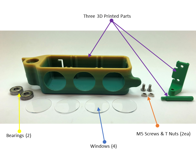
See image above for all the parts you'll need for each drawer. (Forgot to include a rubber band in the picture.)
Build Step II - Install Windows
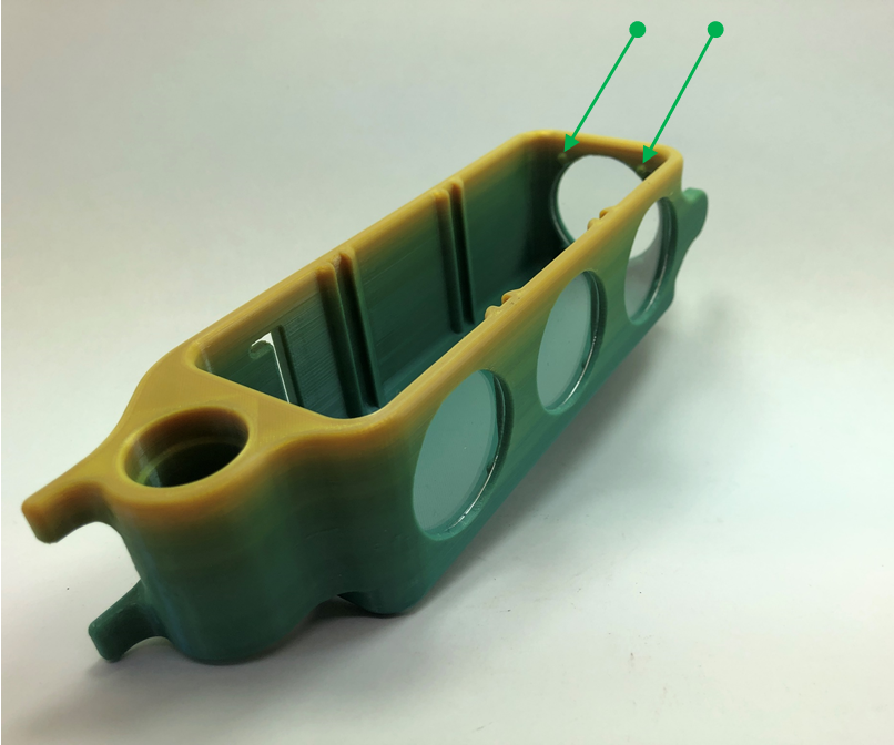
There are four small nubs integral to the drawer for each window. The upper two indicated by green arrows in the image above are for the side window location. When inserting the clear discs, angle it so it engages any two nubs, then bring the opposite side of the window in towards the drawer's window opening and press tightly until it snaps in place. (Its a nice satisfying "CLICK", so you'll know when its in!)
NOTE: Depending on your printer's ability to print these small features, you may need to to simply add a dab of glue if you are unable to get them to print correctly.
Build Step III - Mount Base to V-Rail
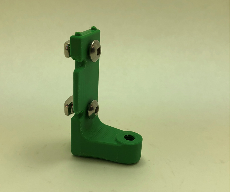
Loosely install the T Nuts into the first drawer base as shown in the image above.
Position and secure the base onto your V-Rail paying attention to ensure it is perfectly aligned to the rail vertically. If it is off, when you go to add the drawer above, it will cause that subsequent drawer to be misaligned.
Also, based on the number of drawers you are adding to your printer, you need to assess the vertical position of the first base if you are concerned with equally spacing the upper and lower gaps after all drawers are installed. For my printer, I simply started the first base so it just cleared the printer's lower electronics housing cover with about 3mm of clearance.
Build Step IV - Install the Pivot Pin
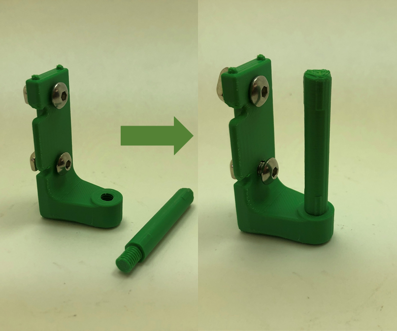
Screw the pivot pin into the base as shown above. It should go in by hand. If its too tight, try reprinting at a finer detail level.
NOTE1: This step is done after the base is on the printer. (The image above, as well as subsequent images, are just for reference.)
NOTE2: The reason this is a separate part is to allow easy access to tighten the allen screws. If the pivot pin was integrated into the base part and printed as one (which I tried) you either need a special ball-end allen wrench or add holes into the pivot pin to allow the tool to go completely though it (tried that too). This was an easy solution to the problem even though it added a separate part which I try to avoid if at all possible. (Plus being able to print threads is so Cool! And really only possible with Fusion 360.)
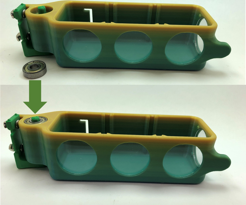
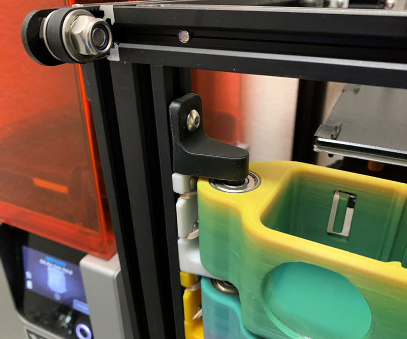
Build Step V - Install First Bearing
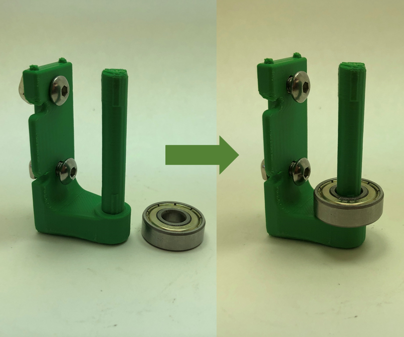
Slide the first bearing over the pivot pin and ensure its inner race is fully in contact with the raised mating surface of the base part.
Build Step VI - Install the Drawer
Slide the drawer over the pivot pin until its starts to engage the outer diameter of the lower bearing. Press firmly to seat the drawer onto the bearing. A feature in the drawer will set the insertion height, so simply push until it stops.
NOTE: Its best to be able to immediately perform the next build step, so have the second bearing ready prior to starting this step.
Build Step VII - Install Second Bearing
Slide the second bearing over the pivot pin while supporting the drawer horizontally to prevent putting stress on the pivot pin. As with the first bearing, there are features inside the drawer that set the height, so press the bearing in until it stops.
NOTE: Again, its best to be able to immediately perform the next build step, so have the next level's base part ready prior to starting this step.
Build Step VIII - Attach Rubber Band
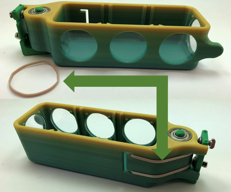
This is probably the hardest part, especially if have large fingers and no nails. Route the rubber band as shown trying to keep it free of twists.
NOTE1: You can do this step now or once all drawers are installed. But if you wait till later you'll have less room to work with and will likely need tweezers to grab and route one end after attaching the other side of the rubber band.
NOTE2: I tried starting the rubber band in both places first, but it was not particularly easier one way or the other.
Build Step XIV - Repeat Steps I-VIII for Next Level
Start with the next level's drawer by ensuring the base part fully mates with the two nubs of the lower base and the protruding end of the lower level pivot pin. This is important as it is the final step in fully securing the lower level drawer. (Refer to the purple arrows in the second image on Step 3.
If you are at the last drawer, use the Base Cap part to secure the last level as shown in the image above (its the black part at the top).
Validation
Revisiting the Requirements from step 1:
- Drawers can not impede the operation of or normal access to the printer
- Drawers should have a feature to keep them closed
- Since they stack, having a feature to see what's inside would be desirable
- Minimize need for purchase parts
- Maximize number of 3D printed parts
- Minimize cost
- Use a variety of filament colors to maximize visual appeal (or use for categorization, ex. Blue Drawer = Q-Tips)
- Include a feature to temporarily hold a drawer in the open position
- Size the drawer such that the design can fit on a variety of printers (not be specific to only my printer)
- Size the drawer's internal space to fit some of the most common tools frequently needed while 3D printing
-
Make the design compatible to be either Left or Right Handed
I think I met them all except a few:
#8. But, I don't think its really needed. (Though time using the drawers will tell.)
#10. A few tools were too long to fit, so each drawer could be a bit wider, but that would risk violating #9.
NOTE: While I only modeled the design to fit a "Left - Hand" column, in just a few minutes I can easily mirror the Drawer and Base part for a "Right-Hand" column using Fusion 360.
FINISHED
All done! Thanks for taking the time to read through my Instructable. Please send me any questions or comments you might have. I try to answer them all. Stay safe and healthy! Happy 3D Printing!
Thanks again to the inspirations - Zackfreedman and Olga Pavlova. This was a fun (though very time consuming) project. As always I'll continue to update with any findings and/or improvements.
NOTE: At this time I need to hold off on posting the .STL files. There are a few minor things I want to fix.
And finally; remember - This Instructable is an entry in the Simple Machines Contest. Please vote if you like it.
STL & Fusion360 Files
Since the original posting, I've added an adjustment feature to the two tabs on the drawer part. The same M5 screws in these holes will adjust the angle at which the drawer is set to in the closed position.
There are two drawer files. With and without windows.
I also included the native Fusion 360 file if anyone wants to modify it. (Its the .txt file - change file extension back to .f3z.)