Audio Responsive RGB Feathered Scarf
by ploopploop in Craft > Fashion
1205 Views, 6 Favorites, 0 Comments
Audio Responsive RGB Feathered Scarf
)
Most people enjoy going to parties and those that do also do enjoy presenting themselves in a fashionable way, at least I know I do! In this day and age technology is quite advanced. Entertainment in general has evolved rapidly, so why not take fashion along with it?
In this instructable we will be creating an audio responsive RGB feathered scarf. This scarf will be tuned for mainly concerts and festivals (places with loud music in general), but I will also explain how you can tune up or down the sensitivity so that you can even get it to work during a meeting with your colleagues in a quite silent environment. They might not be too fond of it though...
This project also varies in pricing range depending on your budget. You can go all out if you got money to spare, but even on a tight budget you can create quite an amazing scarf for yourself! This is due to most components being pretty basic.
Also a few tips before you start with this:
At least read through the steps to understand how the parts will be used.
Always test at every step! I can't stress this enough. You don't want to discover that something broke at step 3 when you are at step 6 for example.
Supplies
This is a list of items that you will need.
ARGB led strip of 1 meter (60 leds per meter)
If you want more than 60 leds per meter or a longer size then you will need a better power source than what I show in this example. This setup can only power up to 18 watts.
Arduino casing
Any casing is fine as long as you can access the connections.
A simple shoulderbag, you will be making some holes in here!
I do suggest getting an old bag for this.
A white feathered scarf
White is better than colored since the RGB colors will be reflected better on it.
Audio cable 10M
A thickness of 0,5mm is more than plenty. You will need at least 2 meters.
Sparkfun Audio Module
Do note that if you can't find the one with header pins on it that you will need to order header pins separately and solder them on it.
Resistors
These are used to tune the sensitivity
A 3A 5V power bank
Any 3A 5V power bank is fine, so if you want more or less mAh, go for it!
Vinyl gloves (optional)
It is optional but strongly recommended since you will be working with super glue.
You will also need a computer that is able to connect to your Arduino in order to upload the coding logic.
Step 1: Connecting Led Strip
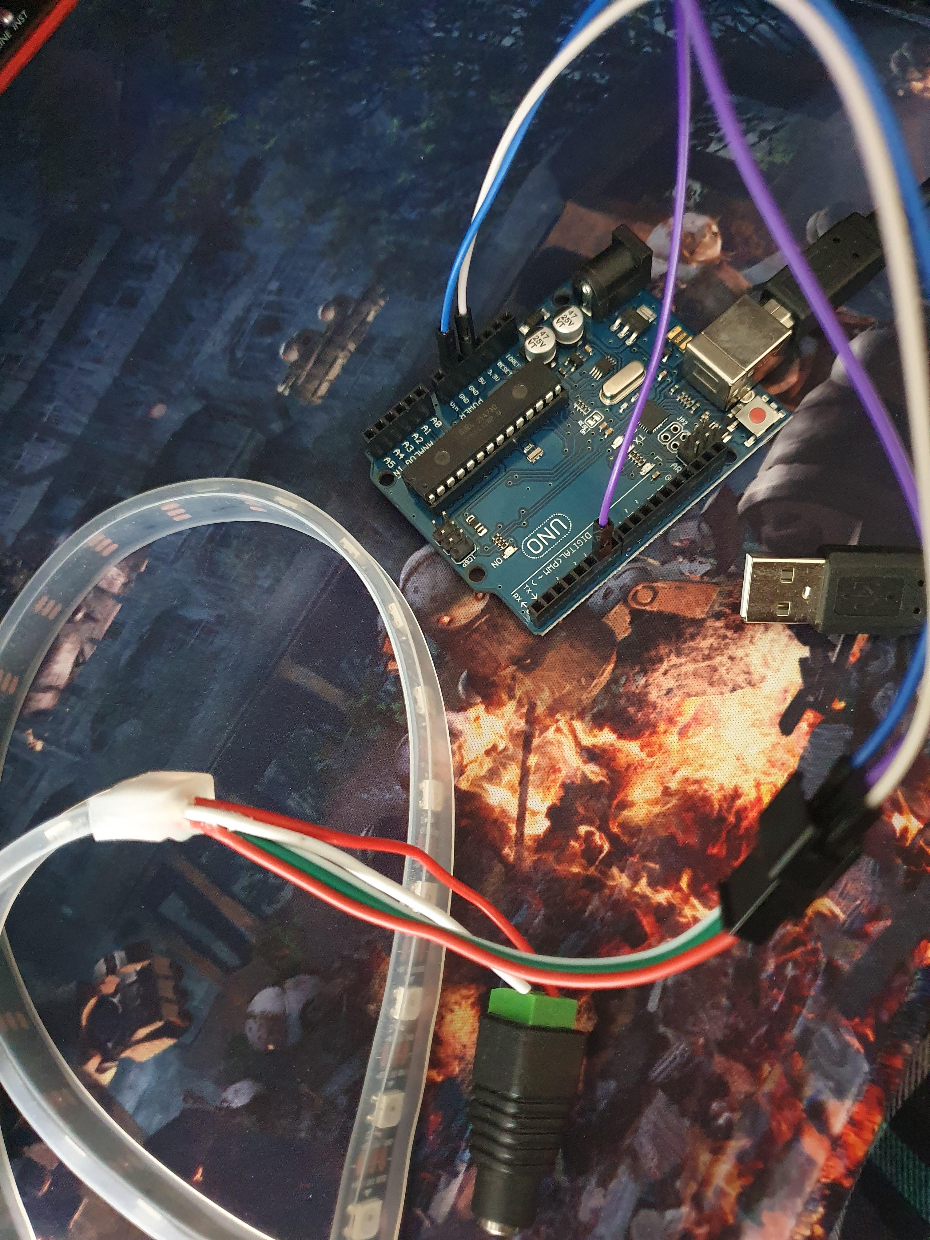
Before we can do anything, make sure to have the Arduino IDE installed on your system. You can find this on their website.
Once you have that it is important to test your parts, so we will start with the nicest looking part, the led strip.
Your led strip has 3 rows of connections with most likely 5 cables. The rows are 5V, DIN, GND. 5V and GND might have 2 cables each depending on the ledstrip. You will need to attach only 3 out of the 5 unless your led strip requires more power. For this example we will assume that your setup is similar to mine.
Connect the cable from the GND from the led strip to a jumper cable (can be male to male or female to male depending on the led strip design). Connect that cable to your Arduino's GND. It is best practise to do this first so that you ground your led strip.
Once that has been done you can connect the 5V to your Arduino's 5V and the DIN to pwm pin 6 (any pwm pin will suffice).
Congratulations, with this you have connected your led strip to your arduino!
Step 2: Testing the Led Strip
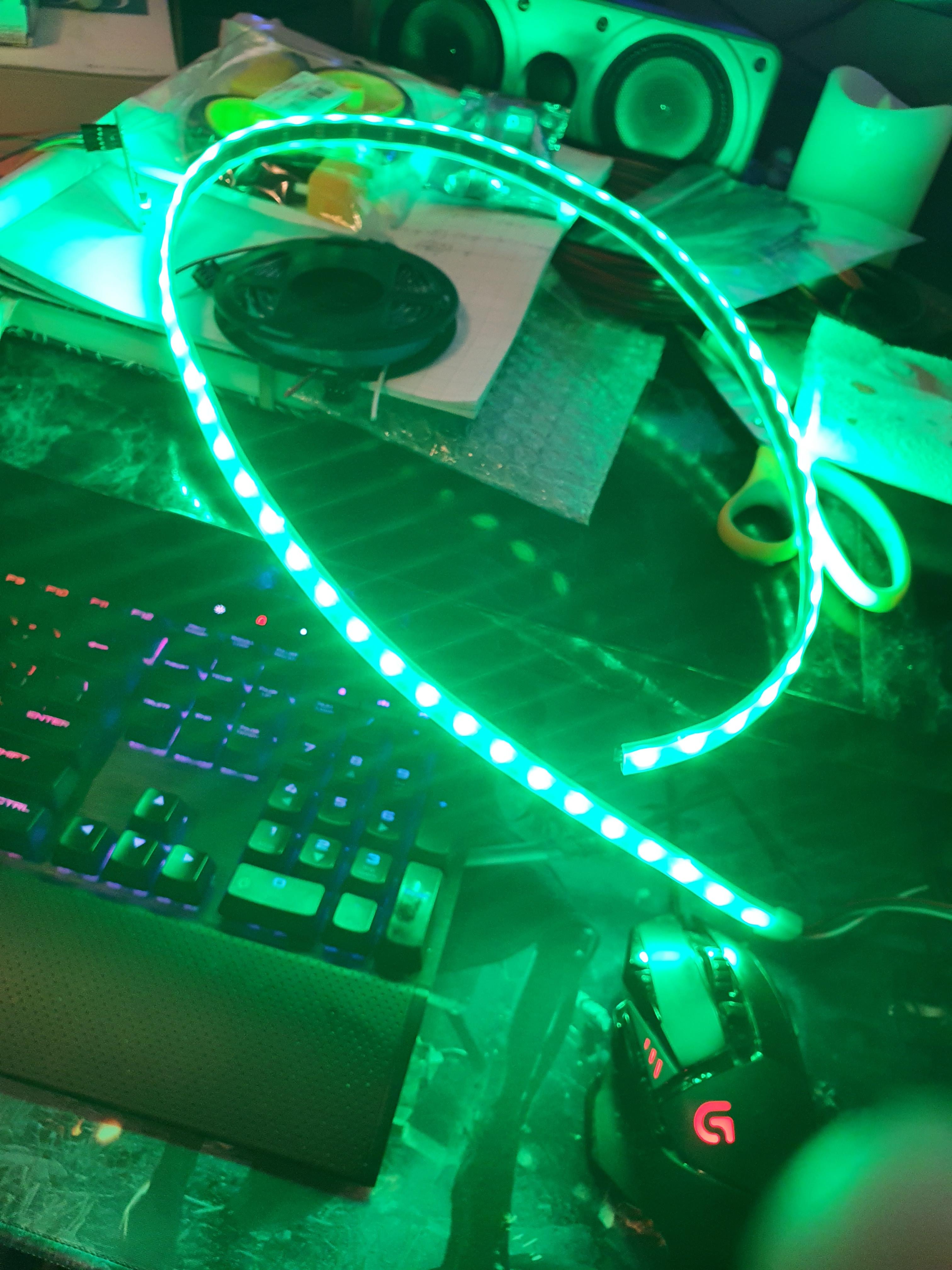
Since the led strip is the most important part it is mandatory to test if it works first. I unfortunately have had the experience of receiving faulty products so always double check that your products work properly.
Connect your Arduino to your pc and launch the IDE. Download the library called FastLED. We will be using this for the animations.
Make a new file and paste the following code into it.
#include <FastLED.h>

#define LED_PIN     6
#define NUM_LEDS    60

CRGB leds[NUM_LEDS];

void setup() {
  FastLED.addLeds<WS2812, LED_PIN, GRB>(leds, NUM_LEDS);
}

void loop() {
  for(int i = 0; i < NUM_LEDS; i++){
    leds[i] = CHSV(100, 255, 255);
  }
  FastLED.show();

  delay(100);
}
Verify and upload this code to your Arduino. If the led strip is working properly all the leds should light up with a green ish color. See the image above for similar results.
As you might be able to tell, the color work with HSV inputs. So if you want to use specific colors you will have to change the HSV values. If you want to learn more about HSV in general I do recommend to read this article about it and experiment with the sliders.
Step 3: Hooking Up the Audio Module
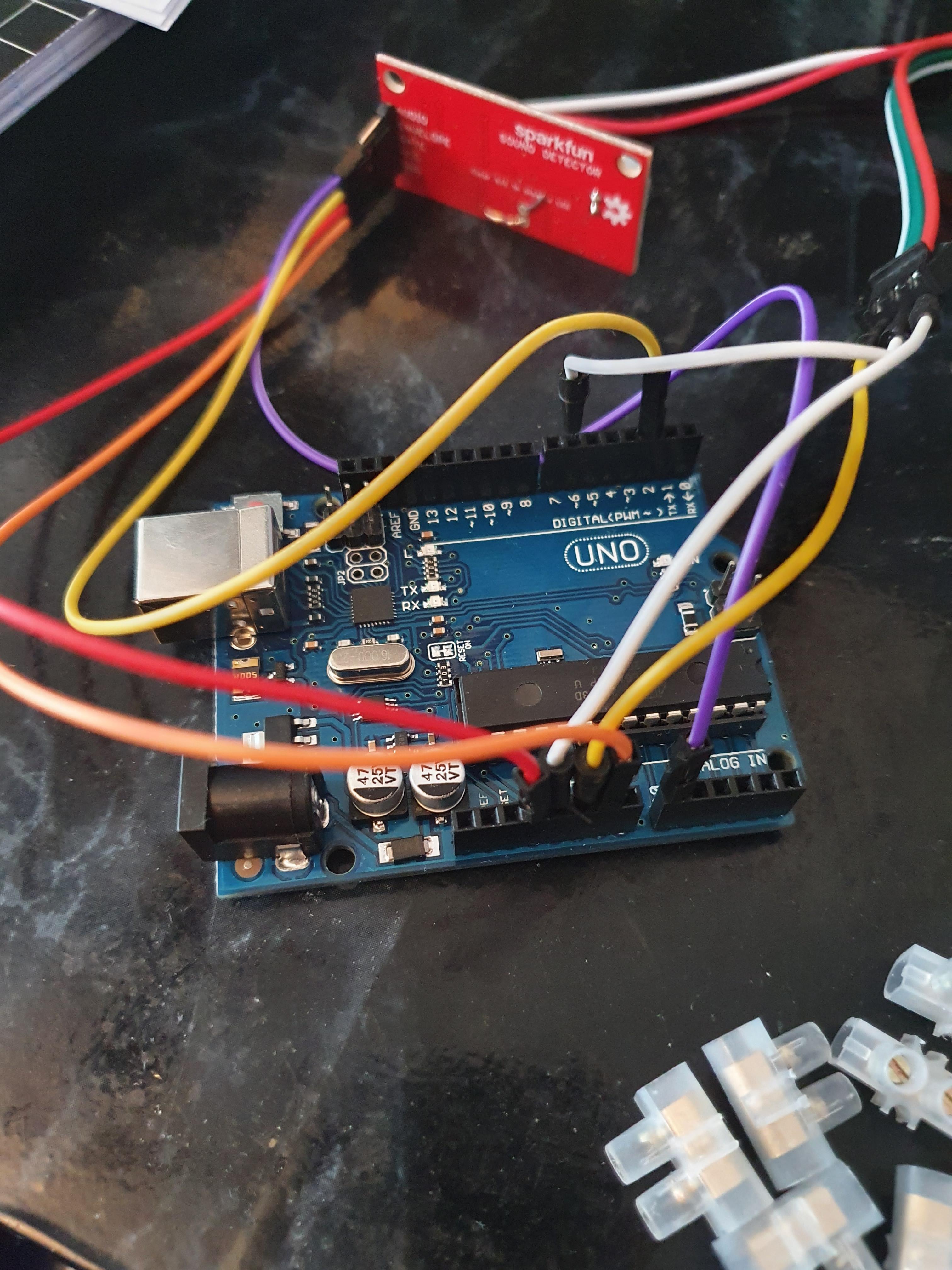
The audio module is a tiny but complex component. It has 5 connections from which each connection has its own significance.
The connections are as follow:
- Audio
- Envelope
- Gate
- VCC
- GND
Start by connecting your GND to the GND from the Arduino.
VCC will be our 3.5V connection to the Arduino. You can also connect it to 5V through a bread/perf board if you want, but this will give higher valued readings. I suggest doing that if you have experience with this. Otherwise it is a lot cleaner to use the 3.5V connection for VCC since we won't be needing a breadboard.
Then we have 3 connections remaining. These 3 basically give us various reading. Does it detect a peak? How loud is the sound? What is the frequency of the sound? We will only be using the first 2. This is Gate and Envelope. We will connect Envelope to A0 and Gate to pin 2.
Now the second part of this step; fine tuning. On the module there is the R17 and R3. R3 is used to lower the gain whereas R17 is used to up the gain. In this project I only used R17 with a 100K resistor to up the gain by 40dB. This is in order to be able to test in not so noisy environments. For a full breakdown of the values I do recommend skipping to the configuration part on the website of sparkfun. You should have enough resistors to play with the gain depending on your needs. You can insert the resistor through the holes and bend the pins on the other side. Or if you want to be fancy and clean you can solder it. Both work.
In order to properly continue with this instructable make sure that you have a 100K resistor attached to it. You can use apps like Electrodoc for Android in order to read how strong the resistor is. You can also use charts online.
Step 4: Audio Responsive RGB!
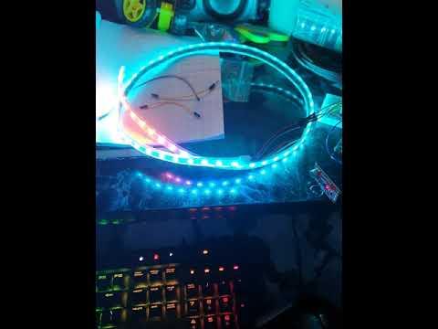
Now that everything is hooked and connected it is finally time to delve into the good stuff, the fun stuff! We are going to animate the led strip. Do note that we are doing it in this order so that components can be easily replaced if faulty. At the very last step we will finalize the project.
This coding part can be fully customized with how you want it. I will give you my basic code with some explanations to it so that you can create your own variations.
First of all, there is a second library that you will be needing. It is called CircularBuffer. This allows us to iterate rapidly through color cycles by implementing smart algorithms. There might be better methods out there, this is just as far as my knowledge goes for programming in Arduino, so feel free to differ.
In this sample we use 4 different color cycles. Every 20 seconds our Arduino picks the next cycle and at the end it returns back to the first cycle.
The cycles are defined as LedCombis. Each has its own unique effect that might be comparable to the others. With our own variables we are able to do some interesting things.
#include <CircularBuffer.h>
#include <FastLED.h>

// LED variables
#define LED_PIN     6  // pin used for the led strip DIN
#define NUM_LEDS    60 // amount of leds the strip has
CRGB leds[NUM_LEDS];

// MIC variables
#define PIN_GATE_IN   2  // pin used for gate
#define IRQ_GATE_IN   0
#define PIN_ANALOG_IN A0 // Analog in used

// User defined variables
bool on = true; // used for flipping the colors basically
int value = 0; // hue value
int cycle = 0; // keep track of the current cycle
int cycleTime = 20000; // the duration of a cycle in milliseconds
int scrollVal = 0; // used for scroll animations
unsigned long timer = 0; // has to be unsigned

CircularBuffer<int,60> buffer;

// required for sound module
void soundISR()
{
  int pin_val;

  pin_val = digitalRead(PIN_GATE_IN);
}

void setup() {
  pinMode(PIN_GATE_IN, INPUT);
  attachInterrupt(IRQ_GATE_IN, soundISR, CHANGE);

  FastLED.addLeds<WS2812, LED_PIN, GRB>(leds, NUM_LEDS);
}

// update cycle every 20 seconds and run the function for the cycle
void loop()
{
  if (millis() - timer > cycleTime) {
    timer = millis();
    cycle += 1;
  }

  if (cycle > 3)
  {
    cycle = 0;
  }

  switch(cycle)
  {
    case 0:
      LedCombiA();
      break;
    case 1:
      LedCombiB();
      break;
    case 2:
      LedCombiC();
      break;
    case 3:
      LedCombiD();
      break;
  }
}

// half circle quite fast
void LedCombiA()
{
  SetValue(10);
  scrollVal ++;<br>  if(scrollVal > 59){
    scrollVal = 0;
    leds[59] = 0;
  }
  leds[scrollVal] = CHSV(100 - value, 255, 255);

  if (scrollVal - 2 >= 0)
    leds[scrollVal - 2] = 0;

  if (58-(scrollVal) >= 0)
    leds[58-(scrollVal)] = CHSV(value, 255, 255);

  if (58-(scrollVal - 2) <= 59)
    leds[58-(scrollVal - 2)] = 0;
  FastLED.show();
  delay(5);
}

// 6 responsive sections with 10 leds each
void LedCombiB()
{
  SetValue(4);
  for(int i = 10 - 1; i >= 0; i--)
  {
    if (i == 0)
    {
      leds[i] = CHSV(100 + value, 255, 255);
      leds[i+10] = CHSV(100 + value, 255, 255);
      leds[i+20] = CHSV(100 + value, 255, 255);
      leds[i+30] = CHSV(100 + value, 255, 255);
      leds[i+40] = CHSV(100 + value, 255, 255);
      leds[i+50] = CHSV(100 + value, 255, 255);
    }
    if (i != 0)
    {
      leds[i] = leds[i-1];
      leds[i+10] = leds[i+10-1];
      leds[i+20] = leds[i+20-1];
      leds[i+30] = leds[i+30-1];
      leds[i+40] = leds[i+40-1];
      leds[i+50] = leds[i+50-1];
    }

    FastLED.show();
  }
}

// cycle between 2 main colors based on volume for hue
void LedCombiC()
{
  if (on) {
    for(int i = 0; i < NUM_LEDS; i++)
    {
      SetValue(1);

      leds[i] = CHSV(value, 255, 255);

      if (i == NUM_LEDS - 1)
      {
        on = false;
      }
      delay(5);
      FastLED.show();
    }
  }

  if (!on)
  {
    for(int i = 0; i < NUM_LEDS; i++)
    {
      SetValue(1);

      leds[i] = CHSV(255 - value, 255, 255);

      if (i == NUM_LEDS - 1)
      {
        on = true;
      }
      delay(5);
      FastLED.show();
    }
  }
}

// super fast circular effect
void LedCombiD()
{
  SetValue(2);
  buffer.push(value);
  for(int i = 0; i < NUM_LEDS; i++){
    leds[i] = CHSV(50 + buffer[i], 255, 255);
  }
  FastLED.show();
}

// assign a value that will be used in hue calculations
void SetValue (float mod)
{
  value = analogRead(PIN_ANALOG_IN) * mod;
  if (digitalRead(PIN_GATE_IN) == 1)
  {
    value = 220;
  }
}<br>
Once you verify and push this code to your arduino it should have 4 animations that it cycles through. Each animation has different behaviour and lasts 20 seconds. You can easily increase or decrease the time in milliseconds and you can also shuffle with the order of combinations.
If you want to know what each cycles does, please do continue reading otherwise feel free to continue to the next step.
Combination A:
Lights cycle from start to end and also from end to start with colors. This cycle goes quite fast to give a similar feeling of the lights from a police car. Each side has a different hue in order to differentiate the sides for a nice effect.
Combination B:
This is based on 6 cycles of 10 leds each. Each cycle has a solid color which is updated based on sound and then pushed to the next led. Every mini cycle looks the same as the other cycle to generate an interesting effect.
Combintation C:
This cycles through all leds by changing them to color A with the first cycle and color B with the second cycle and then it repeats it self. At every led that it detects audio it will give it the color of the other cycle. So for example on cycle A it will assign color B on the leds where audio was detected during the animation.
Combination D:
This is an extremely fast cycle that pushes colors through the entire strip. Each color is based on the audio. It almost looks like as if the entire strip changes from color. The keen eye will notice that it goes led by led. If you put a delay in there the visualization will be even more clear.
Step 5: Wires
Now that we know that everything is working as expected we can start working on the final product.
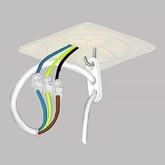
First of all make sure that you have 3 cables of 1 meter each to connect the DIN, 5V and GND from the led strip to the arduino. On each side of the cable you will have to attach a crownstone similar to the image above. The screw is used to make a connection between the cables and to tighten it into place so that you can connect 2 separate cables into 1 long cable. Make sure to strip the cable so that it is the metallic part that connects in the crownstone.
You can strip tiny cables with a scissor on 1 side and your thumb on the other and then you twist the cable so that it cuts it evenly. With thicker cables you can cut it around the edges very precisely.
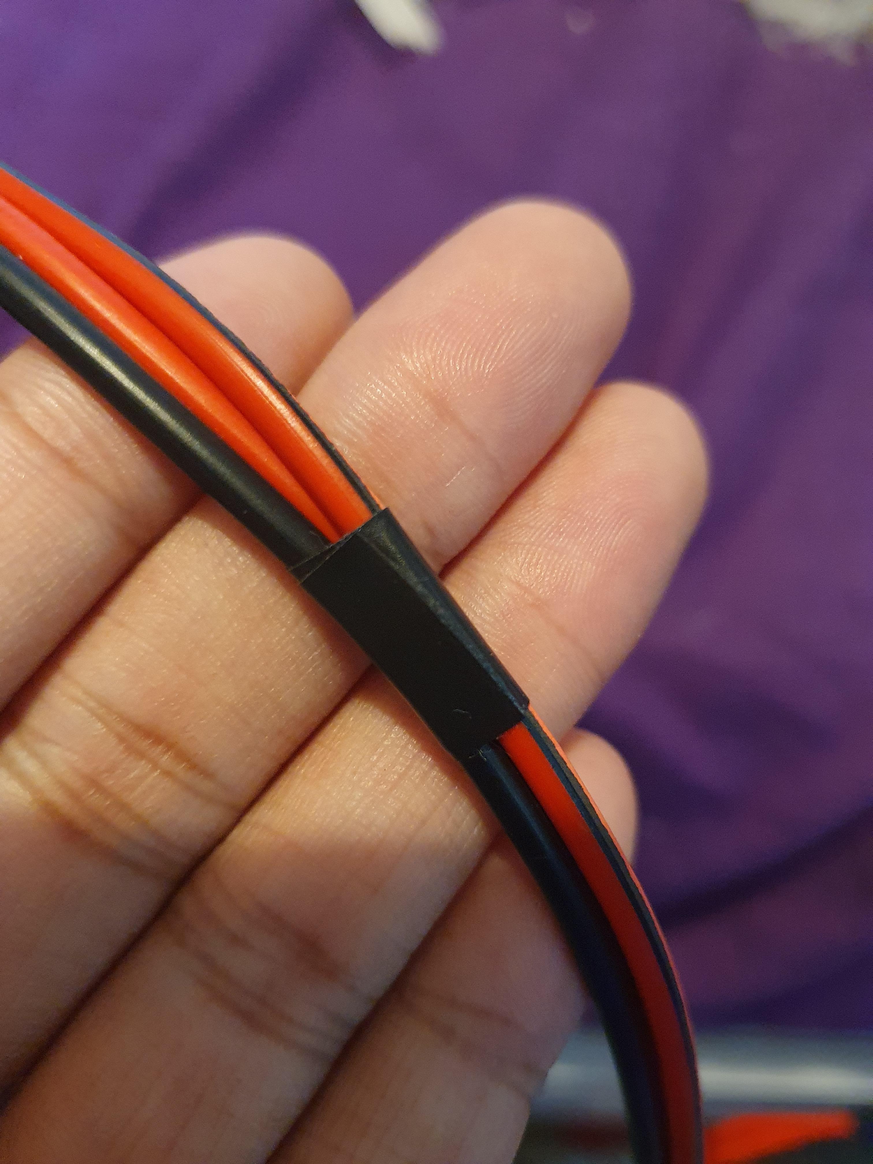
Once that is done you can use the isolation tape around the cables to bundle them at places and also to give them a cleaner look if you want. I also taped around my crownstones to make sure it stays in place.
So by now you should have 3x 1 meter cable going from your ledstrip to your Arduino basically. I suggest bundling the cable together at every 10cm so that it gets more sturdy and sticks to each other. Especially when we are going to use the shoulder bag. You can also use special sleeves for it, but I like to keep things simple so I just use the tape.
You can use the same technique with the jumper cables to bundle them and to even tape them in place with the second part.
But first make sure that your animations are working with this setup.
Step 6: Casing
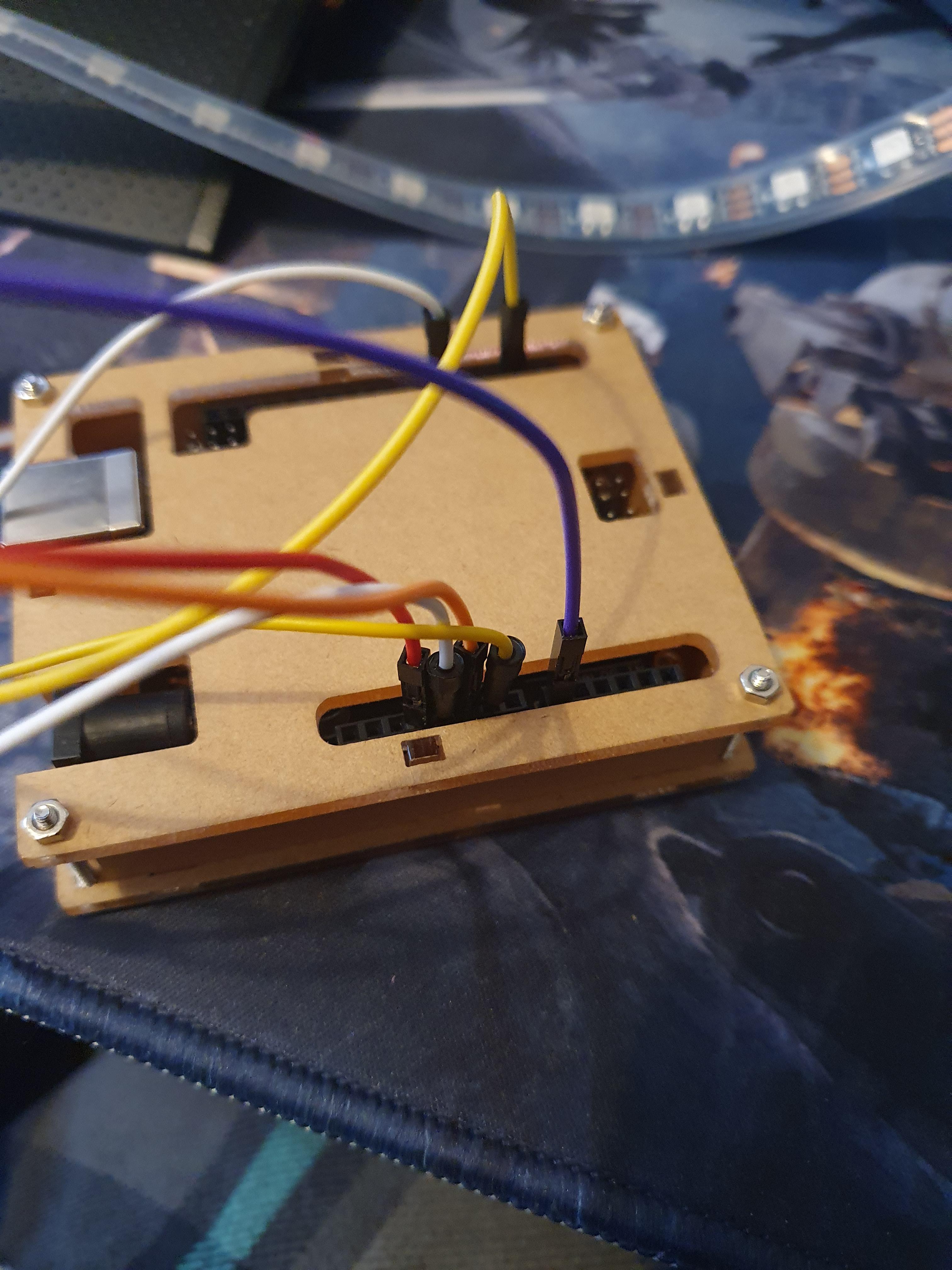
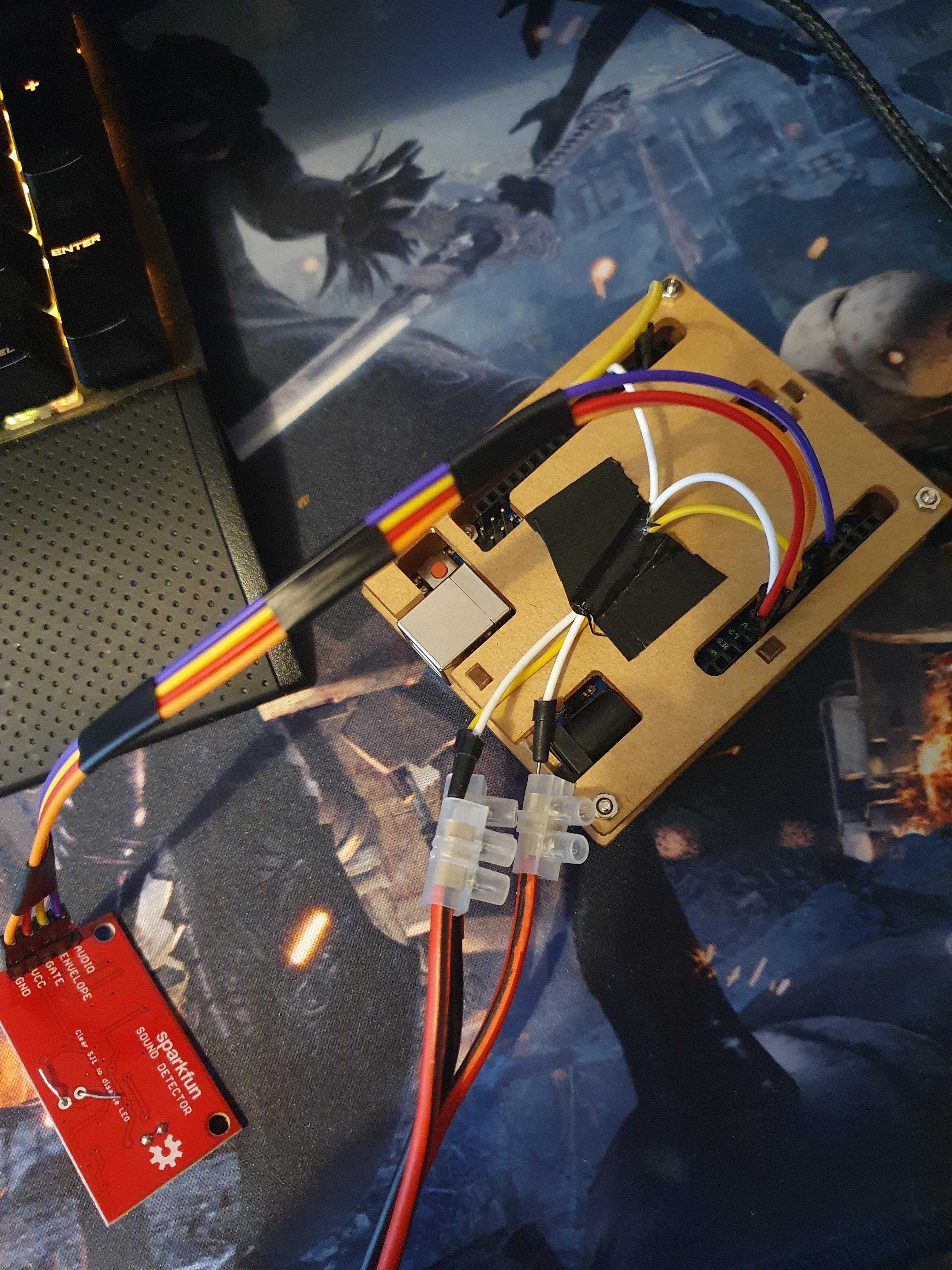
Now it's time to grab your casing and to install the Arduino in the case. Each case is different so make sure to check the manual for it if there is any. Usually it is easy to tell which side belongs where based on the holes.
On the casing you can tape your cables as I did for a quick and dirty test or you can use other more clean alternatives in order to keep things in place nice and sturdy. We will tape the case to the shoulder bag from the back side, but you can also stitch it on there if you attach a piece of cloth for example and sew it in place.
There is plenty of methods, but basically with the casing you will also be thinking about how you are going to implement it in your shoulder bag so that it will be easy to carry around.
By now it might also be interesting to connect your Arduino to the power bank instead of your computer. Everything should work just as before. If the leds are suddenly not that bright then you most likely have a power bank connection that is not 3A with 5V. It is also wise to make sure that the power bank is fully charged.
Once the Arduino is in the bag with the power bank our goal will be basically for it to be powered independently while doing the animations.
Step 7: the Bag
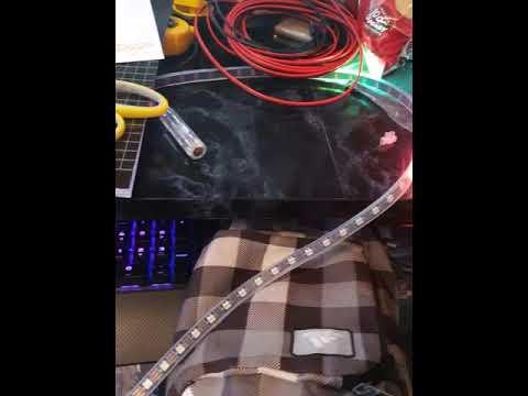
Now we can finally get crafty and work our way to the final design since everything is (hopefully) working properly!
Depending on the type of bag you have, whether it is a new one or an old one you will need to be creative. You will need a compartment for the power bank. You will need a place for the Arduino with the casing somewhere to put the module. Finally you will need to do some cable management to have the wires in reasonable places while keeping in mind that the scarf might be moved a lot so you want to leave some room to breath for the wires or so to say.
Since we want to be able to take the power bank out and move it in conveniently in order to for example replace it or charge it without the bag. Most bags inside have a compartment near the back side. The power bank can be placed in there as it will be held in place and it can be easily swapped out. On the material covering that compartment and separating that space from the inner space is where you can place the Arduino. Depending on the bag you can also place it on a different "wall" inside the bag.
To do this simply stick some double sided duck tape to the backside of the casing of your Arduino. You can then simply tape it inside the bag so that it can be easily removed in the future in case it is needed or if you need to wash the bag. Make sure that it sturdy and that it can deal with a bit of shaking. You wouldn't want your jumping to cause it to get loose now would you?
In case that you attached some clothing to the casing of the Arduino you can also sew it to the bag if you want. You can also maybe even use Velcro so that it is detachable.
So now that your power bank and Arduino have their place inside the bag the audio module also needs a place. For this we need to make a little hole in the bag through which the microphone can fit. This is in order to make sure that it can detect audio without it getting filtered due to the material from the bag. You can attach the module either through tape, maybe a small pocket or any other way that you see fit!
It is important that the internal wire structure is solid. So make sure to bundle cables and that they can be moved, but not at the connection places. The isolation tape can help a lot with this step.
Once your wires are set up and your components are at their places then it is once again time to test!
Connect your Arduino to the power bank and it should automatically start with the animations. You can tap on the mic to test if it is responding properly. If this is not the case then make sure that your wires are connected properly in the right pins. Jumper cables are weak so double check that they are not broken near the pins.
Once everything is working it is time to think about how you want to have the cable that goes from the Arduino to the led strip.
This cable is roughly 1 meter in length so you might choose to attach it partly to the band of your shoulder bag until it reaches the height of your neck. You can also choose to have it just bundled and not attached, which is what I did. Some bags have zip locks other use different type of locks. It is important that the long cable can exit the bag so you might need to make a second hole through which you can allow the cable to go outside. This can be for example near the band so that it doesn't look too out of place.
So now you finally got a bag that hides the components and protects it from splashes and bumps. Out of it you got a cable with a led strip. Plugging the Arduino into the power bank should turn it on and plugging it out should turn it off. So you are almost done with the party set up!
Step 8: the RGB Scarf
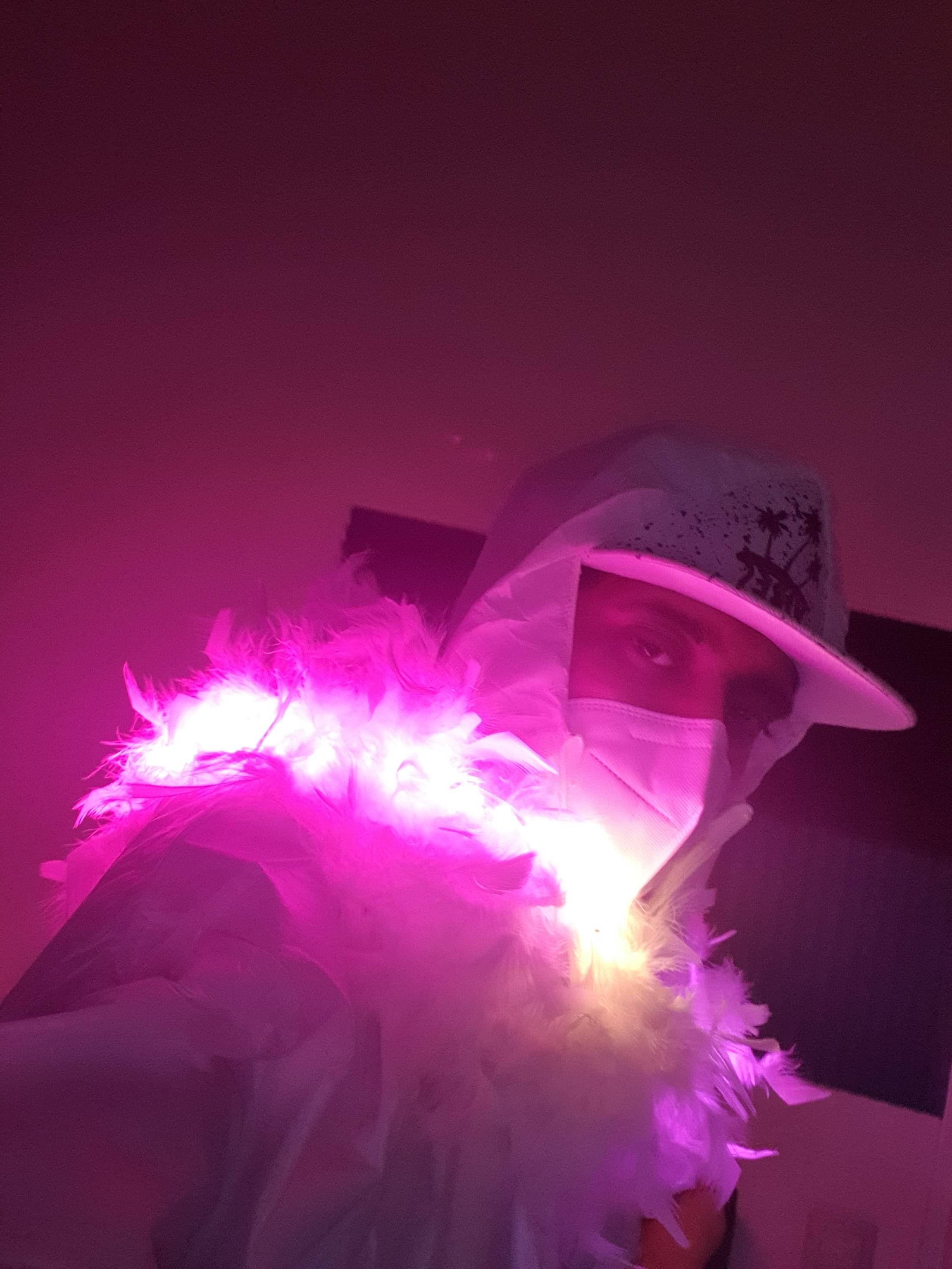
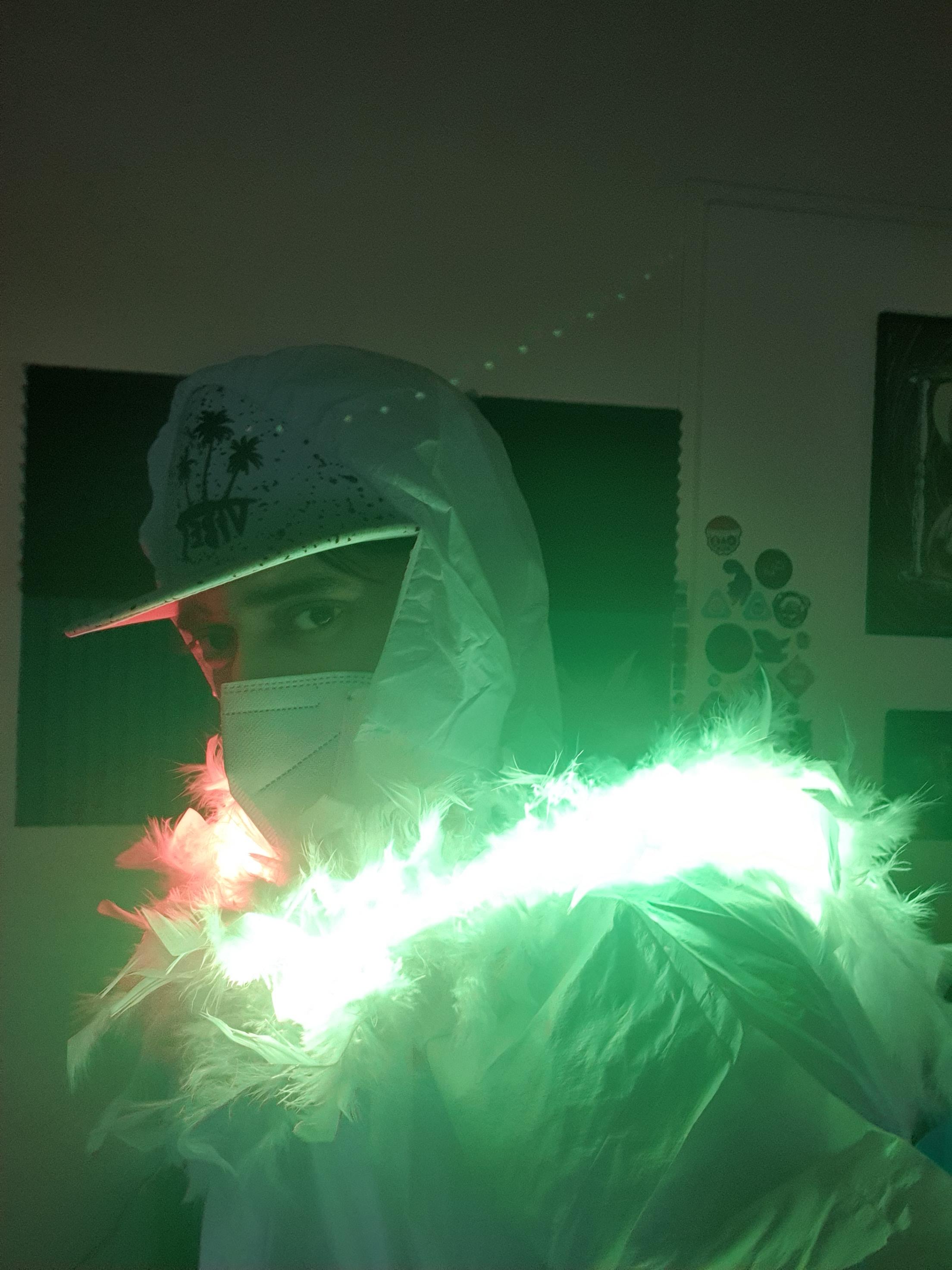
Get those gloves on and get yourself a well ventilated room with a surface that can get dirty. You are about to super glue the feathered scarf to the backside of the led strip.
Super glue can be dangerous if it touches the skin. It sticks very rapidly. If it somehow gets on your skin make sure to immediately wash your skin with soap and water. If it gets in your eyes keep washing it with water and get professional help from for example medics. The fumes from the glue isn't the healthiest either. I would suggest to wear a face mask and to be in a room with the windows for example open.
Now that the formalities and warnings are out of the way it is time to proceed. Put some glue on the backside of your led strip and gently attach the feathered scarf to it. Repeat this process until you have covered the entire meter of led strip. You probably have more scarf than leds, but that is completely fine and normal. It has a nice touch to have some parts without the light effects. You can if you want attach it partly to the cable as well.
I would suggest to have the led side of the strip not glued as this allows the lights to shine more bright than when it is covered. This is also why we choose a white scarf as white doesn't affect the color that comes from the leds.
Final Words
)
And there you go! Your own audio responsive RGB feathered scarf!
This is my first real Arduino project so a lot of things could most likely have been done better, but this should give you the right amount of information in order to at least achieve the same results as me or better.
A lot of things are quite modular and can be easily replaced with a different component. Depending on your budget you can also go for something more fancy or maybe a bit cheaper. Either way this project can be done on low budget but also on a very high budget. Results will of course vary as well.
Coding wise there is a lot of room for freedom. The combinations should serve as solid example about what you can achieve and what the possibilities are.
The final video on here is a full sample of how it reacts to audio.
I hope you will have some fun with this project and that this (my very first) instructable was clear!