Audio Latency Meter
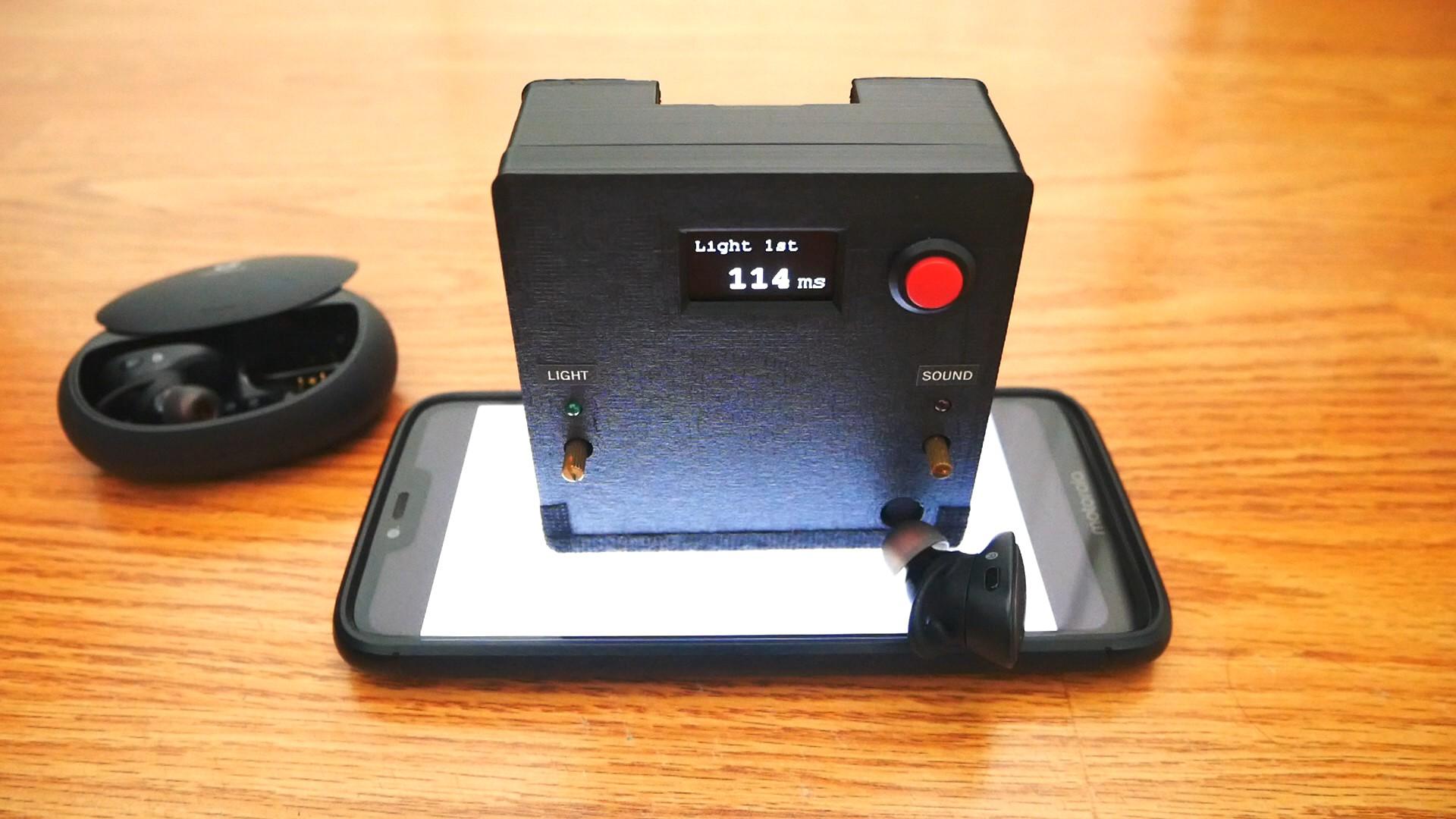
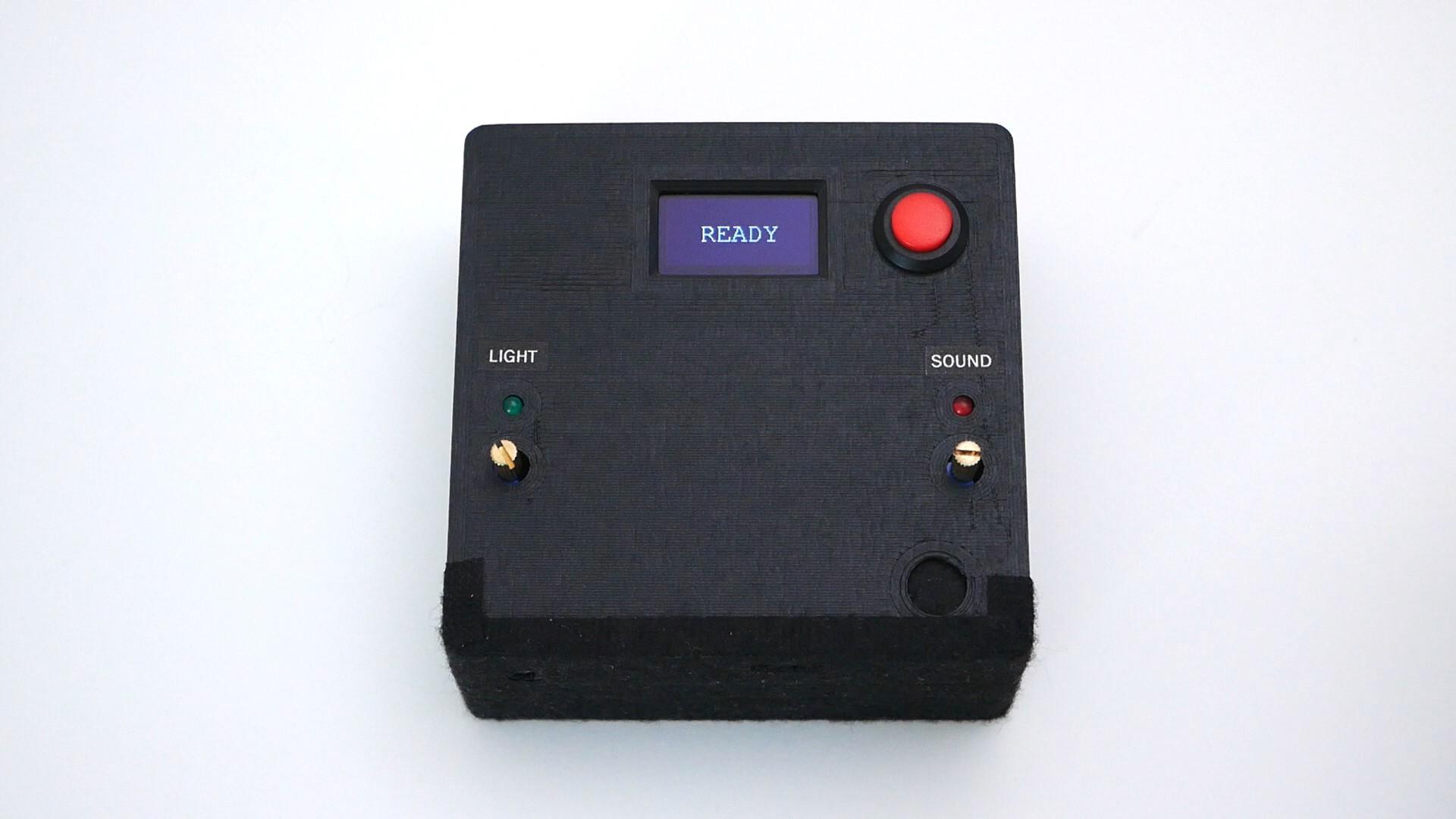
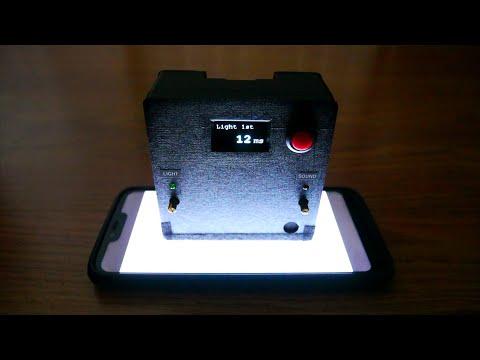
This device measures the latency between the display and the speaker from a phone, computer, TV, etc. The idea is to play a video that shows white frames together with a sound in the device you are testing, and this meter will receive both signals with a light and sound sensors to show the latency in milliseconds.
Why? Bluetooth sound devices (headphones, earbuds, portable speakers, etc.) usually have considerable amount of delay and I wanted a way to compare them in an objectively way.
PCB sponsored by PCBWay - Full feature custom PCB prototype service: https://www.pcbway.com/
Supplies
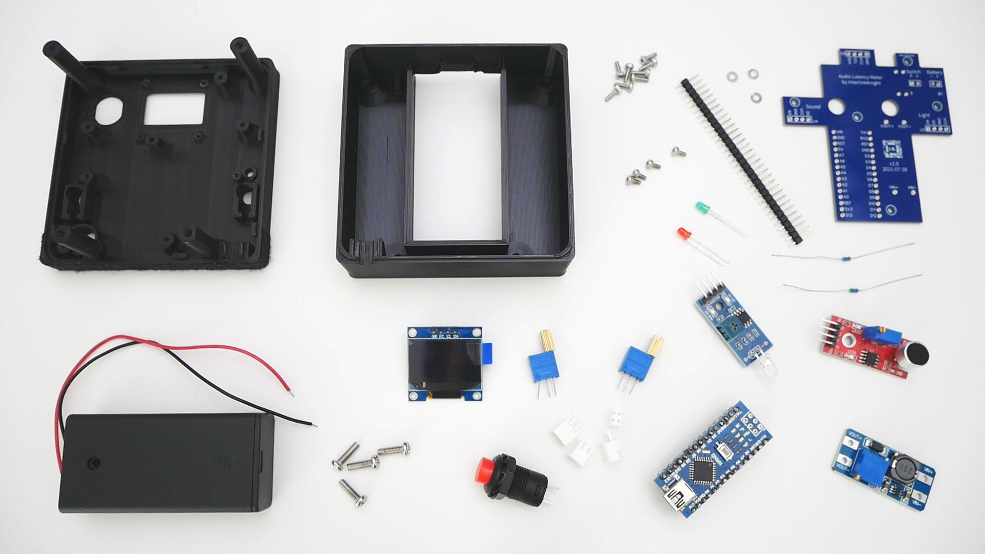
Parts:
- Arduino nano: https://amzn.to/3iru0op
- OLED 0.96" I2C: https://amzn.to/2UNDCLO
- 2 AA battery holder: https://amzn.to/3irHXBU
- M3x10mm Phillips screws: https://amzn.to/3e44FMp
- M2x4mm and M2x6mm HEX screws: https://amzn.to/3fdb0Ff
- M2 Washers: https://amzn.to/3fvwehO
- Resistors 5.1K: https://amzn.to/3TLQD7Q
- Button: https://amzn.to/3gqDu0i
- 2.54mm JST-XH Connector 2Pin: https://amzn.to/3A7yohs
- 10K Ohm Multi-turn potentiometer 3296 with handle: https://www.ebay.com/itm/381427296466
- 100K Ohm Multi-turn potentiometer 3296 with handle: https://www.ebay.com/itm/163800069566
- Light detection photodiode module: https://amzn.to/3uyMTJU
- Sound detection microphone module: https://amzn.to/3a0xXeo
- MT3608 DC-DC boost converter: https://amzn.to/3D0tyEs
- 3mm LED: https://amzn.to/3VLUq7U
- 2.54mm male pin headers: https://amzn.to/2Y8WDia
- Custom PCB: order from PCBWay.com using these gerber files.
- 3D printed case: https://www.thingiverse.com/thing:4979910
Recommended Tools:
- Breadboard (good quality): https://amzn.to/2QsyY3C
- SpeedEII Electric Screwdriver: https://amzn.to/3VzTkcD
- Multimeter (Fluke 17B+): https://amzn.to/2L3PNQk
- Rigol DS1054Z Digital Oscilloscope: https://amzn.to/2C5ZwD7
Note: As an Amazon Associate I earn from qualifying purchases.
Test
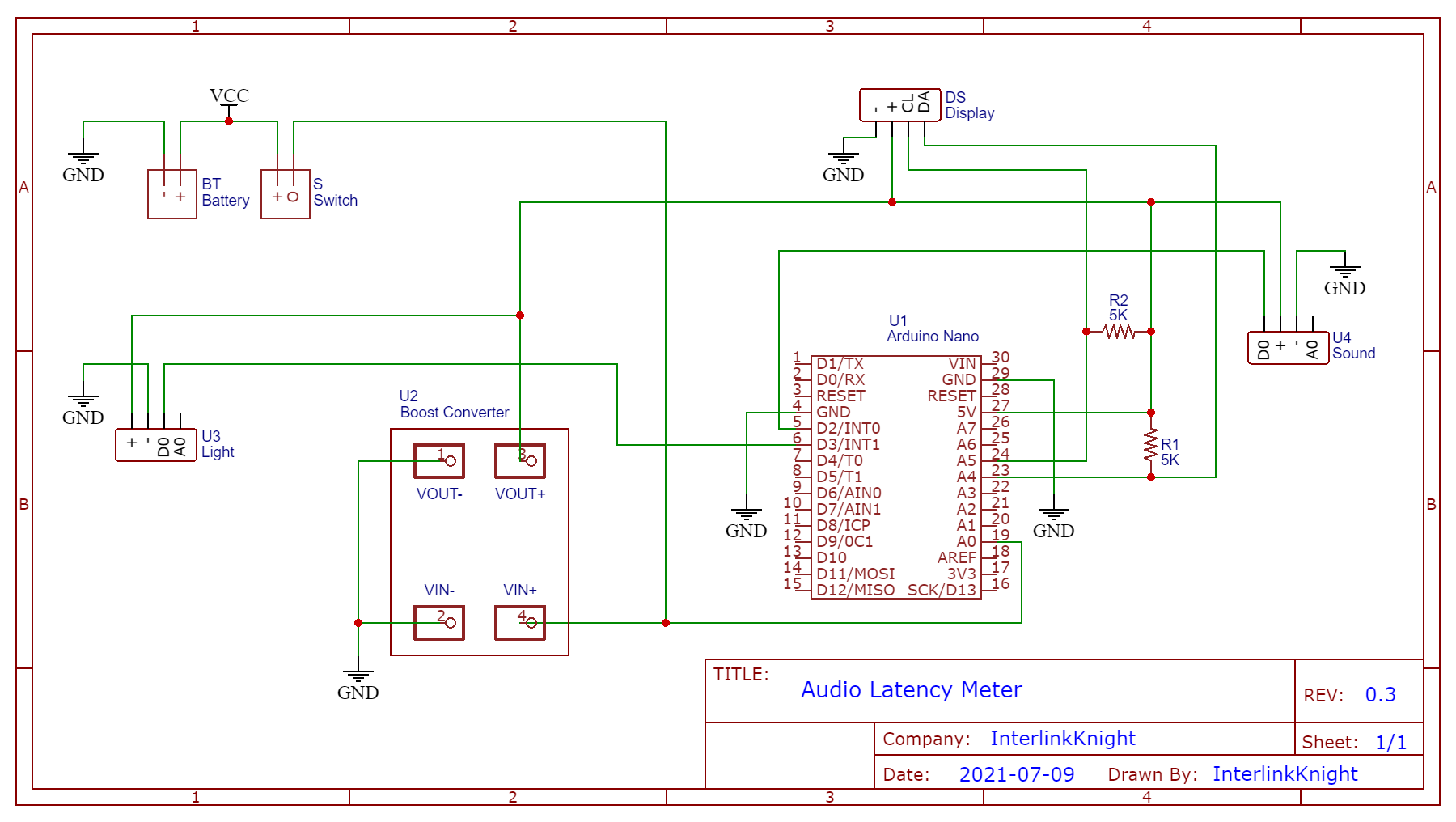.png)
- Connect everything in a breadboard as shown in the diagram.
- Download the Arduino Sketch and upload to your arduino nano to test everything.
Modify Sensors
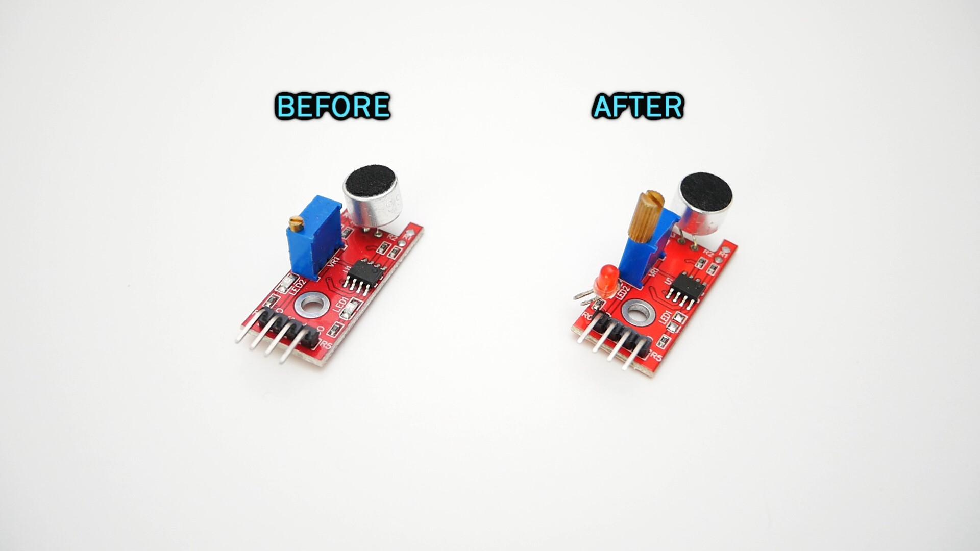
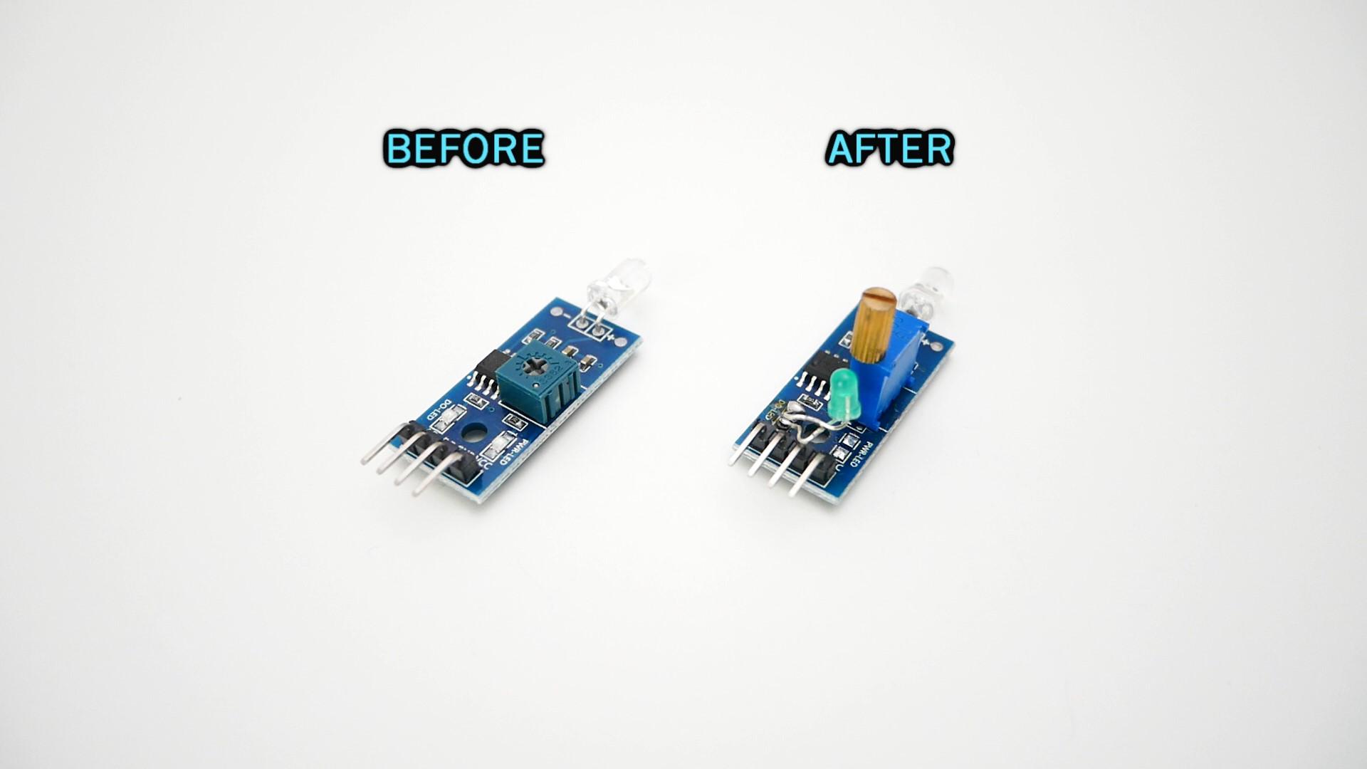
- Replace the potentiometers with the ones that have knobs/handles. The sound sensor uses 100K and the light sensor uses 10K.
- Replace the LED and leave the long pin so it can reach the surface of the case.
- (Update) Replace the light sensor with a photoresistor: https://amzn.to/4ctckm0 This will make it more sensitive, which was a problem with the original sensor.
3D Print the Case
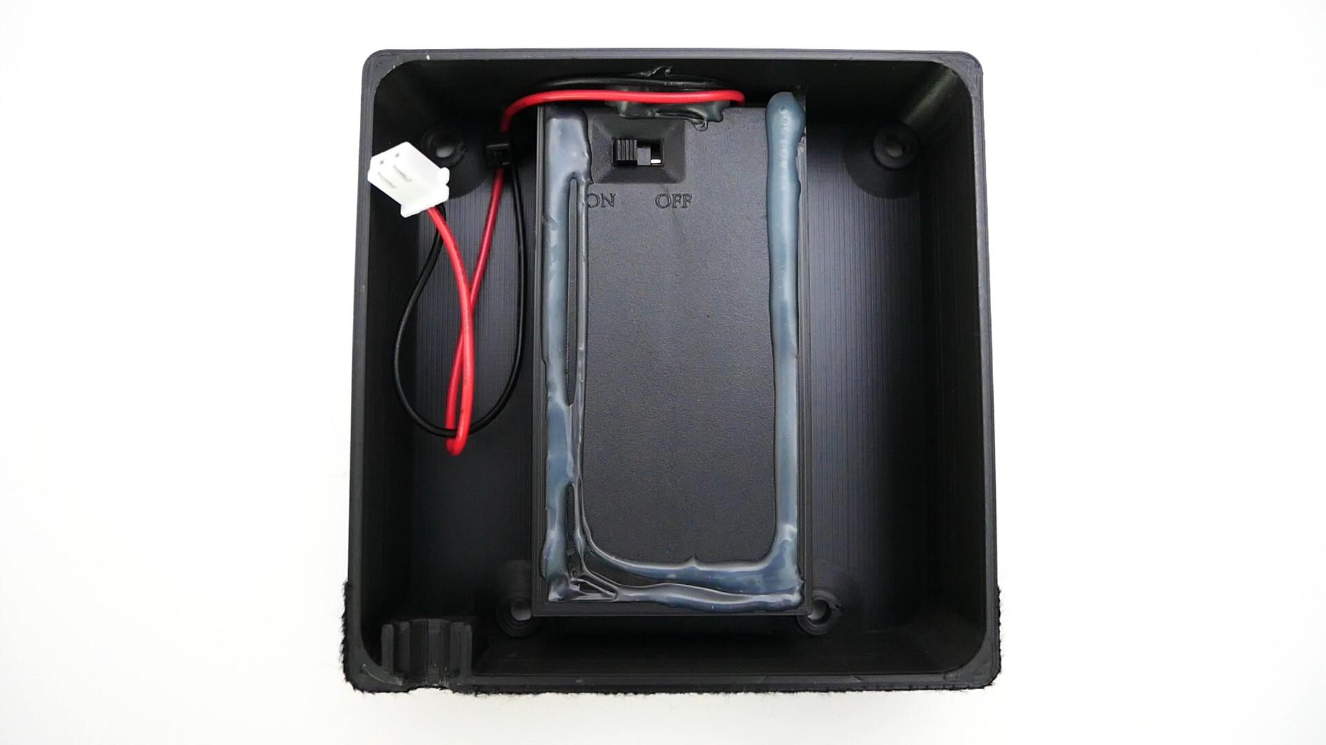
- Get the files in here: https://www.thingiverse.com/thing:4979910
- Glue the battery holder to the back case cover.
- Add the connector for the battery holder and the button. The back cover has a small place where you can put a zip tie to hold the cable of the battery holder.
- Place the power button in the front case cover.
The PCB
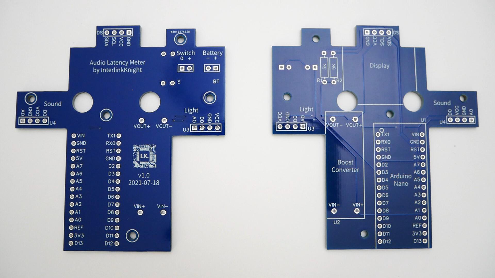
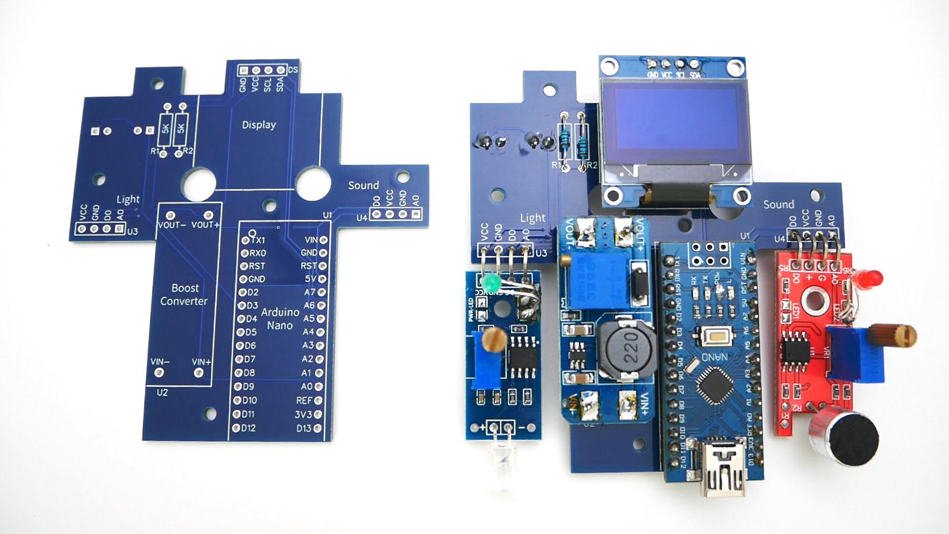
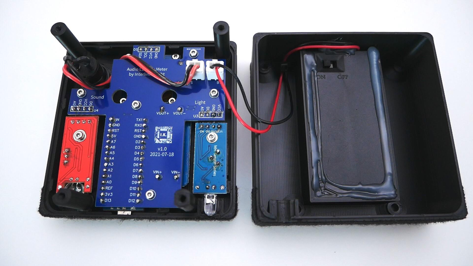
- Order my custom PCB from PCBWay.com using this gerber files.
- Solder the Arduino nano, the boost converter, the resistors and the connectors.
- You need to first screw both light sensors and the display to the case, before been able to solder it to the PCB. The display uses M2x4mm screws, and everything else uses M2x6mm HEX screws. You need M2 washers on both sensors, and another one to hold the microphone to the case.
- Screw the PCB and that will give you the natural position for the pins of the sensors and the display to be soldered. You have to bend the pins for the sensors to reach the PCB.
Finishing
- Screw the back case cover using M3x10mm phillips screws.
- Place the sticker/labels.
- Cover the bottom of the device with soft tape so it doesn't scratch the surface of the display we are testing.