Atari Punk Synth, Neko Edition
by Arnov Sharma in Circuits > Audio
3033 Views, 20 Favorites, 0 Comments
Atari Punk Synth, Neko Edition
.gif)
.gif)

Hey Guys how you doing!
This is the NEKO PUNK Synth which is a cat-themed Atari Punk Console based around two-timer ICs.
This circuit utilizes an astable multivibrator setup which triggers a monostable setup.
By combining these two setups, we get a Stepped Tone Generator or an atari punk synth.
APC or the Atari Punk Console was first made by Forrest Mims in 1980 and it was called sound synth back then. Also, it is not made by Atari at all, the only reason for calling this sound synth APC is the resemblance of sound produced by synth is somewhat similar to the early atari games, beeps hums, and other stuff.
Anyways, this version of mine follows the same old two-timer ic circuit, only twist here is the cat-themed box and the addition of a sound AMP between speaker and APC.
Supplies
these are the materials used in this project-
- 555 Timer IC (both THT and SMD)
- 10uf capacitor
- 0.1uf capacitors (SMD and THT Both)
- 1K Resistor
- FR4 PCB Copper Clad Board
- 10K POT
- 500K POT
- PAM8406 Module
- Breadboard
- Power Source (in my case, a Lipo Cell with a Boost module 5V)
- 4 Ohms Speaker
- 3D Printed Parts
PROLOGUE
.gif)


So the idea here was to make an APC, a completely DIY APC which will have an inbuilt power source and it should be portable so anyone can carry it from one plate to another.
Previously, I've made a similar APC with an Atmega328PU microcontroller connected with a PAM8406 Module. It uses Mozzie Library to modulate sound with 5 potentiometers.
https://www.instructables.com/Arduino-Based-Synth-...
That setup worked flawlessly without any issue, but the problem was its cost. I wanted to make a similar synth without using any Microcontroller in this project to overcomplicate things, so instead of relying on a library, I used the good old-timer IC Tone generator setup which utilizes two 555 timer ic connected in an astable multivibrator and monostable setup.
this significantly reduces the cost of the overall project and anyone can remake this without utilizing any code.
Getting Materials From ALLCHIPS
.gif)
As for the Source from where I get most of these components, I got the Timer ICs, Resistors, and capacitors from ALLCHIPS.
ALLCHIPS is a well-known Platform For Electronic Components Supply, they have everything that you need for any type of project.
They are an all-in-one procurement department of hardware manufacturers as all components I used in this project were provided by ALLCHIPS which was a cool and helpful thing!
Also, they have this BOM IN ONE BOX thing which is such a helpful thing, we provide them a BOM List and they procure all the components and deliver them "IN ONE BOX" which is an efficient way of purchasing components for any project!
Check out ALLCHIPS for more info.
GETTING STARTED


For getting started, I first prepared a breadboard version to check if the circuit is working properly or not.
after making sure that the schematic was working, I prepared a PCB Version.
Breadboard Edition
.gif)


To prepare the breadboard edition first, I used the Tone generator Circuit (which is attached above) that consists of two separate Timer ICs connected in both an astable multivibrator and monostable multivibrator. their output goes into a PAM8406 Module and the whole setup is powered by a lithium battery boost module.
Sound can be modulated via Pots connected with Timer IC 1,2 and between the Timer IC output and speaker input.
PCB Edition


For the PCB Edition, I first prepared the schematic of the board by following the same breadboard layout but the only difference here would be that I have used SMD Version of 555 timer ic which is in the SOIC8 Package.
Also, for this version, I will be using a completely DIY PCB instead of a proper one because this project is still in its early phase and I will add a bunch of stuff in it later on so for now, this design has three pots.
STEPS
.gif)
.gif)
.gif)
.gif)
- After finalizing the schematic and making the PCB, I printed its bottom layer on a glossy sheet in the real size.
- Next would be the tone transfer process which involves transferring the ink from glossy paper to a copper FR4 board by using a heat source that is this cloth iron.
- I cut down a rectangular piece from the FR4 Copper clad board and used sandpaper on its surface to make it shinier.
- Now we take the Glossy Paper cutout and place it on this Copper board and use a cloth iron to press down the glossy paper. by doing this, cloth iron will heat the PCB and the ink from glossy paper gets transferred onto the surface of the FR4 board.
- after doing this, Glossy paper will stick to the FR4 board and we need to separate them both but not by pulling the Glossy sheet, if we do that, PCB traces might also come off which would be not good.
- The solution here is water, we dip this board into the water and just rub the paper so it gets dissolved and comes off the surface without affecting the ink.
- the result will be a copper board with PCB Traces, but here's a problem, a few traces didn't stick properly to the copper board and now we have a few empty lines and pads.
- Not a problem as we can draw those traces with a CD Marker, just make sure to use two or three coats of the marker to make the ink deposit more on the copper surface. The goal here is to cover a thick ink on the top surface of copper, we will wash away the exposed copper with an etching solution and the remaining track will be under the ink we used.
MORE STEPS
.gif)
.gif)
.gif)
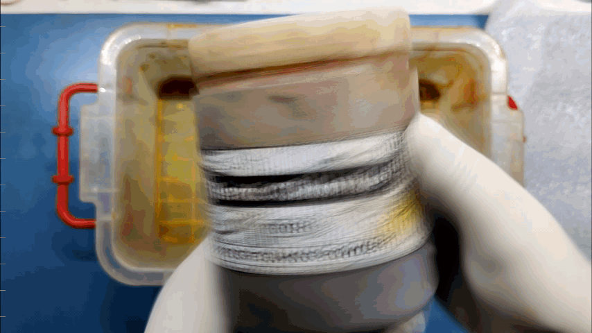
- Now we prepare the etching solution which would be a mixture of ferric chloride and water.
- also, before working with ferric chloride, make sure to wear a mask and rubber gloves to protect yourself from its foul odor and color.
- we prepare the solution by adding ferric chloride into a small bucket and then adding water to it.
- then we place the circuit inside it and start the move the bucket in this way, by doing this the copper will slowly wash away.
- after a few mins, the result will be a PCB that doesn't have any exposed copper area left, we first clean the board with water and then use sandpaper to scrape away the ink which is on the board, under this ink, copper is left which didn't wash away by the ferric chloride solution.
PCB ASSEMBLY
.gif)

Now we start the PCB Assembly process, first I gather all the parts needed for this built and started the soldering process.
this board is just a one-sided board which means I had to add jumpers in a few traces and for that, I used silver copper wire.
(For the Location of each component, you can see the attached schematic)
Connections
.gif)


after adding traces, we now have to add wires on the potentiometer and then connect this circuit with all three pots, then we add the PAM8406 module with the circuit and then the Li-ion boost module setup by following the attached block diagram.
3D DESIGN

.gif)
.gif)
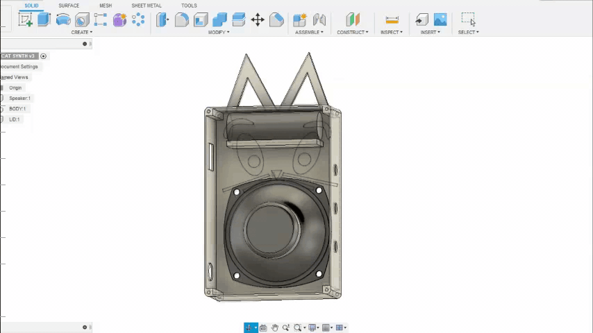
As for the Body of the Synth, we generally use a Box like enclosure right which will house the speaker and electronics.
Well, I had this idea of making a cat face on the front side so I added a bunch of cat face stuff on it like a nose, a few whiskers, eyebrows, and cat ears.
I modeled the body in fusion360 and then 3D Printed each part on my ender 3. I prepared the main body with GREY PLA and Lid, pupil, eyebrows, whiskers, and nose from BLACK PLA and the eyes from white PLA.
The print setting was normal as well, I used a 0.5mm nozzle with 0.2mm layer height with an infill of 20% and support for the base body.
Face Parts Assembly
.gif)
.gif)

After printing all the parts, I used super glue to attach all the face parts to the base body.
And yes, it does look like that cat mechano from tom and jerry but that was a coincidence, I didn't model it after mechano but maybe I will prepare a V2 based on that.
FINAL ASSEMBLY
.gif)
.gif)
.gif)
.gif)
.gif)
- Now we start the main assembly by first adding DC Jack and a switch into the base body. DC Jack is for changing the Lithium Boost module.
- Next, we add a speaker onto the Base body with nuts and bolts.
- then we connect the Lithium Boost module with the DC jack and switch
Now, for preventing shorting of the exposed circuit, I added fiber tape to cover the synth circuit completely along with the lithium boost module and Audio AMP Module.
after this we can now place the potentiometers in their assigned place with some hot glue, the pots that I'm using are old and I didn't have their bolt which holds them in place so I used hot glue but you should use the bolt option.
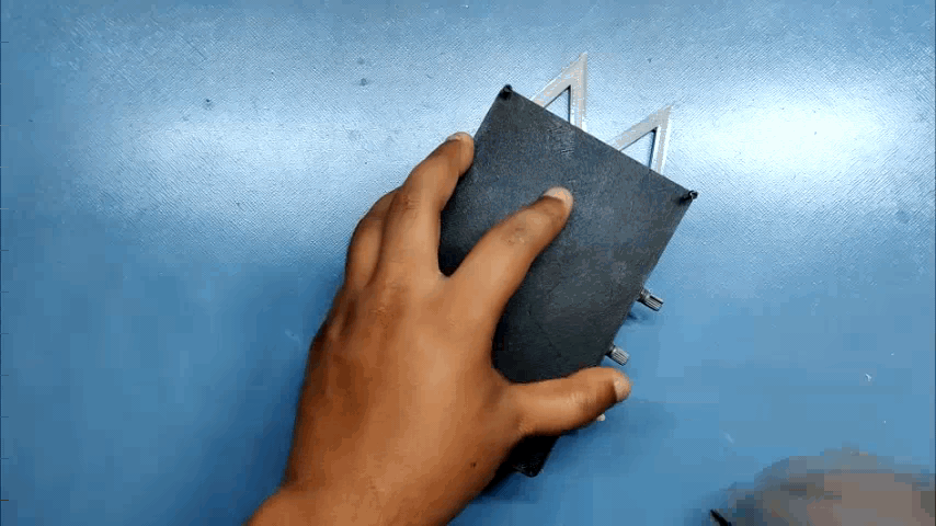
then after this, I place all the stuff inside the body and add a lid on the bottom side with some M2 Screws.
And the setup was completed!
RESULT
.gif)
Now we test this setup, and for that, we only have to turn on the switch and use Pots to modulate sound.
something like this-
And that is it for today guys, be sure to check my previous synth projects If you're interested in synth, and I'll be back with another project soon!
Peace