Atari Punk Console - FabLab NerveCentre
by TonyCanning in Circuits > Audio
1902 Views, 19 Favorites, 0 Comments
Atari Punk Console - FabLab NerveCentre
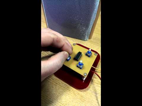
First, I'd like to acknowledge a young man who called into the FabLab here in Derry one evening with an APC made up on a breadboard. Twelve year-old Vincent is interested in learning how to solder to avoid the annoyance of poor connections and gave us a demo of his Atari Punk Console. I had heard of 555 timers before but not of the APC unit so only for Vincent, this wouldn't be here on instructables.
Cheers Vincent!
_______________________________________________________________________________________
There are other instructables for the Atari Punk Console, also known as a "Stepped Tone Generator".
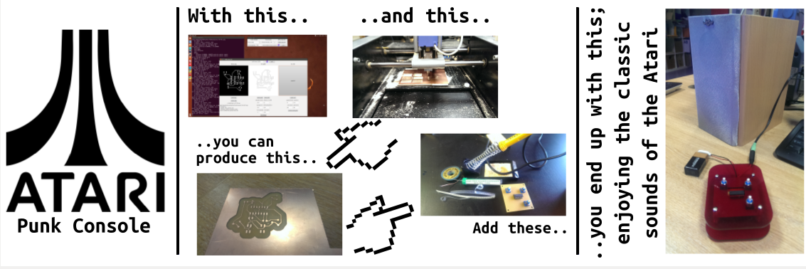
This one is as much about my methods of getting everything prepared and processed as a milled PCB rather than breadboarding it.
Breadboarding has it's uses of course and if I'm honest, would have saved me some pain in what I've done here! However, sometimes you want to move past breadboarding so that smaller components can be used and you could potentially produce a product.
Stuff You'll Need
2 x 500K linear potentiometers
1 x 100K logarithmic potentiometers
1 x 556 timer chip
1 x 14 pin DIL
1 x 1K resistor
2 x 0.01uF capacitors
1 x 10uF capacitor
2 x header pins
1 x 9V battery & snap
2 x header connections
1 x 3.5mm audio out
I've used components suitable for surface mounting. Of course you can use alternatives if you like.
Preparation With Eagle

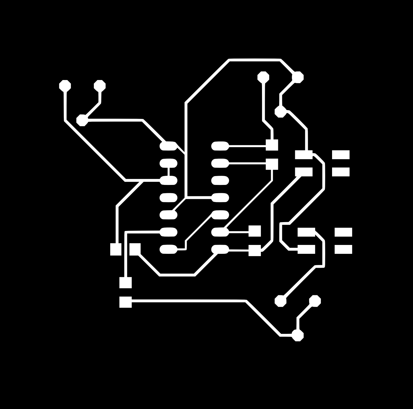
I'm not going to make this a comprehensive instructable on eagle or fab modules, but hopefully some of the information below will be useful:
Downloading eagle: Eagle for Windows, Mac or Linux
The libraries I used are attached (*.lbr files) and should be placed in your eagle libraries folder. For me (on Ubuntu) this folder is located at /home/username/.eagle/lbr/
The eagle schematic and board are both attached.
Also attached are 3 png format images exported from the final eagle board.
Preparation and Use of Fab Modules

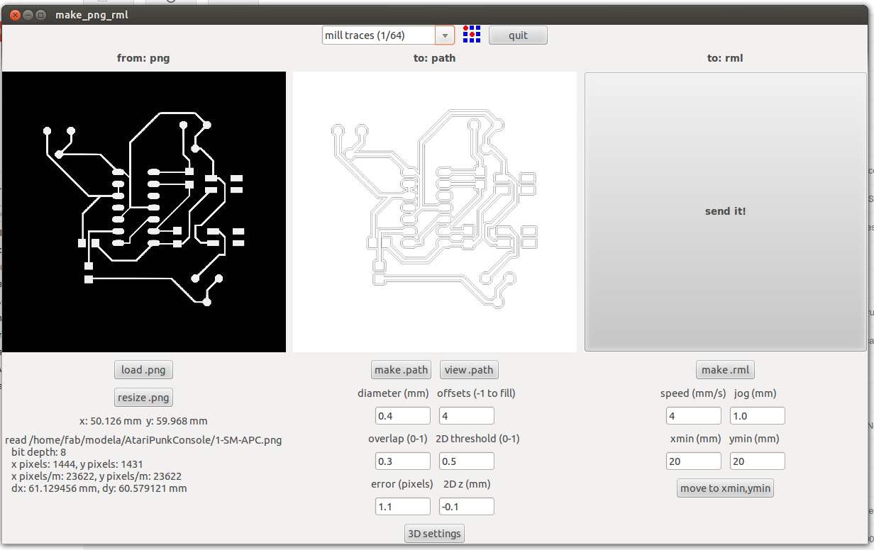
Once again, I can offer advice on fab modules based only on Ubuntu.
Use CTRL, ALT & T to open a terminal. Paste the following and enter your password when prompted:
sudo apt-get install python python-wxgtk2.8 python-dev python-pip gcc g++ libpng12-dev libgif-dev make bash okular libboost-thread-dev libboost-system-dev cmake
Download fab modules from: http://kokompe.cba.mit.edu/fab_src.zip for the most recent version.
*note1: I've experienced problems with this version of fab modules. Now I use the older version which is available as an attachment to this step. See later note2 if you need to go to the older version.
Follow these steps to create your fab modules executable:
mkdir ~/Desktop/fabmodules
mv ~/Downloads/fab_src.zip ~/Desktop/fabmodules/
cd ~/Desktop/fabmodules/
unzip fab_src.zip
make fab
sudo make install
To run fab modules you can now type "fab" into the terminal.
*note2: If the most recent fab modules don't work for you or if you have problems with running them as I have there is a solution. The attached "fab.zip" file is an older version of fab modules. Download this file and copy the contents of the bin directory to the location of your fab modules install. Open the terminal and type:
cd ~/Downloads
unzip fab.zip
sudo cp -r bin/* /usr/local/bin
Using fab modules:
From the appropriate drop downs, select "from format:" image (.png) and "to process:" Roland Modela (.rml). You will note that the "with program:" button changes to make_png_rml. By hitting this button you will be offered a new window in which you need to load your png image.
Before making the path there are several parameters you can change. At the top of the window, select for milling the surface of the board. This changes settings to the default for a 1/64 end mill.
Once you have made any required changes, hit the make .path button. Now you can set the Z height of the mill to the surface of the material and create the file to be sent to the mill by hitting make .rml.
The large "send it!" button will begin processing the board.
For some boards you will only need to mill the surface (in the case of only using surface mount components). However, in this case you will also be using a 1/32 mill in order to drill the holes for the through hole components.
Downloads
Soldering Your Components
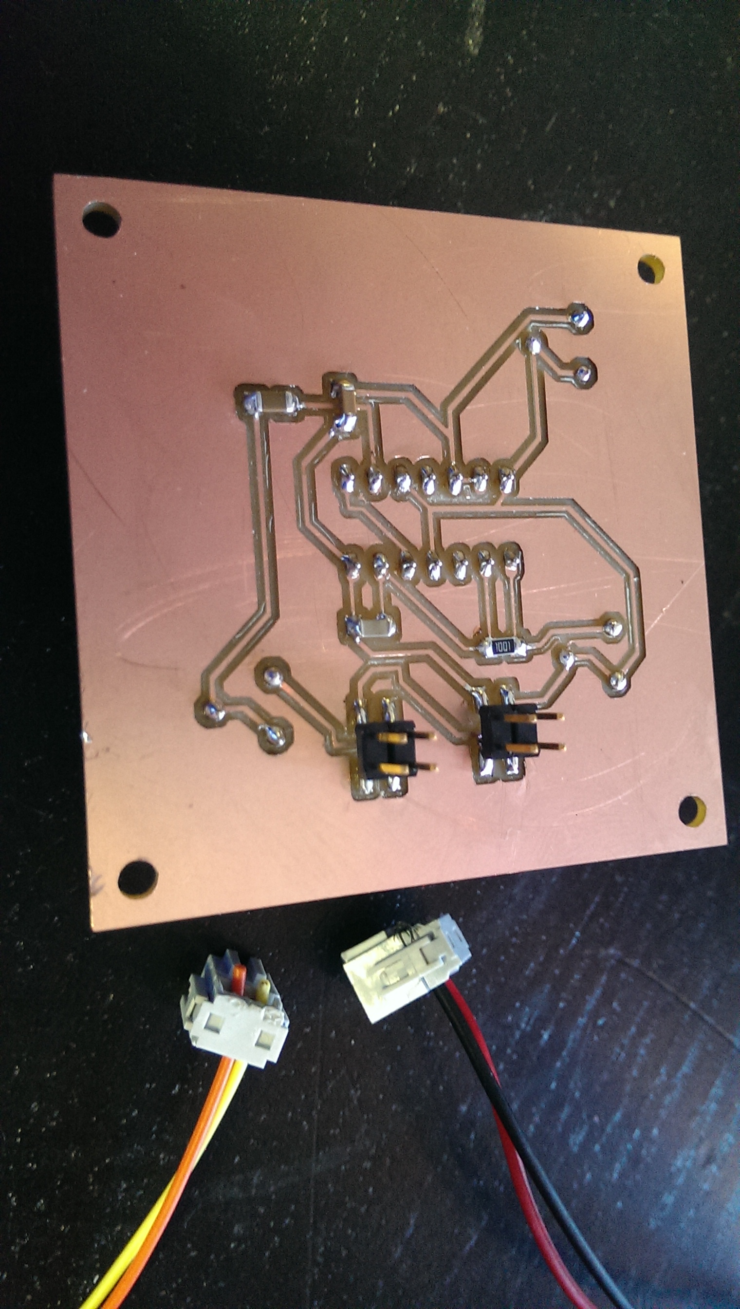
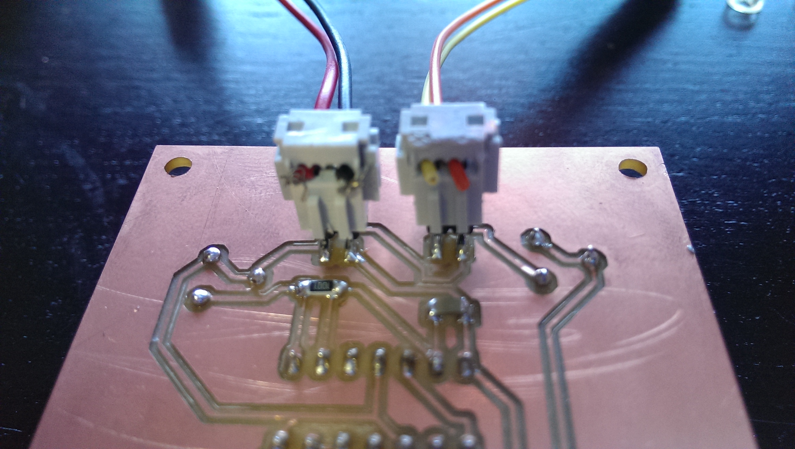
The majority of the soldering is through hole soldering.
Just a few components are surface-mount.
Take care when soldering on the board to avoid applying too much heat as this can cause the traces to lift.
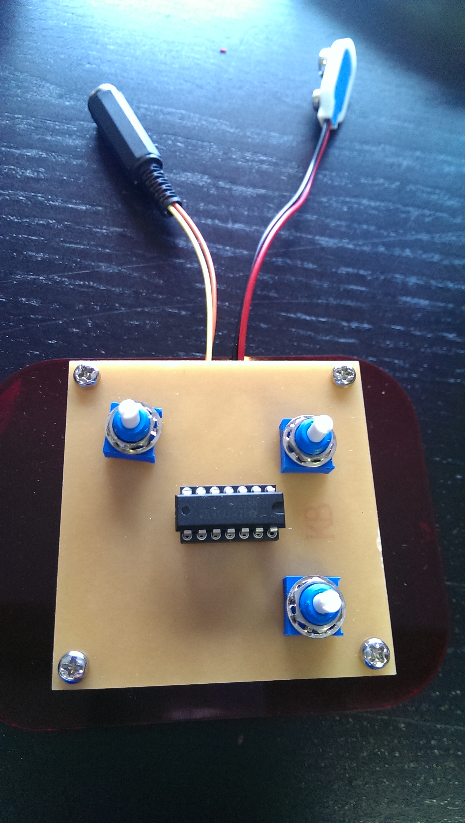
Once all components are soldered you can attach a speaker to the APC and test it.
Not Working?
If your APC is not working there are several steps to take in troubleshooting.
First things first: check that your battery is not empty and that you have connected it correctly to the board.
Next you can check the speaker connections. Also ensure that you have orientated the 556 timer chip correctly.
After checking these, it's time to check your soldering. If you haven't got a lot of soldering experience there are a few mistakes that can be easy to make. You could miss a connection or could cause a short but connecting something that shouldn't be - so check all the connections for both of these issues.
If you think that everything is a-ok after making the above checks then I'd advise breaking out the multimeter.
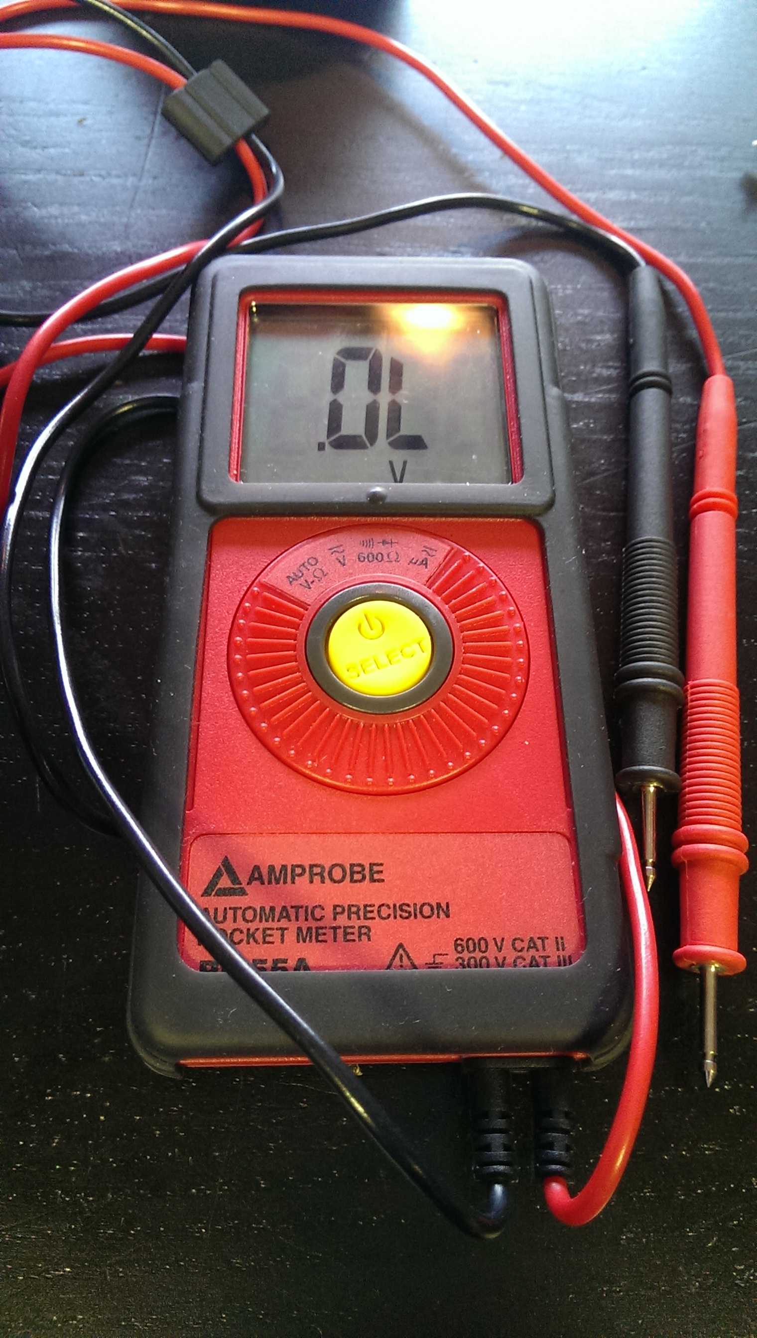
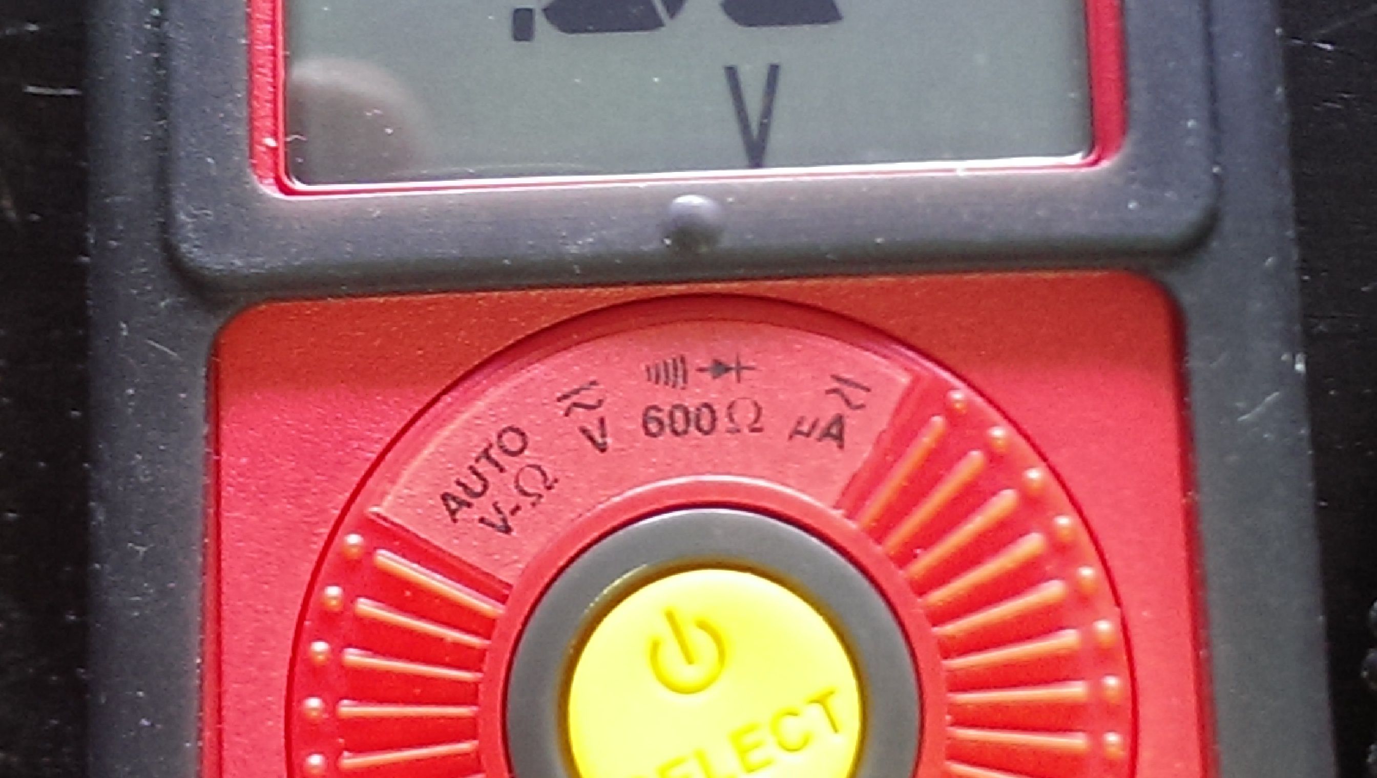
The multimeter will have several settings. We want to check for continuity so we turn to the setting for that (pictured).
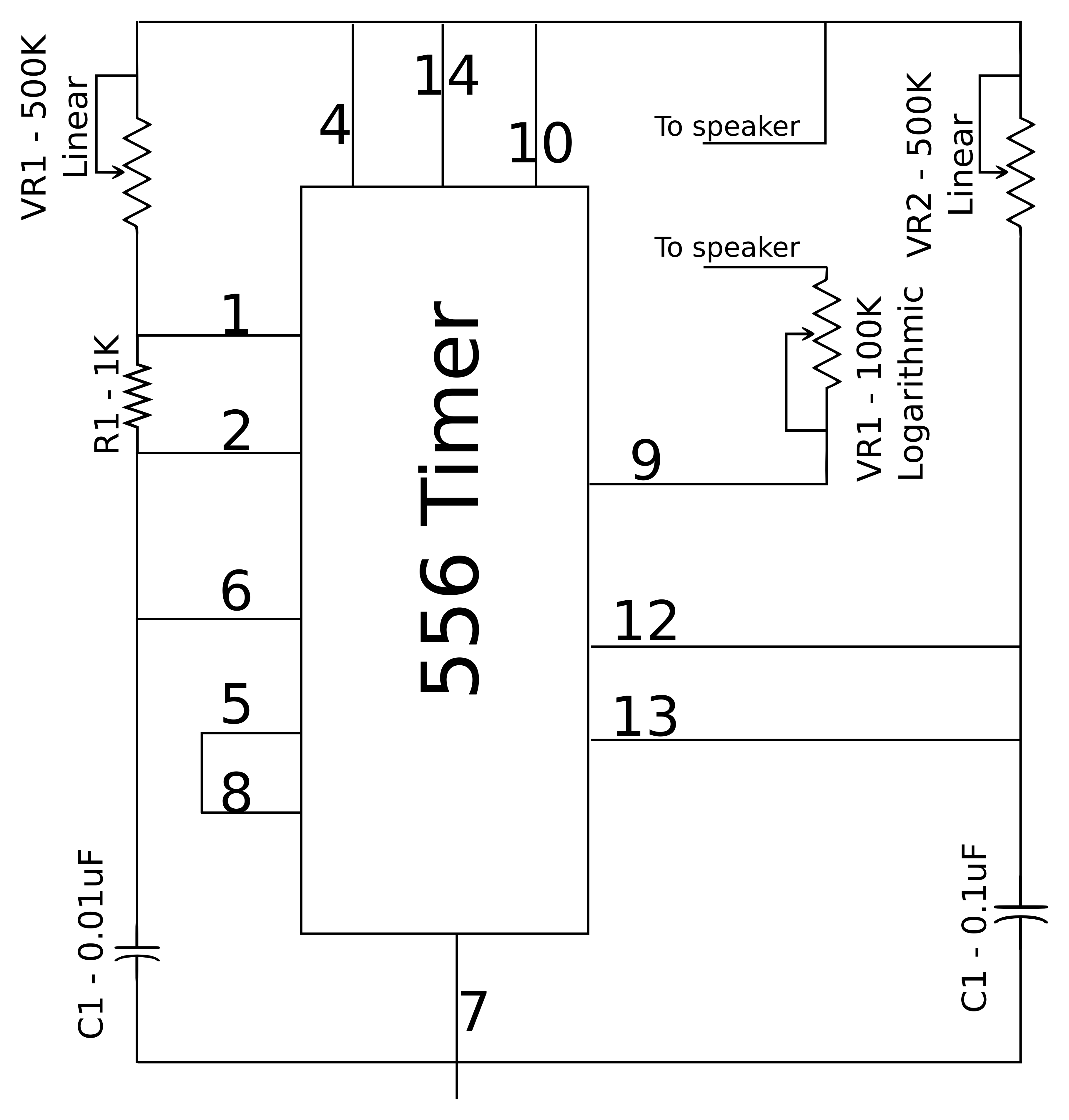
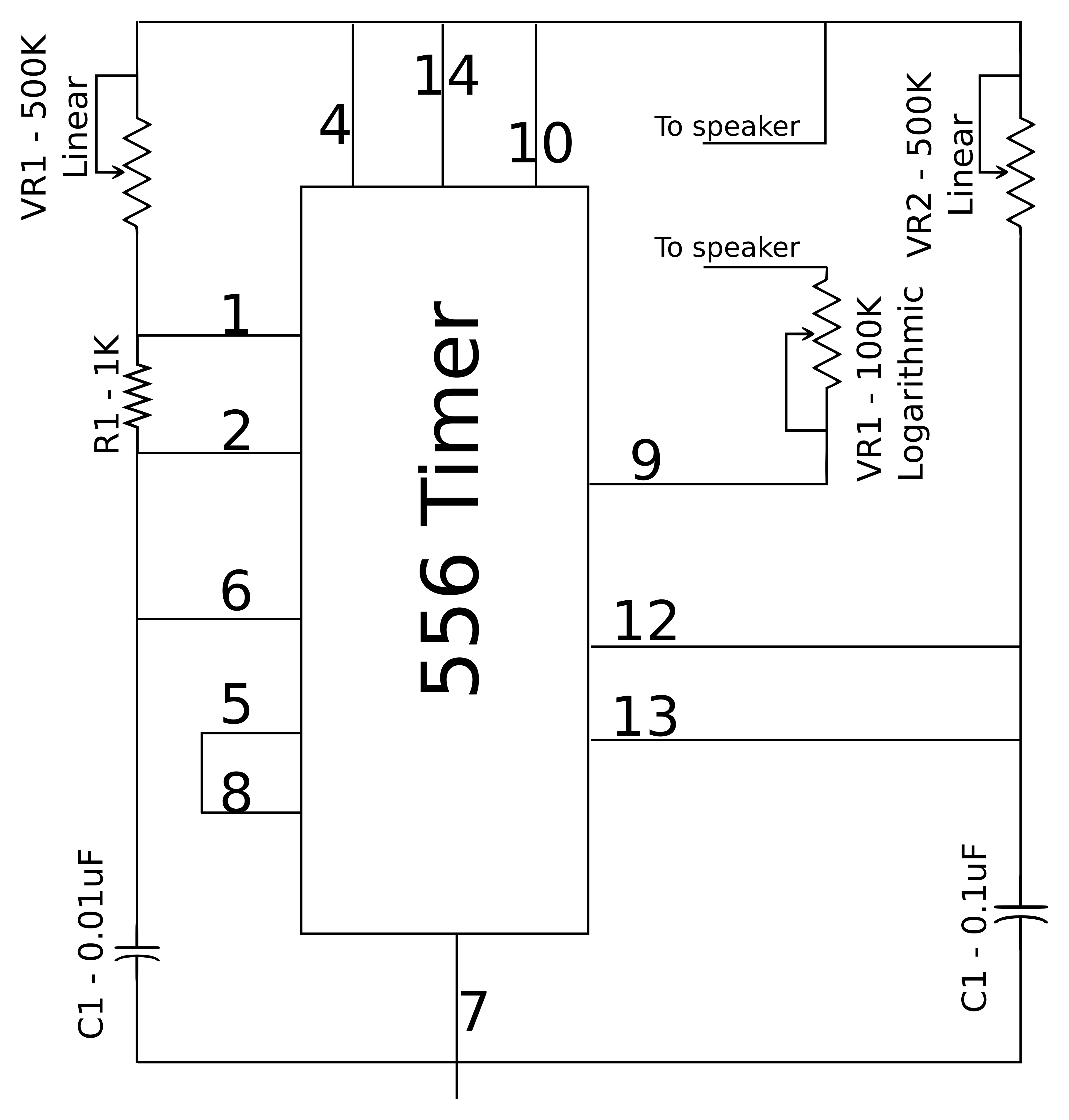
Touch the red probe against the black probe and you should hear a constant tone. Refer now to the schematic and you will see that connections are made between different components. For example, pin number 7 is GND and is connected to the GND side of the battery and to one end of each capacitor. You should get a constant tone by touching the multimeter probes to pin 7 and to each of these components.
If you're not getting the continuity tone from these tests, then contact is not being made and you need to address this with checking your solder connections.
Checking for continuity is also very handy for checking for connections which should NOT be made. For example, no connection should be made between V+ and GND. If there is, you will likely have noticed significant heat build up in the circuit/556 chip and/or the battery itself.
Hopefully, you can get your APC working, if you are having any specific problems please feel free to comment below and I'll do my best to address them!