Assembling "Wise Clock 2" (Arduino-based Alarm Clock With Lots of Extra Features)
by florinc in Circuits > Clocks
13256 Views, 24 Favorites, 0 Comments
Assembling "Wise Clock 2" (Arduino-based Alarm Clock With Lots of Extra Features)
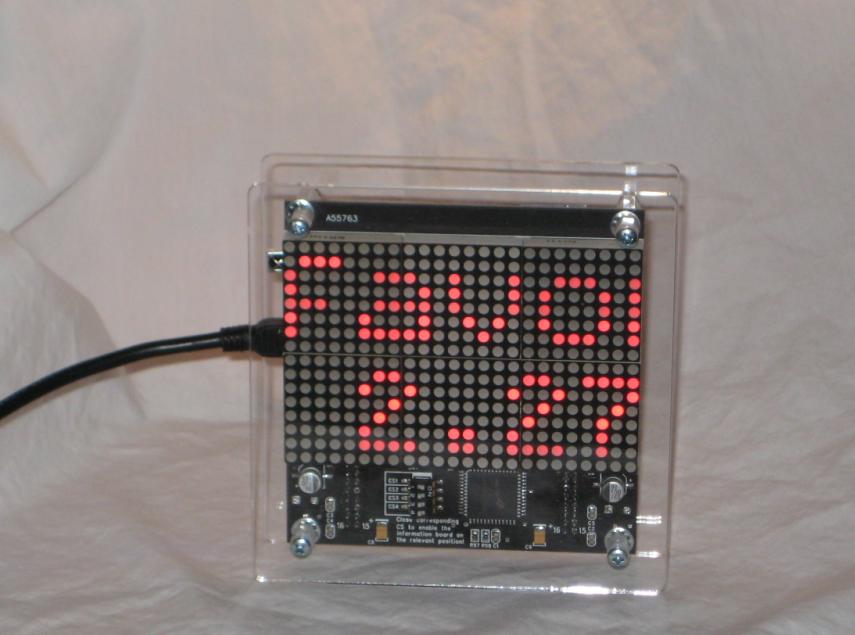
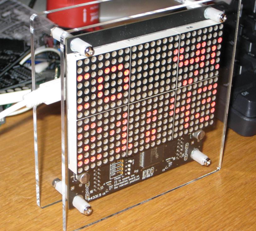
This tutorial shows how to assemble the kit for Wise Clock 2, an open source (hardware and software) project.
A complete Wise Clock 2 kit can be purchased here.
In summary, this is what Wise Clock 2 can do (with the current open source software release):
- display the current time and date;
- read a user-editable file from SD card and display its content (which is usually quotations, hence the "wise" in the name);
- provide alarm functionality;
- provide remote (infrared) controllability.
The Wise Clock 2 kit includes the following:
1. the Duino644 microcontroller board (as a ready-to-solder kit);
2. the 16x32 (red) LED matrix display;
3. the enclosure (two acrylic plates and the required hardware).
The following steps will show how to build Wise Clock 2, including:
- how to solder the Duino644 board;
- how to connect the display;
- how to encase the clock;
- how to get it functional (prepare SD card, set time etc).
Content of Duino644 Kit
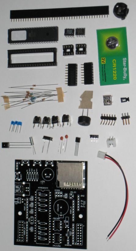
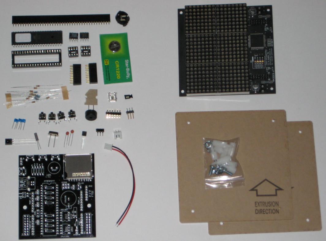
Duino644 is the name of the microcontroller board used in Wise Clock 2.
Duino644 kit contains the following components:
- PCB with the SD card socket soldered on it;
- ATmega644 chip and 40-pin socket for it;
- DS1307 chip (real time controller) in 8-pin DIP package, and a 8-pin socket for it;
- 24LC256 EEPROM chip in 8-pin DIP package, and a 8-pin socket for it;
- CR1220 small coin cell battery, and its plastic holder;
- 16MHz crystal and two 22pF capacitors;
- 32768Hz crystal;
- micro speaker;
- right-angled micro switches (4 pieces);
- USB miniB-type connector;
- 2x8-pin female headers (2 pieces);
- high intensity blue LED in 1206 package;
- 40-pin female header;
- L78L33 voltage regulator;
- JST 2-pin power connector and JST 2-pin power jack with cables;
- infrared receiver IC and 3-pin socket for it;
- 6-pin right-angled male header (for FTDI connector);
- 10K resistors (10 pieces);
- 4K7 resistors (3 pieces);
- 75R resistor;
- 100nF decoupling capacitors (3 pieces);
- 2x3-pin male header (for ICSP connector).
Once we checked we have all the components ready, we can proceed to soldering.
Soldering Duino644 Board
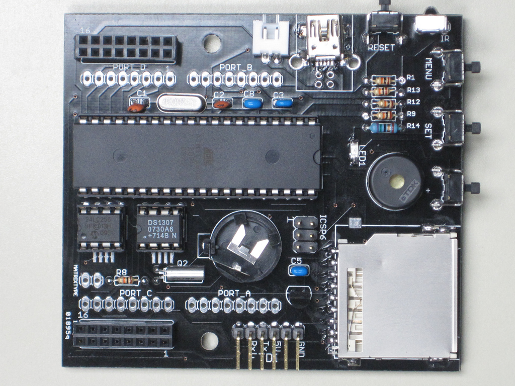
Although not recommended as a started kit, Duino644 should be relatively easy to solder.
Only two components require some previous soldering experience (and good eyes and steady hand) because they are surface-mounted: one is the USB miniB connector, a pretty sturdy passive component, that can take a lot of heat, and the other one is the 2-terminal blue LED, in (one of the) biggest SMD package.
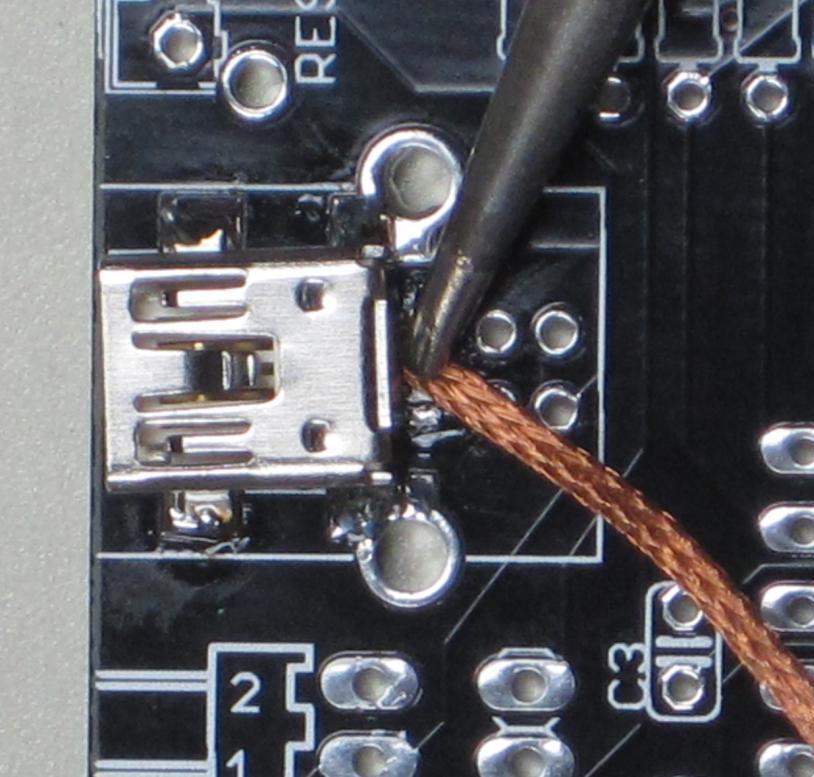
1. (Photo 2.1) Let's start with the USB miniB connector. Position it so that the 2 plastic bumps go into their respective holes in the PCB, and the connector sits closest to the board. Solder the four lateral "ears" first to secure it in place, then continue with the 5 connection pins. Use a magnifier to make sure that no solder bridges are left between those. To remove the possible bridges, use de-soldering wick. Take your time, this is not (such) a temperature-sensitive component.
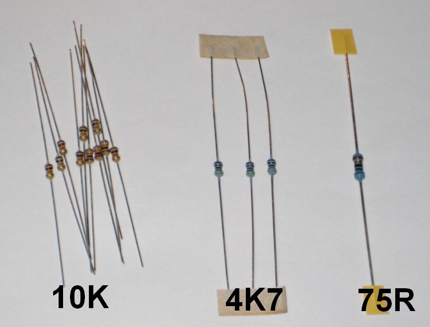
2. Next, we will solder the 75 ohm (purple, green, black, gold, brown) resistor in its place, marked R14.
3. Let's apply the experience gained soldering the SMD connector, to the LED. Orientation of this component is important, so it must be positioned correctly. The cathode (negative terminal) of the LED is marked with a green dot (magnifying glass definitely helps here). On the PCB, the cathode is marked with 3 dots. Melt some solder on the cathode pad, then place the LED's cathode over that pad and solder with the existing blob. Then solder the anode pad.
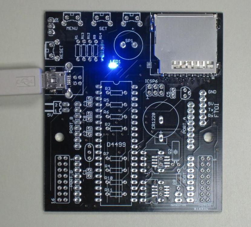
3. (Photo 2.2) At this point we perform a first check, to make sure the board gets power from USB. Just plug in the USB cable and the LED should become bright blue. We have ignition!
4. We will next solder the resistors. Start with the three 4K7 resistors (yellow, purple, black, brown, brown): R5, R6, R7 (orientation is not important). Then place and solder the remaining 10K resistors (brown, black, orange, gold): R1, R2, R3, R4, R8, R9, R10, R11, R12, R13.
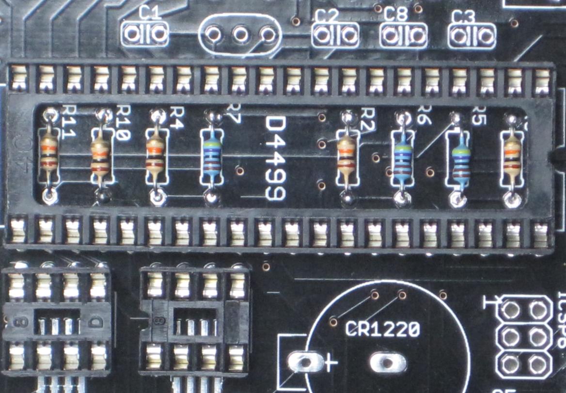
5. (Photo 2.3) Next, place and solder the IC sockets, starting with the big 40-pin one and continuing with the 2 small 8-pin ones. Pay attention to position the sockets so that their notches match those in the silkscreen. This will later help to insert correctly the integrated circuits themselves.
6. Solder the two crystals in the places marked "XTAL" and "Q2", respectively (their orientation is not important).
7. Solder the 22pF capacitors (orange colored) in their places, marked C1 and C2 (orientation not important).
8. Solder the three decoupling 100nF the capacitors (blue colored) in their places, marked C3, C5, C8 (orientation not important).
9. Place and solder the plastic battery holder in its marked position, then insert the coin battery in the holder (positive pole facing the board, negative facing up).
10. Insert and solder the two 2x8 female headers in their marked positions (lower corners of the board). These are the connectors to the display panel.
11. Solder the four micro switches (push buttons) in their marked positions:
- three go on the top part of the board and are used by the clock functionality (set up alarm, accessing menus etc);
- one goes on the left side of the board and is the reset button.
12. Solder the micro speaker in its marked place, at the top of the board (orientation is not important).
13. Solder the 3-pin female header in the upper-left corner of the board (marked IR). This is the socket for the infrared receiver. Insert the IR receiver in the socket, facing the inside of the board. Then bend its terminals 90 degrees, so it ends facing up (in the line of the TV remote control).
14. Insert the L78L33 voltage regulator chip, paying attention that its orientation matches that on the silkscreen.
15. Solder the 6-pin right-angled male header in the place marked FTDI.
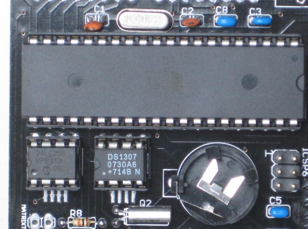
16. (Photo 2.4) Insert the integrated circuits in their respective sockets, paying special attention to their orientation. The big ATmega644 chip has the notch facing towards the top of the board. The other two small chips have the notches towards the bottom of the board. DS1307 must be place in the socket close to the coin battery. 24LC256 must be placed in its socket close to the bottom edge of the board, as marked.
At this point, the Duino644 microcontroller board is assembled and ready for testing (or use).
It should look like the one on photo 2.5.
Next, we will plug the display board
Then, we will program the ATmega644 chip with the latest Wise Clock sketch, through the Arduino IDE.
Plug in the Display and Encase the Clock
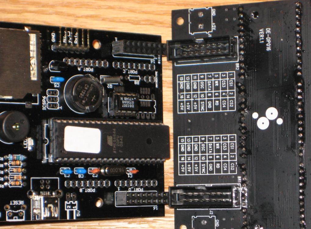
Insert the freshly minted Duino644 into the back of the display panel (as in the attached photo 3.1), making sure the two sets of connectors (male headers on the display panel and female headers on the Duino644 board) plug into each other. Press gently until the connectors are fully plugged and make sure the two boards are parallel. This is the only attachment between the two boards (there are no fasteners or screws), and it will be protected by the enclosure.
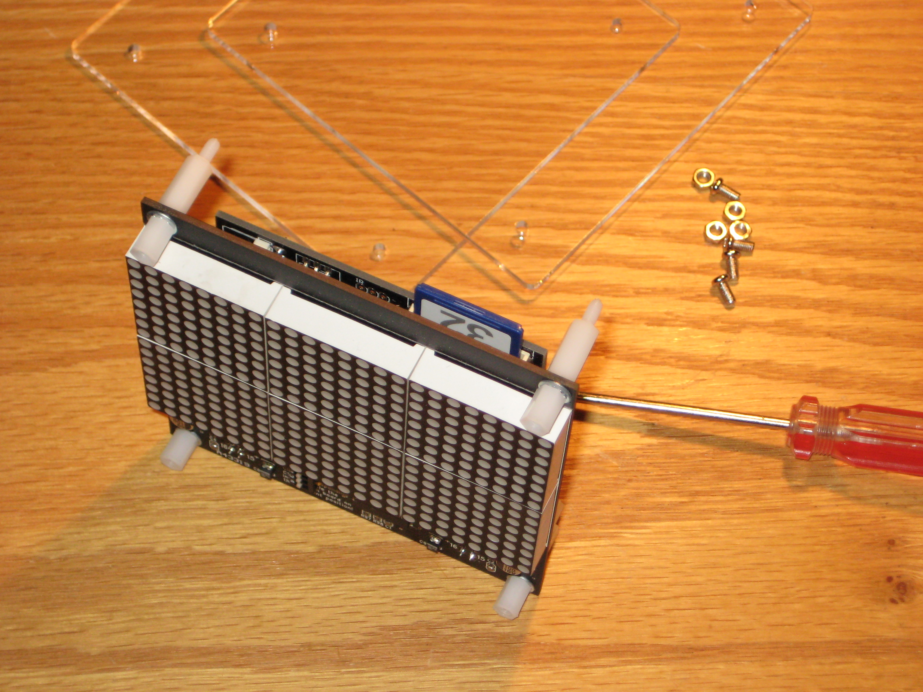
The enclosure consists of two plexiglass plates sandwiching the two boards (Duino644 and the display). These plates are hold in place with screwed-together spacers (and screws and nuts).
Let's proceed with attaching the white nylon spacers (standoffs) on both sides of the display panel, in the four holes in the corners. The shorter spacers go in front of the display, the longer one are screwed in on the back side (as shown in photo 3.2). Note the washers used with the short spacers, they create a small space between the front plexiglass panel and the LED display itself, so they don't touch.
After the spacers are tightened, place and screw in the front plexiglass plate, then go on to the back plate. Tighten all screws and nuts while the enclosure sits on an horizontal surface (desk), to make sure the assembly it is sturdy and there is no torsion.
After we prepare the SD card, we should be ready to test the clock.
Prepare the SD Card
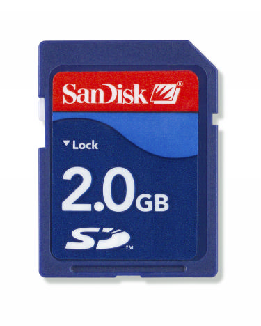
Wise Clock 2 displays quotations retrieved from a text file stored on the SD card (photo 4.1). The name of this file is "quotes.txt" and is part of the zip file containing the sketch (download from here). It can also be created from scratch, as a ASCII text file, to include one's favorite quotations, in the desired sequence.
The only restriction (in the software) is the length of the line, which cannot exceed 150 characters.
Lines are separated with CR/LF (carriage return/line feed, or ASCII codes 13/10).
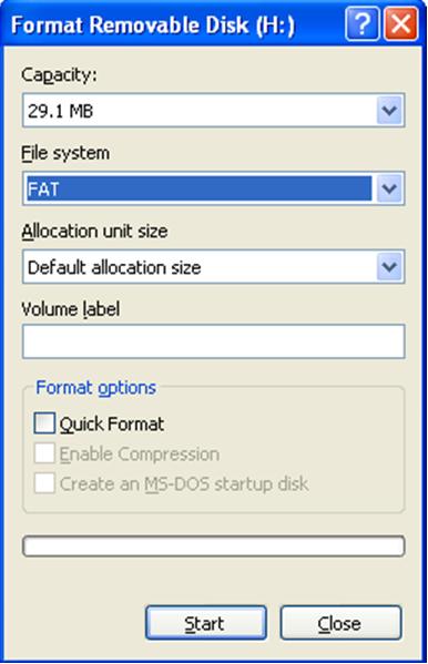
The SD card must be formatted as FAT (also known as FAT16). This can be done in Windows, by selecting "Format" in File Explorer, which displays the dialog box shown in photo 4.2.
Note: The maximum capacity that FAT16 can handle is 2GB.
Another important file on the SD card is "time.txt", required for setting up the clock.
"Time.txt" file contains a line like this:
12:22:45Z2009-11-14-6
which needs to be modified to reflect the current time and date.
When the clock is powered (with the SD card inserted), the time and date read from this line will be set in the real time clock as the current time and date, respectively. After the clock is (automatically) set on power-on, the file "time.txt" is marked as deleted, so that next time the clock is powered the file is not found.
The two files, quotes.txt and time.txt, can be found the zip file containing the sketch.
Program Duino644 With the "Wise Clock 2" Sketch
1. Download the Wise Clock sketch from the specified location.
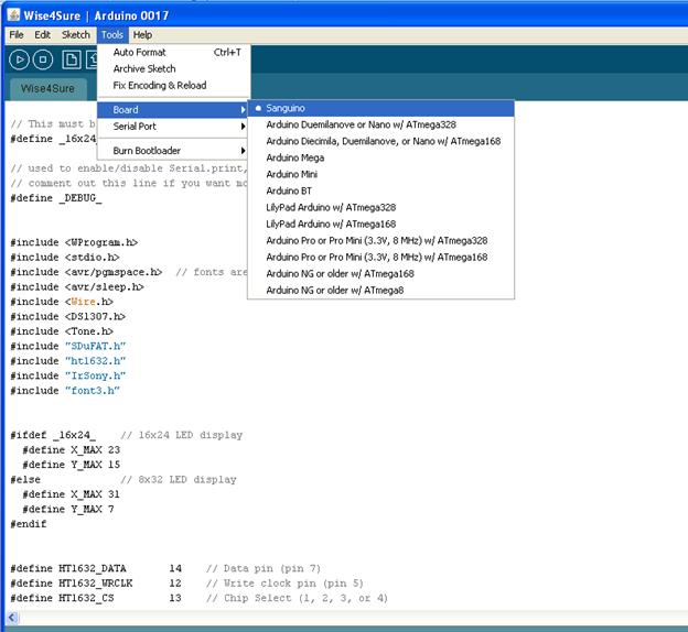
2. Add the Sanguino libraries to your Arduino IDE. (Duino644 is a flavor of Sanguino, if you will. It is compatible with Sanguino and uses the same libraries developed by Sanguino team to support their own board. And we thank them.)
3. Launch the Arduino IDE and select "Sanguino" as the target board (see photo 5.1).
4. Open the Wise Clock sketch in Arduino IDE and compile it.
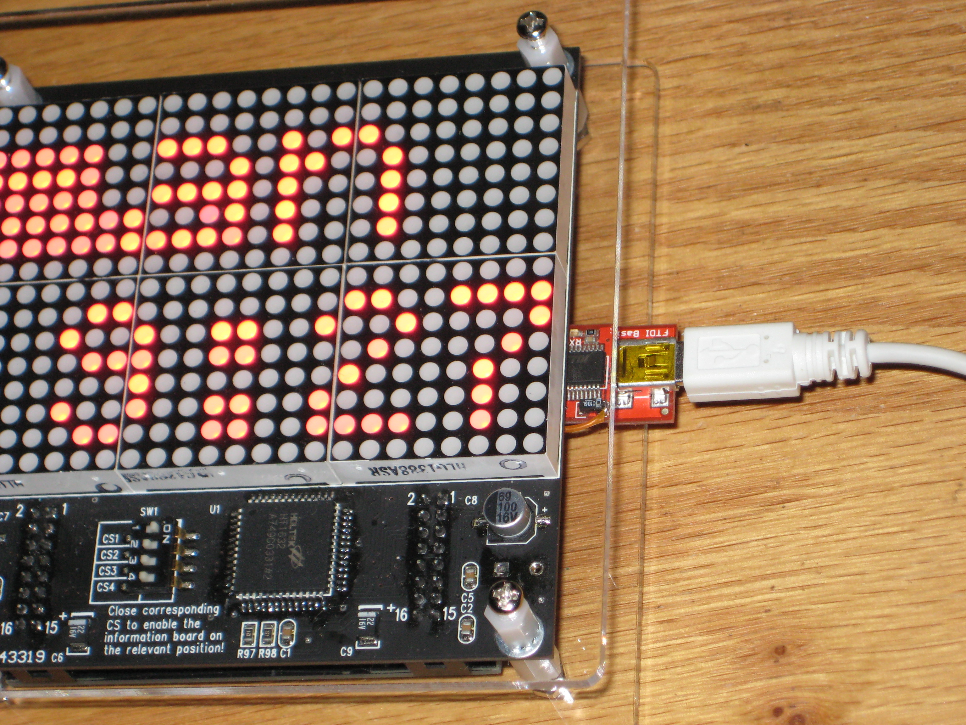
5. Using an FTDI cable or FTDI breakout (connected between the USB and the 6-pin FTDI connector on the Duino644 board), upload the compiled sketch (see photo 5.2).
Note: The above mentioned code was tested and confirmed to work with Arduino IDE version 17.
Power the Clock and Enjoy It
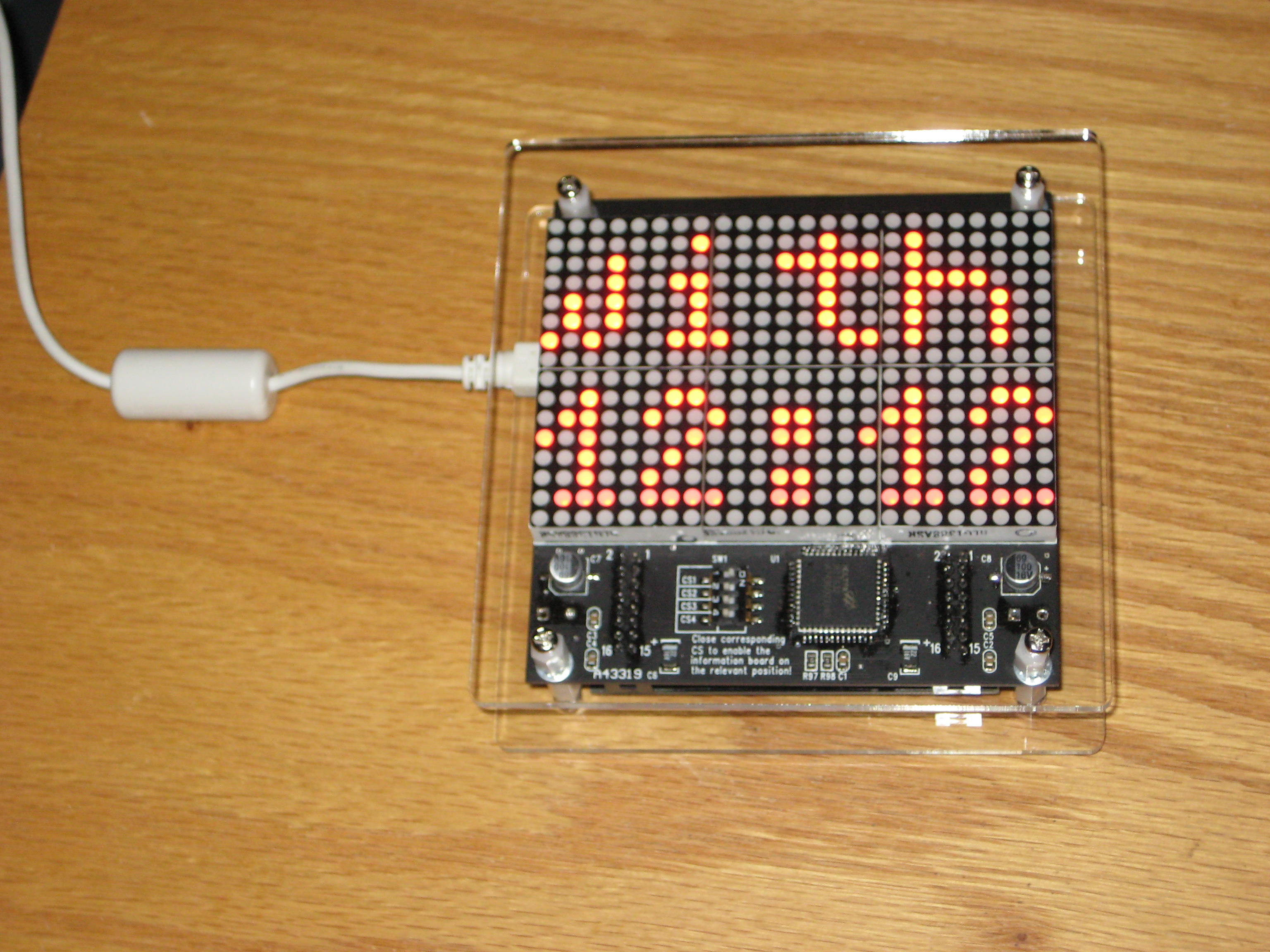
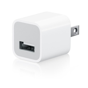
Now that the clock is assembled and programmed, it is time to power it up with the USB cable, preferably from an USB adapter, like those used to recharge iPhones and other mobile devices (photo 2).
Enjoy it!
Enjoy it!