Arduino for Nerf: Ballistic Chronograph
by MakersBox in Circuits > Arduino
18276 Views, 76 Favorites, 0 Comments
Arduino for Nerf: Ballistic Chronograph
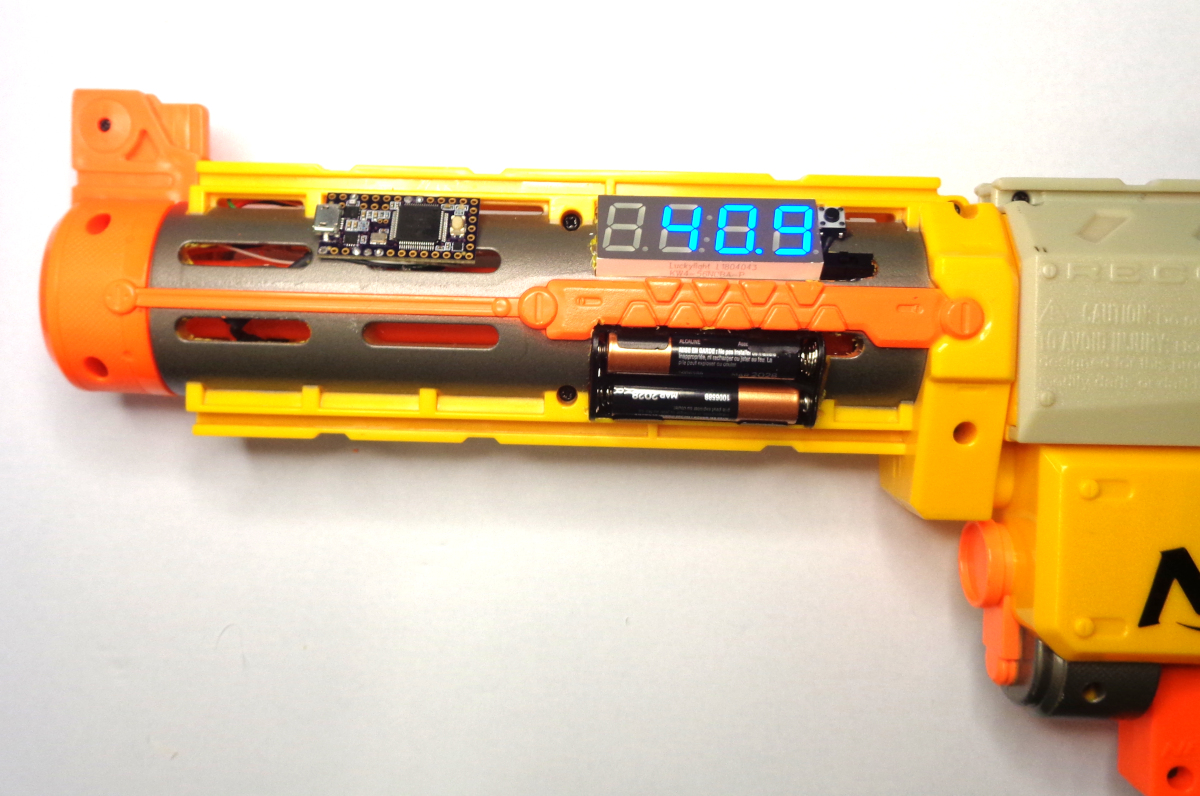
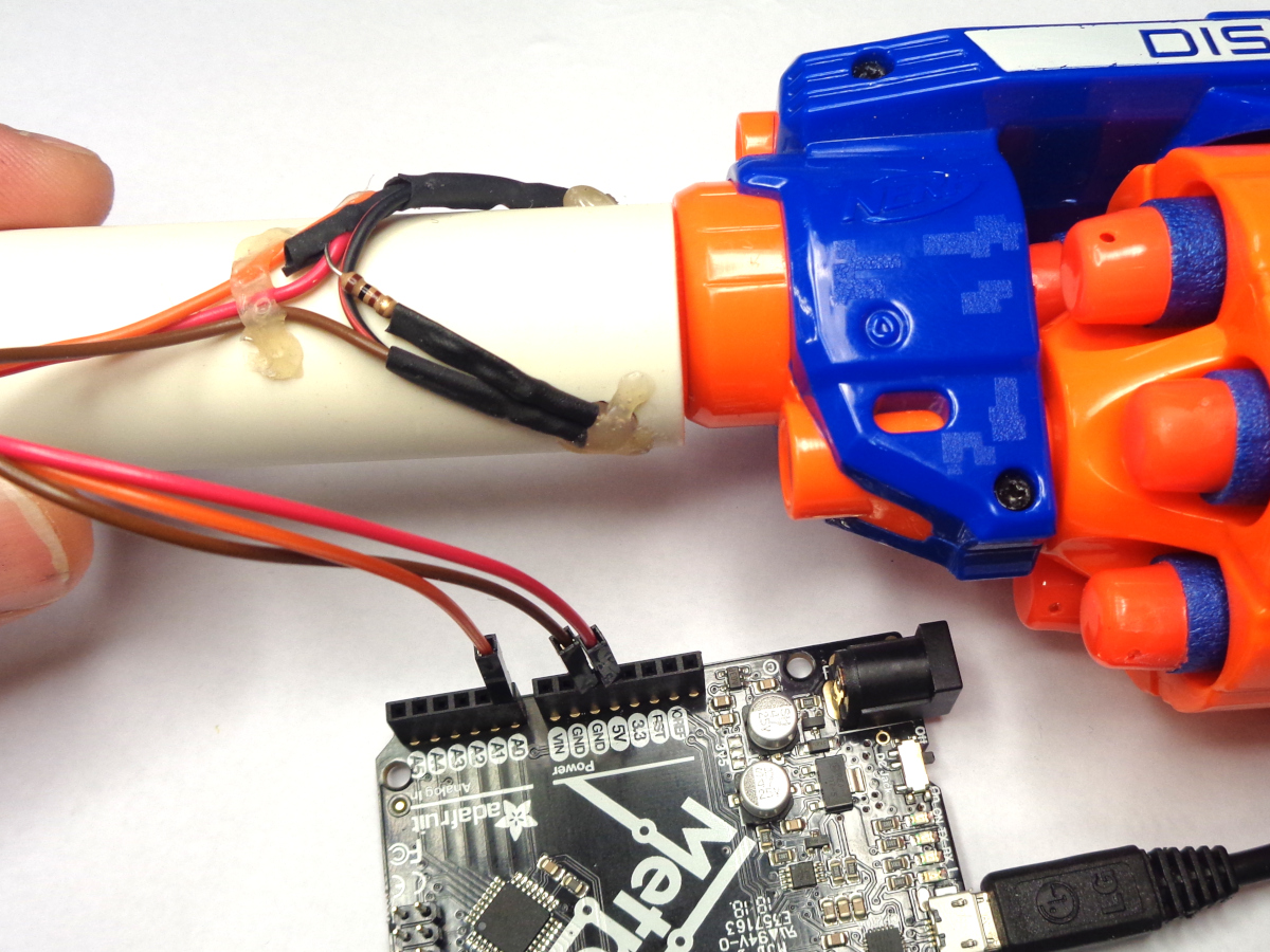
Arduino is an amazing tool for Makers, and as I got back into Nerf and started modding, I began to wonder what I could do with Arduindo to help determine the effect of modifications. Take a look at any older Nerf video and you will find a kid firing darts on their lawn over a tape measure. Take a look at any recent Nerf video, and you will see them shooting darts through an expensive ballistic chronograph. Why not apply Arduino to help us with Nerf mods, both in measuring performance and in controlling operation?
Using this project to measure dart speed as an example, I looked at the effect of removing the air restrictor and adding a stronger spring to a thrift-store Modulus Modulator. Either mod by itself equated to 20 to 25% improvement. Together, however, an exponential increase of almost 80%!

The cover photo is just a teaser example of a chrongraph integrated with a barrel attachment and display. We will first focus on detection portion and get the readings on a serial console. And yes, this poor old unmodified thrift-store Recon is shooting a miserable 40 fps. Once we know what we are starting with we can start modding to see the effects . ..
There are already a number of cool projects like this out there. My goal for this one was to make it fundamental enough to understand and easy enough for a beginner to accomplish. You'll have to judge if I succeeded, or let me know how to make it better.
How Does It Work?
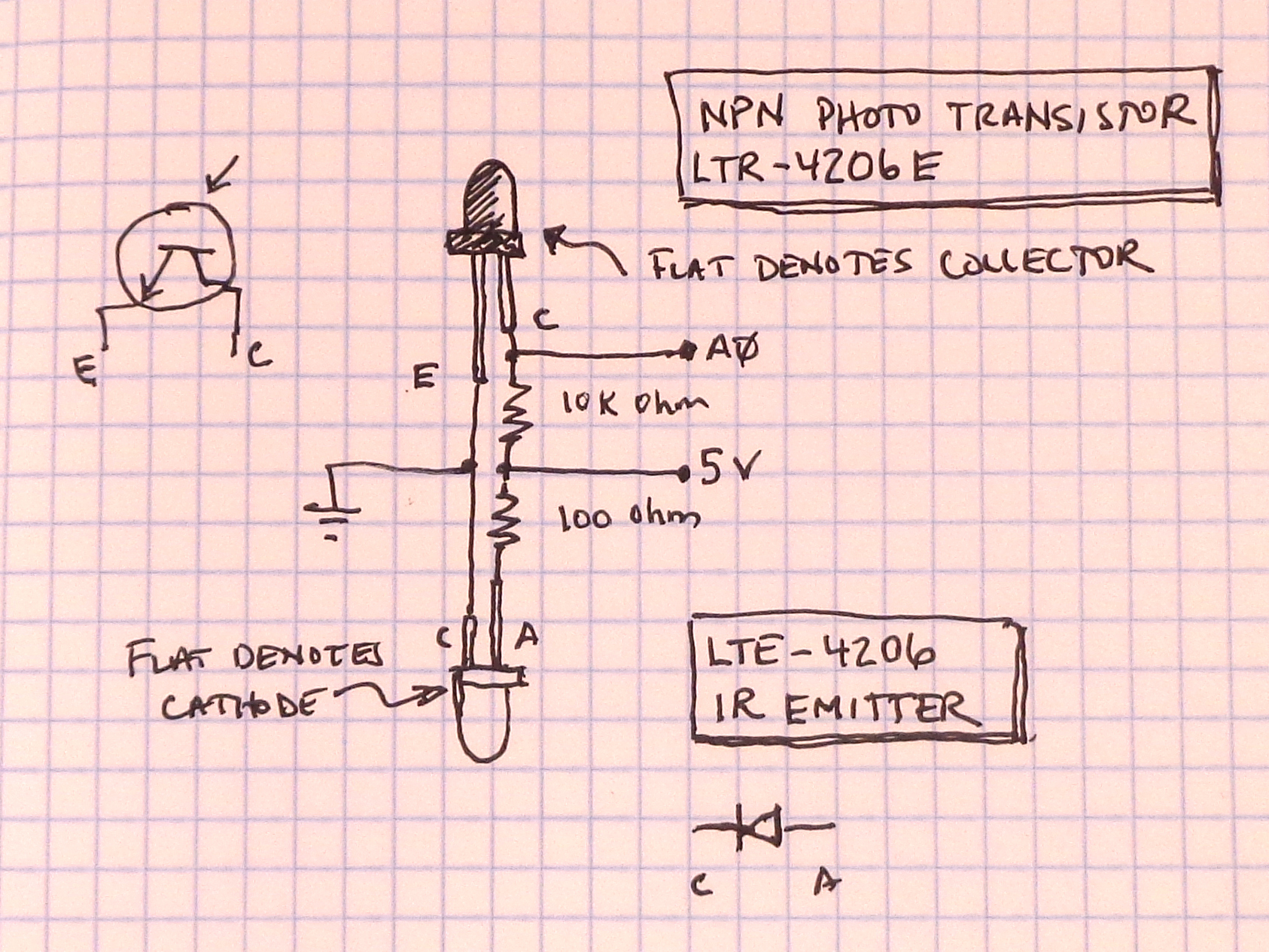
There are a number of methods to measure the speed of an object. We want easy, reliable, and inexpensive. My choice is an infrared emitter detector pair. The microcontroller will sense when an object enters the beam, and when the object leaves the beam. If we know the length of the object, and measure the time it takes, we have all the ingredients needed calculate velocity.
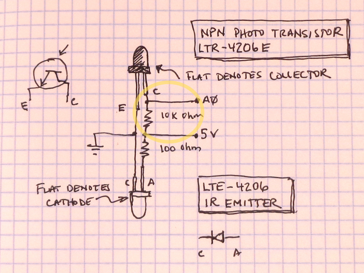
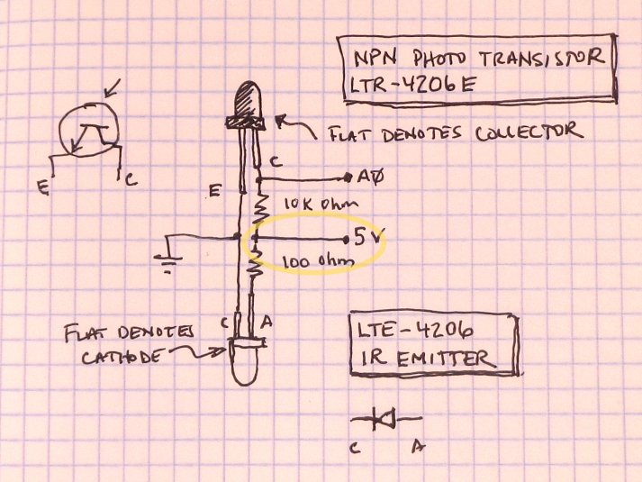
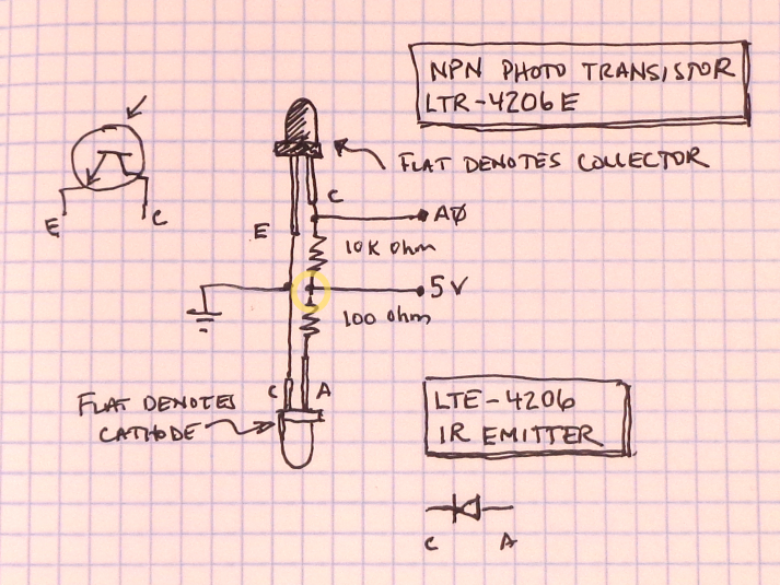
The photo transistor works as a switch, but instead of a signal being applied to the base to allow current to flow from the collector to the emitter, light is applied. The dark cover means only infrared light will work. We are using a small resistor to pull-up the signal to 5 volts, so when the IR light is detected, current flows through the transistor, allowing the signal to fall toward 0 volts. It is a bit counter intuitive, but it works. Learn more about how transistors work at https://www.electronics-tutorials.ws/transistor/tran_4.html.
Parts and Tools
To start with, we just want to wire something up to test it on the bench. Later, we can integrate it into a stand-alone solution ready for the battlefield.
Parts:
- Arduino Uno or compatible microcontroller, recommend:
- Adafruit Metro, https://www.digikey.com/short/pzf5rv) or
- Adafruit ItsyBitsy, https://www.digikey.com/short/pz2pc0 (doesn't have headers, so wires will have to be soldered to it).
- 1 ea., NPN Photo Transistor
- Lite-On LTR-4206E, https://www.digikey.com/short/pzf5cn or
- Everlight PT204-6B, https://www.digikey.com/short/jw9ht0
- 1 ea., IR Emittor
- Lite-On LTE-4206, https://www.digikey.com/short/pzf57f or
- Everlight IR1503, https://www.digikey.com/short/jw9m1r
- Resistors
- 100 ohm 1/8 or 1/4W generic, https://www.digikey.com/short/q72818
- 10K ohm 1/8 or 1/4W generic, https://www.digikey.com/short/7thw1q
- Heat shrink assortment
- 12" Jumper wire assortment, Adafruit 1955, https://www.digikey.com/short/pzf5pb
Tools:
- Soldering iron, solder, safety glasses
- Wire snips (recommend Hakko CHP-170, https://www.digikey.com/short/ptnm3p)
- Wire stripper (recommend Hakko CSP-30-1, https://www.digikey.com/short/pzf55b)
- Hot air gun (recommend SparkFun Heaterizer, https://www.digikey.com/short/pzf5mj)
- Hot glue gun
Let's Begin . . .
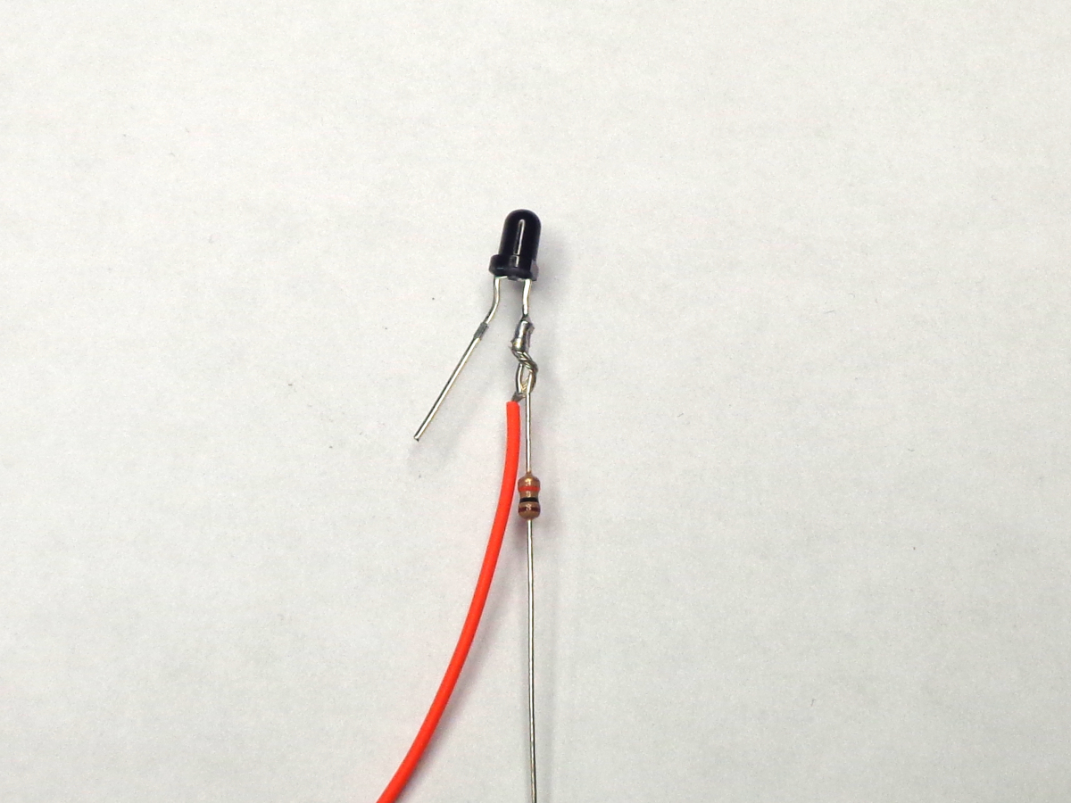
The photo transistor is the dark package.
The short leg is the collector. We are going to attach the sensor wire and a 10K ohm pull-up resistor to it.
- Select a jumper wire with a color other than black or red (orange in the photo looks red).
- Cut one end off near the terminal and strip about 1/2" of insulation off.
- Twist the sensor wire with the 10K resistor around the short leg and solder them together.
- Slide a piece of heat shrink over the wire and resistor, leaving the resistor leg sticking out, and shrink.
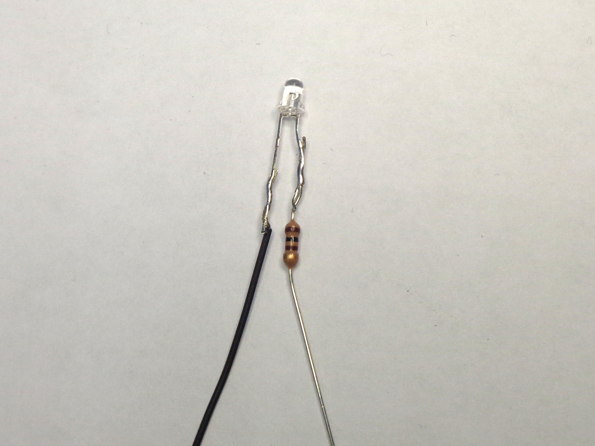
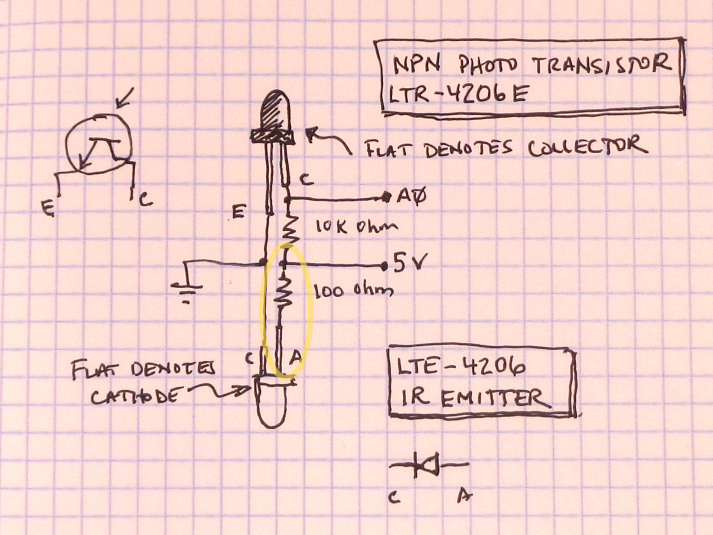
Lets switch over to the IR emitter.
We are going to attach a 100 ohm current-limiting resistor to the anode, or plus side.
- Twist the 100 ohm resistor around the anode (long) leg and solder in place.
- Take a black jumper wire, and cut both ends off so it is about 6" in length (use regular wire if you have it).
- Strip 1/2" off both ends.
- Wrap one end of the black wire around the cathode (short) lead and solder it in place.
- Cover the exposed leads of the emitter with heat shrink (leave the resistor end out).
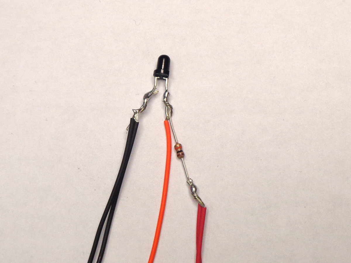
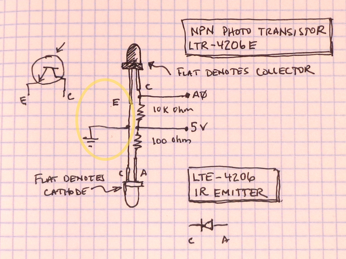
We are going to combine ground and power lines to the IR LED starting with the black ground wire.
- Take a black 12" jumper and cut one end off near the terminal.
- Strip off 1/2" of insulation.
- Place a small piece of heat shrink on the 6" black lead before soldering.
- Twist it together with the 6" black wire from the IR LED and solder to the emitter (short) leg of the transistor.
Combine a 6" red wire and 12" red wire to the 10K resistor:
- Strip and tin both ends of the red wire.
- Take a red jumper wire and cut both ends off so it is about 6" in length (use regular wire if you have it).
- Strip 1/2" off both ends.
- Take a red 12" jumper wire and cut one end off near the terminal.
- Cover exposed metal with heat shrink.
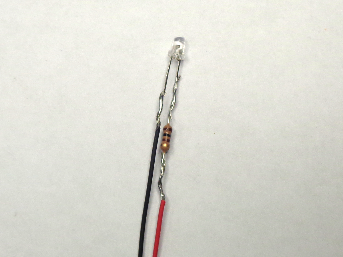
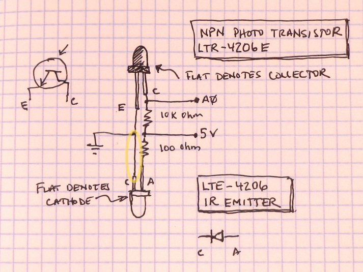
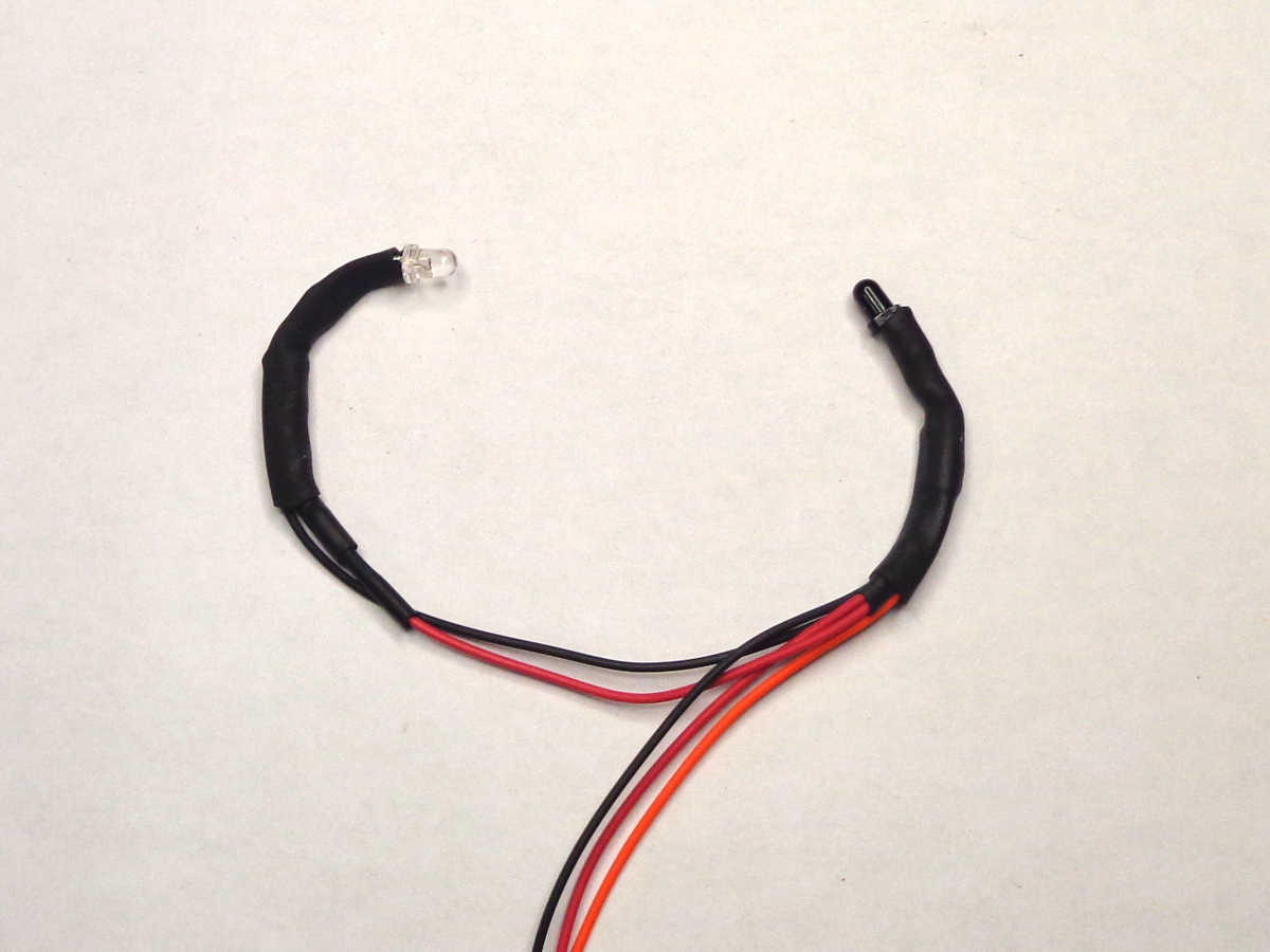
We are going to finish this end of the harness by connecting the 6" wires to the IR emitter, starting with black
- Place a piece of heat shrink on the black 6" wire and solder to the short leg (cathode) of the LED.
- Slide the heat shrink up and heat.
And now the power side (red):
- Place a piece of heat shrink on the red 6" wire and solder it to the 100 ohm resistor.
- slide the head shrink up and heat.
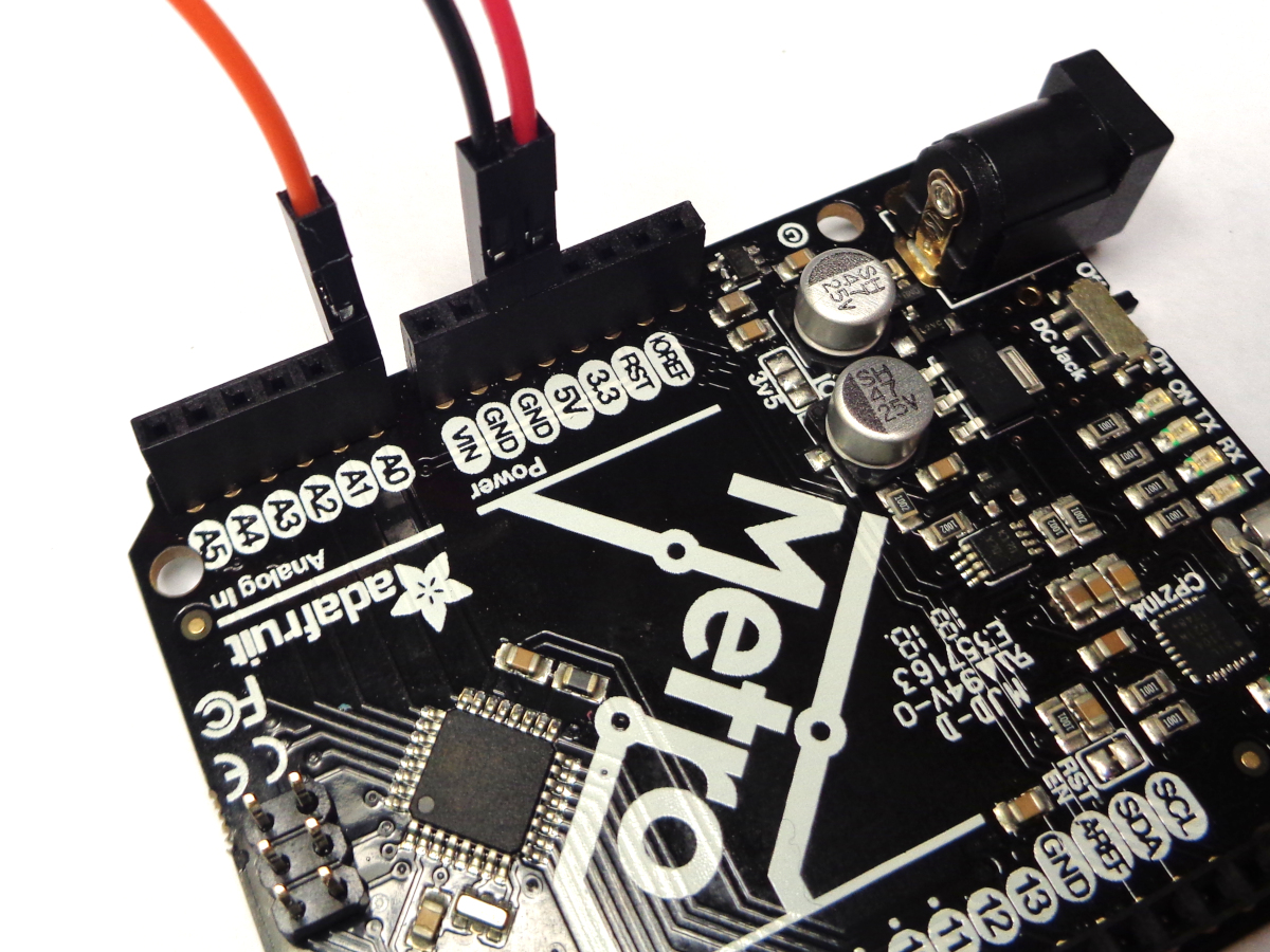
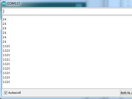
Time to test out your work. Make the following connections to your Arduino board:
- Red wire to 5V.
- Black wire to GND.
- Color wire to A0.
If you are new to Arduino, learn how to download, install, and set up the IDE here: https://learn.adafruit.com/lesson-0-getting-started/installing-arduino-windows
If you are using the IstyBitsy, see https://learn.adafruit.com/introducting-itsy-bitsy-32u4/ for setup, and solder wires to the correct pins.
Attach your Arduino and launch the Arduino IDE
- [Tools] -> [Board] -> Select the flavour of Arduino you are using.
- [Tools] -> [Port] -> Select the port (usually the highest number).
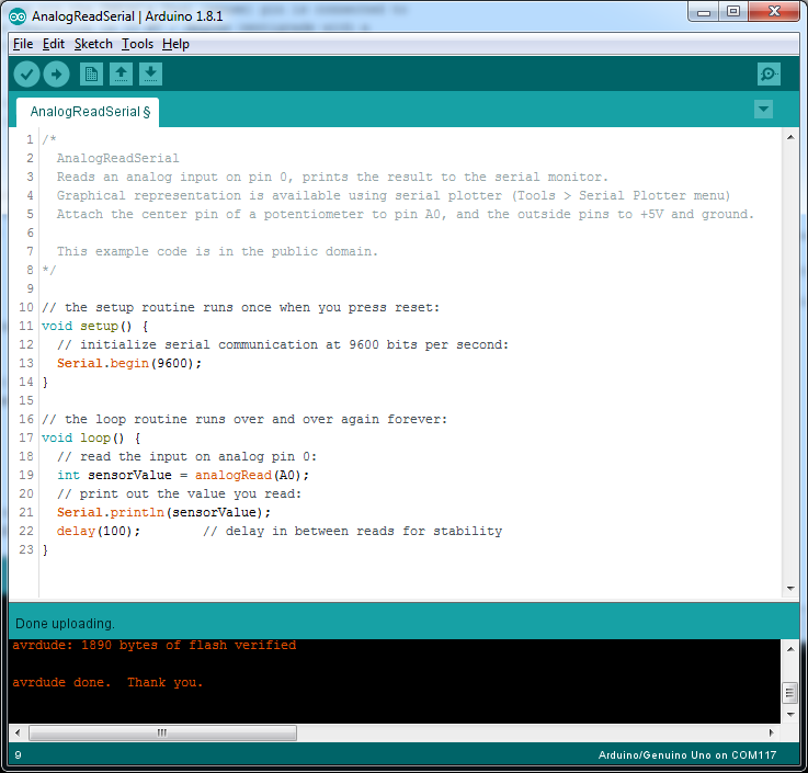
- [File] -> [Examples] -> [Analog] -> [AnalogReadSerial]
- Upload to your board.
- Click the "Serial Monitor" icon in the right corner.
With any luck, you are seeing a stream of values coming in. These are 10-bit analog values so will range from 0 to 1023. Point the IR LED toward the transisor and verify you see a change:
- When the photo transistor is exposed to light, it allows current to pass and the signal will drop towards 0.
- When the photo transistor does not see IR, it stops the current flow allowing the signal to go high.
If you are not getting expected changes, here are some things to check:
- Are the jumpers connected to the correct pins (5V, GND, A0)?
- Is the IR LED on?
- It should be slightly warm to the touch.
- A cheap cell phone camera will show IR light nicely.
- If it is not on, it is likely wired backward.
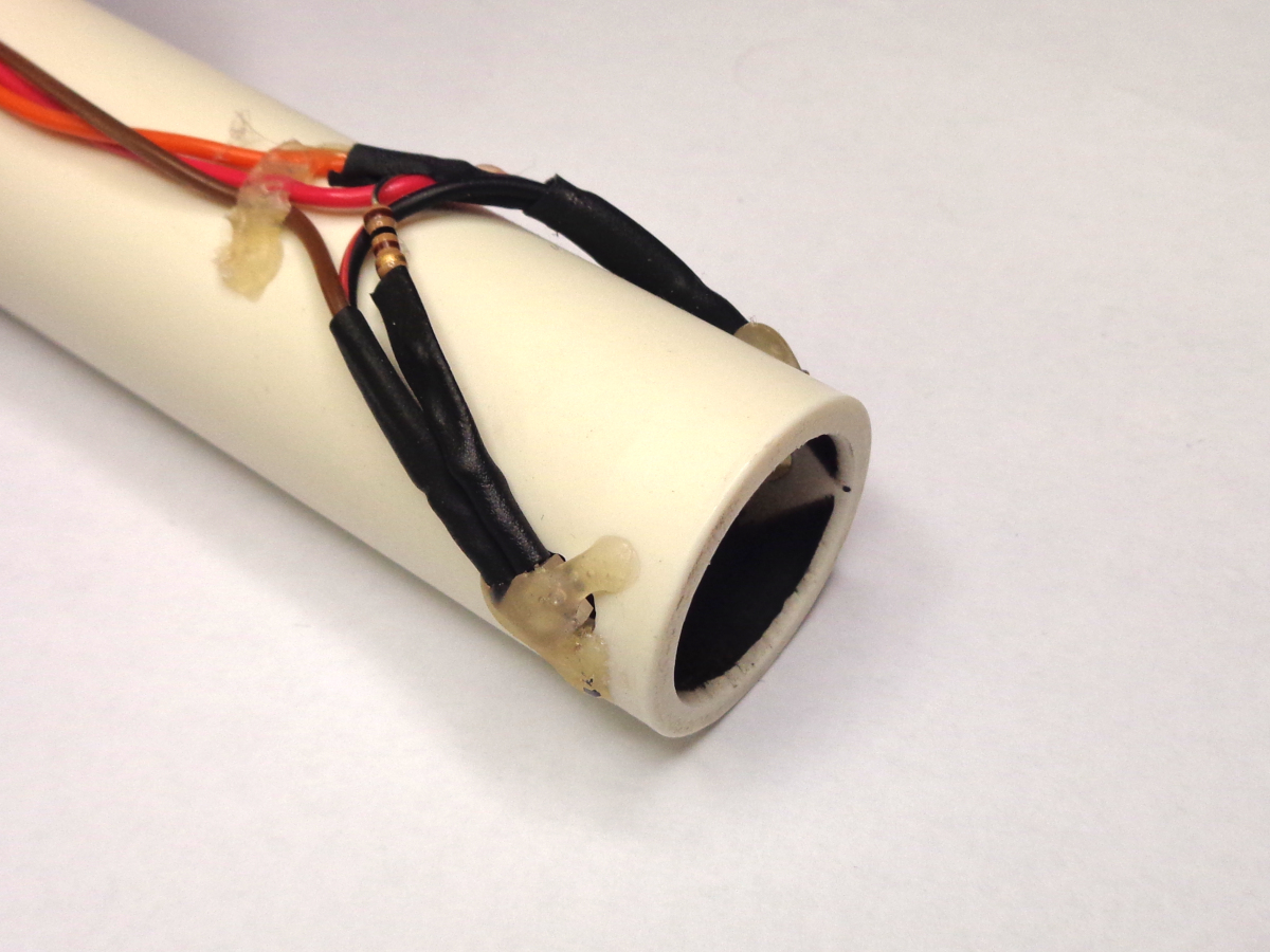
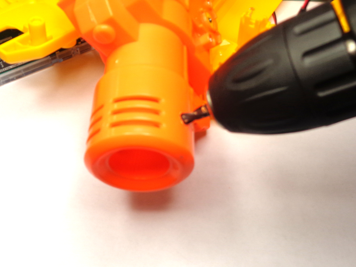
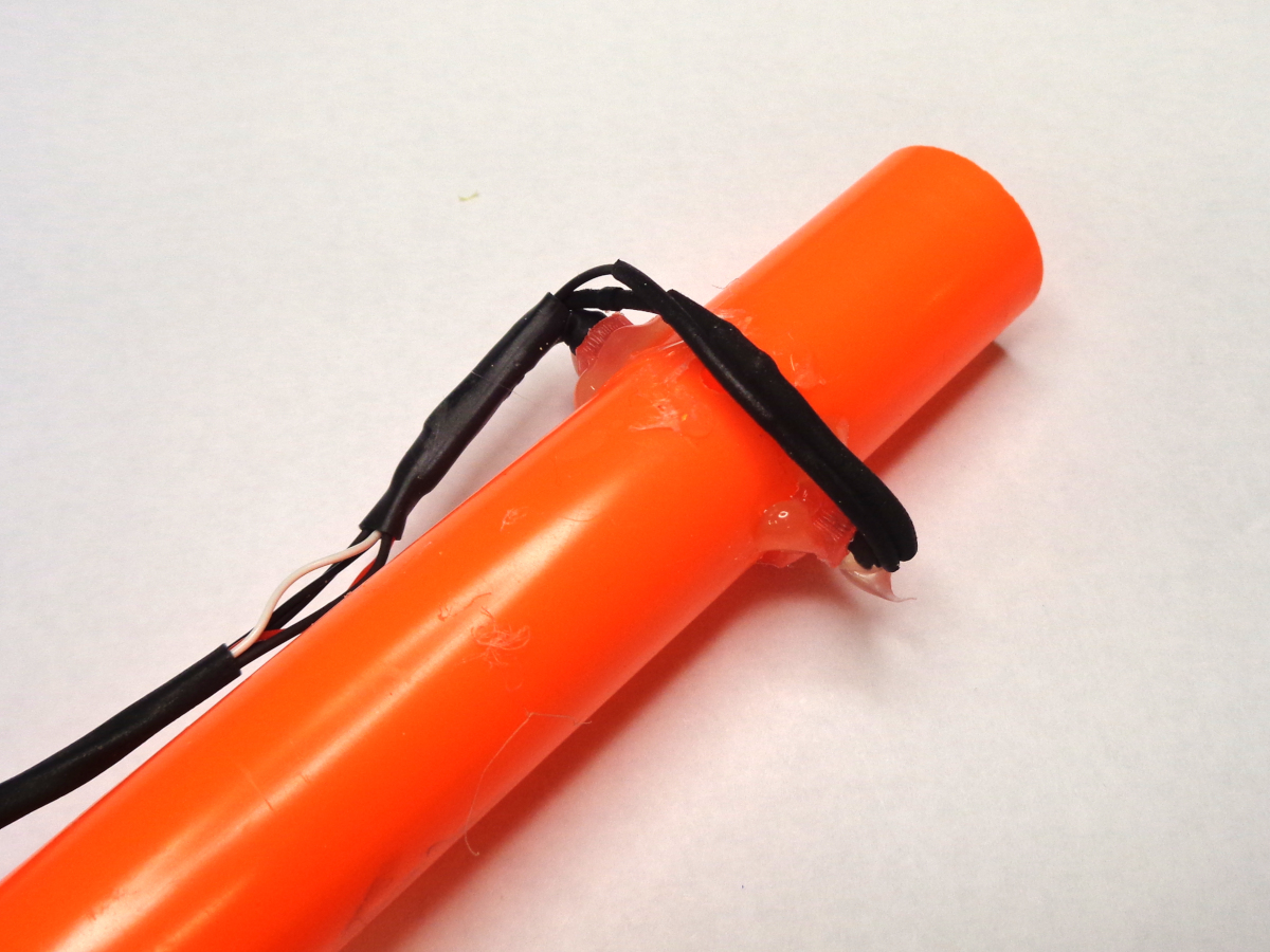
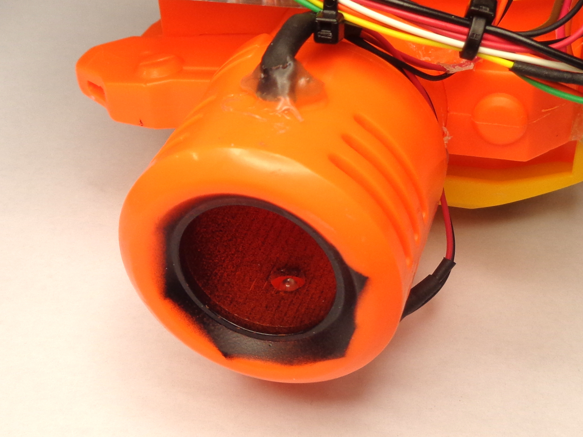
Time to install the sensor rig into something usable. This can be:
- A short section of 3/4" PCV pipe.
- Barrel of a Nerf blaster.
- A removable Nerf blaster barrel attachment.
The one big trick I have learned the hard way is that the both the dart and the plastic will reflect IR light, giving spurious values as the dart passes by. The way to avoid this is to spray flat or matte black inside the barrel to absorb the scattered light.
- Drill a hole large enough for the LED and transistor through the middle of the tube on both side.
- Hot glue the transistor and LED so they are pointing directly at each other.
- Reconnect to the Arduino and test as in the previous step.
- Using a dart, ensure that the values are well above half (>700) with the dart present, and well below half (<300) with the dart removed.
- Check the alignment if you are not getting good values. The phone camera can show if the IR is hitting the transistor.
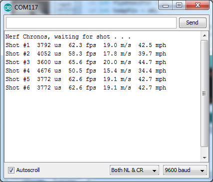

Time for a program to calculate velocity. The analog reading is great for testing and troubleshooting, but when we are looking for darts at full speed, we only need to see when the signal crosses the half-way point, which is where interrupts come in. For Arduino, there are two types of interrupts, hardware interrupts (on pins 2 & 3 only) that can detect rising or falling edges, and pin-change interrupts that works on any pin but requires us to figure out what happened. By doing a quick digitalRead() on the pin when the interrupt occurs, we can decipher if the dart is there or not, and thus whether it is entering or exiting. The difference in time between the entry and exit and the length of the dart give us the data needed to calculate velocity.
Note: This method is only valid if the darts are the same length. If you use modified darts ("Stephans"), you will either need to change the dart length in the program, or add a second emitter/detector pair at a specific distance. The farther apart, the more accurate the timing will be.
If you want to dig deeper into how interrupts work and how to use them, check out https://gammon.com.au/interrupts.
You should be able to copy and paste this code into the Arduino IDE, or download and open the attached file.
int sensorPin = A0;        // must be pin A0 to A5 for interrupt PCINT1_vect signal
int shot_count = 0;
long time1_us = 0;         // dart enters gate
long time2_us = 0;         // dart exits gate
long interval_us;          // flight time between entrance and exit
float dartLength_mm = 72;  // mm
float speed_fps = 0;       // feet per second
float speed_mps = 0;       // meters per second
float speed_mph = 0;       // miles per hour
float ave_fps = 0;         // average feet per second
bool flag = false;         // dart exits gate


void pciSetup(byte pin){
  *digitalPinToPCMSK(pin) |= bit (digitalPinToPCMSKbit(pin));  // enable pin
  PCIFR  |= bit (digitalPinToPCICRbit(pin)); // clear any outstanding interrupt
  PCICR  |= bit (digitalPinToPCICRbit(pin)); // enable interrupt for the group
}


void setup() {
  // pin setup
  pinMode(sensorPin, INPUT);  // should have external pull-up or use INPUT_PULLUP
  pciSetup(sensorPin);

  // Open serial coms to console
  Serial.begin(9600);
  Serial.println("Nerf Chronos, waiting for shot . . .");
}


ISR (PCINT1_vect) { // handle pin change interrupt for A0 to A5 here
  if (digitalRead(sensorPin)) { // HIGH if dart present
    time1_us = micros();
  }
  else {                        // LOW when dart exits
    time2_us = micros();
    flag = true;
  }
}


void loop() {
  if (flag){ // dart has exited gate
    shot_count += 1;
    interval_us = time2_us - time1_us;
    speed_fps = dartLength_mm / interval_us / 25.4 / 12 * 1E+6;               // feet per second
    speed_mps = dartLength_mm / interval_us / 1000 * 1E+6;                    // meter per second
    speed_mph = dartLength_mm / interval_us / 25.4 / 12 * 1E+6 / 5280 * 3600; // miles per hour

    Serial.print("Shot #");
    Serial.print(shot_count);
    Serial.print("  ");
    Serial.print(interval_us);
    Serial.print(" us  ");
    Serial.print(speed_fps, 1);
    Serial.print(" fps  ");
    Serial.print(speed_mps, 1);
    Serial.print(" m/s  ");
    Serial.print(speed_mph, 1);
    Serial.println(" mph  ");
    flag = false; // reset gate
  }
}
Testing with your finger should trigger at a few feet per second. Dropping a dart through with gravity should be a little faster.
The pictured data is from an unmodified thrift-store Disruptor shooting a pretty solid 60 fps. Get your blaster out and start collecting data!
Downloads
Going Farther . . .

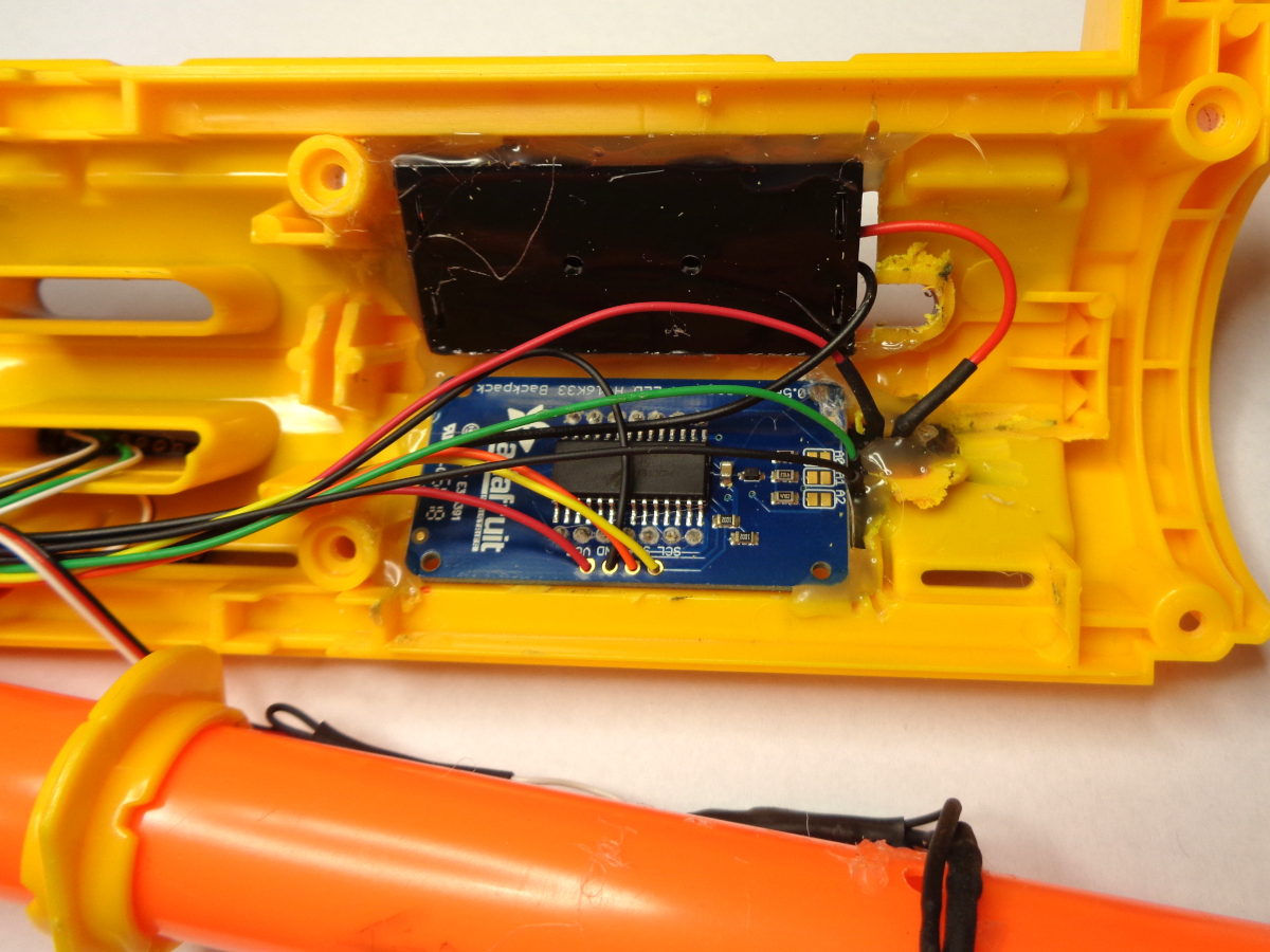
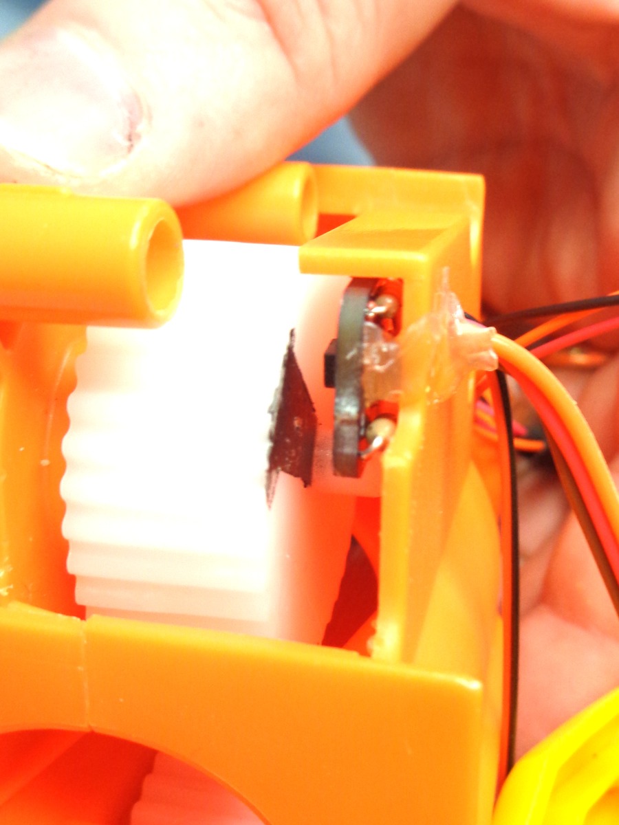
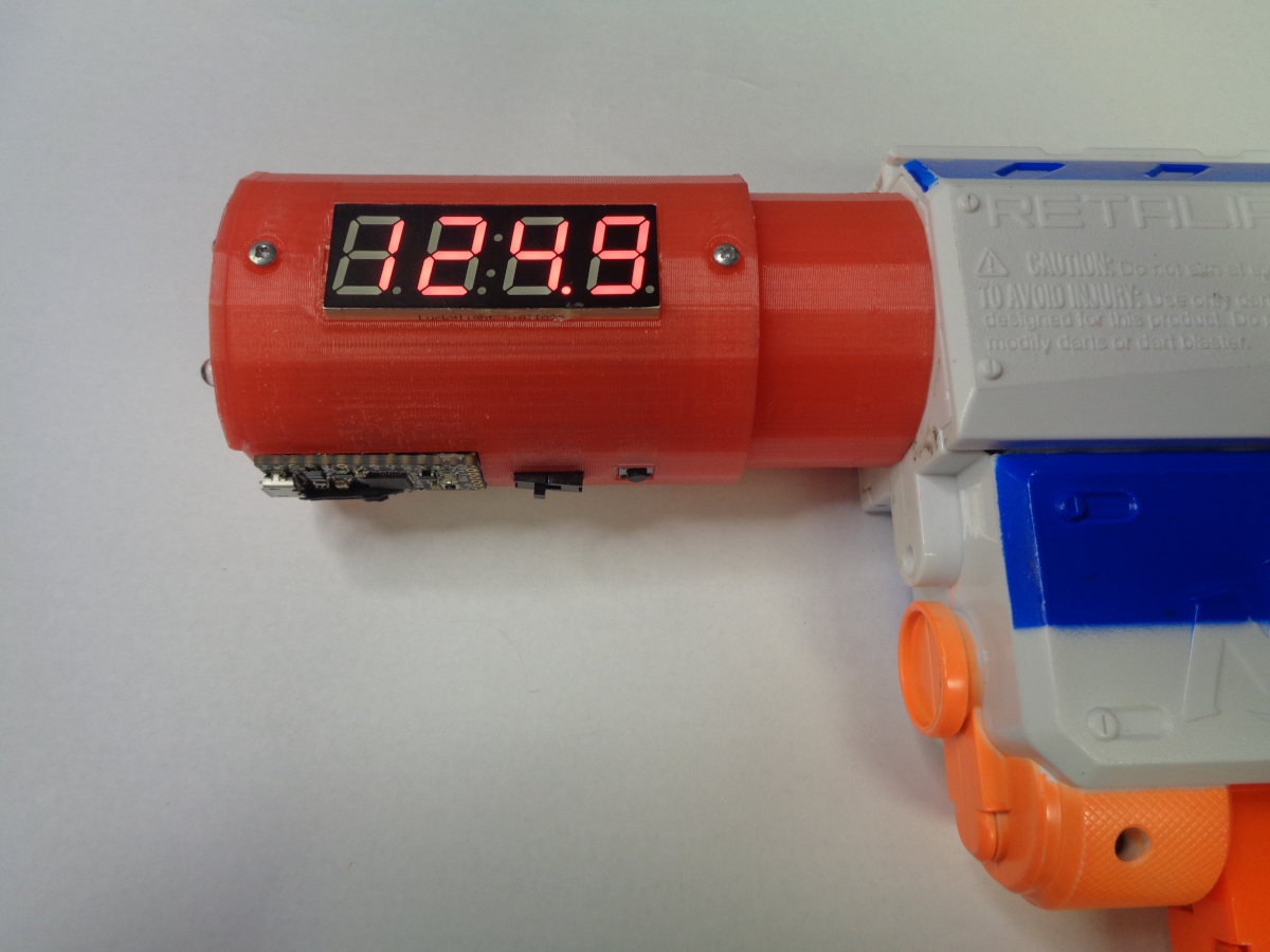
We have obviously just scratched the surface of what we can do with Arduino and Nerf. Continuing with this project, you can:
- Add a display to show velocity and shot count..
- Add a button to reset counter or change settings..
- Integrate a smaller microcontroller like an Adafruit ItsyBitsy.
- Battery power for portability.
Going further, you can instrument a number of other parameters to help determine performance:
- Flywheel speed.
- Battery voltage.
- Motor temperature.
And, finally, we could use Arduino to control a number of things:
- Strobe some LEDs to simulate muzzle flash.
- Mosfet transistor control of motors.
- PWM speed control for rate of fire.
- Single, burst, or auto fire selection.
- Biometric locks.
- Phased plasma rifle in the 40 watt range.
And yes, that tired old thrift-store Retaliator in the last picture hit 124 fps with some tweaks. It averages about 100 fps and was summarily banned from the office wars because "it hurts". Knowledge is power . . .