Arduino Controlled Animatronic Wooden Head (reading Lamp)
by rosemarybeetle in Circuits > Arduino
31826 Views, 139 Favorites, 0 Comments
Arduino Controlled Animatronic Wooden Head (reading Lamp)


This head is a reading lamp which can be adjusted for direction of lighting, and dimmed as required.
This Instructable combines Arduino programming, some simple electronics, carving with hand and power tools, mechanical control and a bit of woodwork. Apart from the Arduino and a few components it is mostly made from reclaimed materials.
I am rather pleased with it.
What's in this instructable
I have included the main circuit and controlling Arduino programme (the sketch), and issues that arose, but I have also tried as much detail of the other (physical) making processes involved, so hopefully some of that stuff may be useful if you are building something in a similar way.
This project includes:
There is also a lot of further information about this and other things on my blog: "Making weird stuff"
This Instructable combines Arduino programming, some simple electronics, carving with hand and power tools, mechanical control and a bit of woodwork. Apart from the Arduino and a few components it is mostly made from reclaimed materials.
I am rather pleased with it.
What's in this instructable
I have included the main circuit and controlling Arduino programme (the sketch), and issues that arose, but I have also tried as much detail of the other (physical) making processes involved, so hopefully some of that stuff may be useful if you are building something in a similar way.
This project includes:
- the Arduino details, such as type of board, file type, the full Arduino sketch that controls the head, etc., and acknowledgement of included code such as the servo.h library.
- how the eyeballs and sockets were developed using prototypes, their construction from roll-on deodorants and the mechanism that controls them
- how the wooden head was developed using crude rapid-prototyping in polystyrene laminate sheets and how they were then used as templates to transfer the 3-d design to MDF boards and create the final casing
- the carving methods using hand and domestic power tools
- some discussion of the use of domestic materials such as garden wire and recycled objects to save on costs
- testing various LEDs for eyeball lamps and overcoming the power limitations of Arduino outputs using a simple transistor amplifier circuit
- more detailed discussion of the Arduino code and how it works to manipulate and translate analog inputs to the positioning servos and eyeball lamps
- details of the construction of the wooden base unit and controls, some simple boxmaking and woodturning without a lathe
- how a plastic power supply was converted into a wooden supply
- handy tips that might be worth considering in similar projects
There is also a lot of further information about this and other things on my blog: "Making weird stuff"
Arduino Topics Covered in This Instructable (inc. the Arduino Sketch)

I used an UNO board on this project.
http://arduino.cc/en/Main/arduinoBoardUno
I have tried to include the nitty-gritty issues that arose in practice. This project addressed two main Arduino challenges:
The servo scripting is based upon 'Servo.h - interrupt-driven Servo library for Arduino using 16 bit timers- Version 2'
by Michael Margolis. Respect!
http://code.google.com/p/arduino/source/browse/trunk/libraries/Servo/Servo.h?r=1088
The complete Arduino sketch is included here for reference. It went through 10 versions to get to this.
There is nothing very sophisticated. The script comments explain what it's doing.
In later steps in this Instructable, I have added extra expanded comments about the code within the context of specific steps (e.g. for the servo controls for the eyeballs)
This is an ".ino" sketch. This is a later Arduino format. It started out as a ".pde"
/*
Lamp head - arduino sketch to control a remote control reading lamp head
Andrew Lewis January 2012
This code is in the public domain.
The servo scripting is based upon Servo.h - Interrupt driven Servo library for Arduino using 16 bit timers- Version 2 by Michael Margolis. Respect!
// http://code.google.com/p/arduino/source/browse/trunk/libraries/Servo/Servo.h?r=1088
Version 10
This version uses three potentiometers (pots) as inputs wired across the voltage rails (varying from 0 to 5V).
The variable output voltage of each seperately controlling 2 servos and 2 LEDs (operating as a pair)
The voltage is read by the arduino by 3 analog inputs (1 per pot)
The outputs from the Arduino to the servos are from digital pins, which use pulse modulation to control the voltage output.
The power supply is a standard 5V, 2A unit. It needs to have this amount of current to power the servos and high-power LEDs
*/
// @@@@@@@ DEFINE LAMPS @@@@@@@
// set Lamp pin numbers
const int lampPin = 5; // declares the ANALOG INPUT pin number for signal - IN
const int ledPinEyes = 3; // the number of the LED OUTPUT pin for the eyeball LEDs - OUT
int valLamp=0; // variable to read analog input from switch to set off lights
// @@@@@@@ END LAMPS @@@@@@@
// @@@@@@@ DEFINE SERVOS @@@@@@@
#include <Servo.h> // includes standard arduino servo class
int delay_val = 5; // assigns the servo increment lag (delay between applying values) for both servos
// @@@@ SERVO 1 @@@@
Servo myservo; // create servo object to control a servo
const int potPin1 = 0; // declares which analog pin is used to connect the analogue variable voltage output from potentiometer 1 (controls servo 1)
int valPot1; // variable to read the value from the analog pin for servo 1
// @@@@ END SERVO 1 @@@@
// @@@@ SERVO 2 @@@@
Servo myservo2; // create second servo object to control a second servo
const int potPin2 = 1; // declares which analog pin is used to connect the analogue variable voltage output from potentiometer 2 (controls servo 2)
int valPot2; // variable to read the value from the analog pin for servo 2
// @@@@ END SERVO 1 @@@@
// @@@@@@@ SERVOS @@@@@@@
void setup() {
//pinMode (lampPin,INPUT); // sets up digital pin as an input for ON/OFF LED input signal (for eyes)
pinMode (ledPinEyes, OUTPUT);// this is the output that turns the lamps on or off
// attach servos
myservo.attach(5); // attaches the servo on pin 5 to the servo object
myservo2.attach(9); // attaches second servo to pin 9 to second servo object
}
void loop(){
lampCheck();// check lamp INPUT and adjust brightness
servoCheck(); // check for servo inputs and adjust position accordingly
}
void servoCheck() {
// servo controls @@@@@@@@@@@@@@@@@@@@@
// Servo 1 -------------
valPot1 = analogRead(potPin1); // reads the value of the potentiometer (value between 0 and 1023)
// digitalWrite (ledPinJoystick,HIGH);
valPot1 = map(valPot1, 50, 1000, 0, 179); // scale it to use it with the servo (value between 0 and 180)
myservo.write(valPot1); // sets the servo position according to the scaled value
// delay(delay_val);
// ------------ servo 1 end
// servo 2 ------------------------
valPot2 = analogRead(potPin2); // reads the value of the potentiometer (value between 0 and 1023)
// digitalWrite (ledPinJoystick,HIGH);
valPot2 = map(valPot2, 50, 1000, 179, 0); // scale it to use it with the servo (value between 0 and 180)
myservo2.write(valPot2); // sets the servo position according to the scaled value
// delay(delay_val);
// ------------ servo 2 end
// end servo controls @@@@@@@@@@@@@@@@@@@@@@ */
}
// lamp functions @@@@@@@@@@@@@@@@@@@@@@ */
void lampCheck() {
valLamp=analogRead(lampPin);
valLamp = map(valLamp, 20, 1023, 0, 255); // scale it to use it with the servo (value between 0 and 180)
valLamp = constrain (valLamp, 0,255);
analogWrite (ledPinEyes,valLamp);
}
http://arduino.cc/en/Main/arduinoBoardUno
I have tried to include the nitty-gritty issues that arose in practice. This project addressed two main Arduino challenges:
- Servo control - how to use Arduino scripts to convert a physical input into something that will mechanically control the position of a physical object in 2 dimensions (eyeballs!)
- A simple lamp circuit - how to get Arduino to convert the signal from an input and make it turn a light on and adjust its brightness (dimming)
The servo scripting is based upon 'Servo.h - interrupt-driven Servo library for Arduino using 16 bit timers- Version 2'
by Michael Margolis. Respect!
http://code.google.com/p/arduino/source/browse/trunk/libraries/Servo/Servo.h?r=1088
The complete Arduino sketch is included here for reference. It went through 10 versions to get to this.
There is nothing very sophisticated. The script comments explain what it's doing.
In later steps in this Instructable, I have added extra expanded comments about the code within the context of specific steps (e.g. for the servo controls for the eyeballs)
This is an ".ino" sketch. This is a later Arduino format. It started out as a ".pde"
/*
Lamp head - arduino sketch to control a remote control reading lamp head
Andrew Lewis January 2012
This code is in the public domain.
The servo scripting is based upon Servo.h - Interrupt driven Servo library for Arduino using 16 bit timers- Version 2 by Michael Margolis. Respect!
// http://code.google.com/p/arduino/source/browse/trunk/libraries/Servo/Servo.h?r=1088
Version 10
This version uses three potentiometers (pots) as inputs wired across the voltage rails (varying from 0 to 5V).
The variable output voltage of each seperately controlling 2 servos and 2 LEDs (operating as a pair)
The voltage is read by the arduino by 3 analog inputs (1 per pot)
The outputs from the Arduino to the servos are from digital pins, which use pulse modulation to control the voltage output.
The power supply is a standard 5V, 2A unit. It needs to have this amount of current to power the servos and high-power LEDs
*/
// @@@@@@@ DEFINE LAMPS @@@@@@@
// set Lamp pin numbers
const int lampPin = 5; // declares the ANALOG INPUT pin number for signal - IN
const int ledPinEyes = 3; // the number of the LED OUTPUT pin for the eyeball LEDs - OUT
int valLamp=0; // variable to read analog input from switch to set off lights
// @@@@@@@ END LAMPS @@@@@@@
// @@@@@@@ DEFINE SERVOS @@@@@@@
#include <Servo.h> // includes standard arduino servo class
int delay_val = 5; // assigns the servo increment lag (delay between applying values) for both servos
// @@@@ SERVO 1 @@@@
Servo myservo; // create servo object to control a servo
const int potPin1 = 0; // declares which analog pin is used to connect the analogue variable voltage output from potentiometer 1 (controls servo 1)
int valPot1; // variable to read the value from the analog pin for servo 1
// @@@@ END SERVO 1 @@@@
// @@@@ SERVO 2 @@@@
Servo myservo2; // create second servo object to control a second servo
const int potPin2 = 1; // declares which analog pin is used to connect the analogue variable voltage output from potentiometer 2 (controls servo 2)
int valPot2; // variable to read the value from the analog pin for servo 2
// @@@@ END SERVO 1 @@@@
// @@@@@@@ SERVOS @@@@@@@
void setup() {
//pinMode (lampPin,INPUT); // sets up digital pin as an input for ON/OFF LED input signal (for eyes)
pinMode (ledPinEyes, OUTPUT);// this is the output that turns the lamps on or off
// attach servos
myservo.attach(5); // attaches the servo on pin 5 to the servo object
myservo2.attach(9); // attaches second servo to pin 9 to second servo object
}
void loop(){
lampCheck();// check lamp INPUT and adjust brightness
servoCheck(); // check for servo inputs and adjust position accordingly
}
void servoCheck() {
// servo controls @@@@@@@@@@@@@@@@@@@@@
// Servo 1 -------------
valPot1 = analogRead(potPin1); // reads the value of the potentiometer (value between 0 and 1023)
// digitalWrite (ledPinJoystick,HIGH);
valPot1 = map(valPot1, 50, 1000, 0, 179); // scale it to use it with the servo (value between 0 and 180)
myservo.write(valPot1); // sets the servo position according to the scaled value
// delay(delay_val);
// ------------ servo 1 end
// servo 2 ------------------------
valPot2 = analogRead(potPin2); // reads the value of the potentiometer (value between 0 and 1023)
// digitalWrite (ledPinJoystick,HIGH);
valPot2 = map(valPot2, 50, 1000, 179, 0); // scale it to use it with the servo (value between 0 and 180)
myservo2.write(valPot2); // sets the servo position according to the scaled value
// delay(delay_val);
// ------------ servo 2 end
// end servo controls @@@@@@@@@@@@@@@@@@@@@@ */
}
// lamp functions @@@@@@@@@@@@@@@@@@@@@@ */
void lampCheck() {
valLamp=analogRead(lampPin);
valLamp = map(valLamp, 20, 1023, 0, 255); // scale it to use it with the servo (value between 0 and 180)
valLamp = constrain (valLamp, 0,255);
analogWrite (ledPinEyes,valLamp);
}
Designing the Lamp


For the head design I had a look at some rather great plaster casts such as these beauties (from the V&A Museum, London) This gave me a few ideas for the general look.
After that, I just needed to get a sense of how it might work in practise.


After that, I just needed to get a sense of how it might work in practise.


After a bit of enjoyable scribbling and doodling, I worked out how the head might work in practise. The controls were not decided straight away. I initially toyed with creating hand gesture-controlled inputs using proximity sensors.
However, I decided that was too much for a first project. I also considered using the analog joysticks from a Playstation 2 controlled as inputs, but these were too easily broken.
However, I decided that was too much for a first project. I also considered using the analog joysticks from a Playstation 2 controlled as inputs, but these were too easily broken.
Modelling the Head in Polystyrene

I did not work up detailed design drawings, having decided to let the final look of the head develop as it was carved. For this, I wanted to "sketch" the shape quickly in 3D. For this I used polystyrene which is easy to carve with knives, rasps scalpels or craft knives.

 First a block was made of polystyrene layers held together temporarily with bamboo skewers. The layers were not glued so they could be taken apart and used as cutting templates for the final head .
Once I had a block, I used a 12" ham-carving knife to shape it (carbon steel is so fantastic).
To rough out the basic shapes, silhouettes were drawn on the ends of the block, to show the cutting lines. This is a woodcarving technique, but it is much quicker in polystyrene.

 Once the basic shapes were cut, the subtler details were cut out ears - nose, cheekbones, etc.
Big knives and rasps are OK for roughing, but the fine detail needed a scalpel.
To get the contours even, the surface was smoothed with fine sandpaper. This got rid of odd corners and lumps.

 This should be done carefully as the polystyrene is made of small granules that can be dislodged. An alternative to polystyrene is mineral-based fire-safe insulation blocks.
Eventually after a few hours of carving, the head was finished.

 First a block was made of polystyrene layers held together temporarily with bamboo skewers. The layers were not glued so they could be taken apart and used as cutting templates for the final head .
 Once I had a block, I used a 12" ham-carving knife to shape it (carbon steel is so fantastic).
To rough out the basic shapes, silhouettes were drawn on the ends of the block, to show the cutting lines. This is a woodcarving technique, but it is much quicker in polystyrene.

 Once the basic shapes were cut, the subtler details were cut out ears - nose, cheekbones, etc.
Big knives and rasps are OK for roughing, but the fine detail needed a scalpel.
To get the contours even, the surface was smoothed with fine sandpaper. This got rid of odd corners and lumps.

 This should be done carefully as the polystyrene is made of small granules that can be dislodged. An alternative to polystyrene is mineral-based fire-safe insulation blocks.
Eventually after a few hours of carving, the head was finished.
Transferring the Design of the Carved Model to a Different Material

 Once the template was ready, it could be used to transfer the pattern to another material. This is the same principle as a 3-d printer, but hand-made!
The concept was partly inspired by these awesome designs for a Buddhist temple by Heatherwick Studio.
Image: Steve Speller

 The head comes apart thus to give a load of slices.
These were used to transfer to the final material - MDF (Medium Density Fibreboard).

 These were then cut out of the MDF board with a jigsaw.
The centres were cut out. This was to create a cavity that the servo mechanics would occupy later.
A more accurate transfer from the model could be created using a lot more layers, each of which would need to be a lot thinner.
In theory, if the layers were thin enough, you wouldn't really need to re-carve the casing after transferring the layers. However, while this is OK in theory, in practise it would mean cutting out, lining up and gluing loads more layers. I much prefer carving stuff, to the boredom of cutting out loads of boards!
 Here are the templates in MDF, next to the carved model. The MDF is a stepped sample. This is like using a half inch thick feed in a 3-d printer.
 Obviously this only gives the outline shape and needs recarving...
Carving the Transferred Head Design Into the Head for the Final Lamp Housing

Once the head design had been transferred in layers from the original model, these had to be put back together and the detail had to be re-carved.
 The layers
  created from the templates were glued together with a hot glue gun using a glue which was very similar in colour to the MDF
Note, that the head needed not just to be hollow, but to be able to be opened and closed later. To make this possible, not all the layers were stuck together. as one block.
Instead, the main shell of the head was created in two parts, which could be fitted together. The front 5 layers were stuck together to form a removable face. All the other layers were glued to form the back of the head.

Although the two halves of the head had to be able to be separated, they had to becarved as a whole object.
To keep the halves aligned whilst carving, locating pins were set into the front half. This was done by nailing pins into the board and snipping the heads off.
Once in place, the other half was aligned and by pressing together, marks made that could be drilled out to create corresponding locating holes made in the other half.

 On the left is a view of the back half of the head, looking inside from the front.
One of the location holes can be seen on the left of the cavity.
On the right is a view of the two aligned halves prior to carving, showing all the layers of the copy alongside the original model.
The head was carved using both power and hand tools. MDF is relatively soft. It is easy to carve and has no real grain like wood so it won't split and in a shape like this it is very strong.
Carving MDF with power tools does create a lot of very fine dust. This has two effects:
For hand routing, the router body was removed from its stand. For safety a drill handle was attached to give control. This was important, as the router can kick back if the bit hits a lumpy surface. The bit in a router spins at about 14,000 rpm. This produces a smooth finish, but it is also capable of causing considerable damage to your fingers if you don't pay attention!


As the carving progresses, the copy was checked against the model. Below left, the copy can be seen about halfway through. The middle shot shows the carved head (before final sanding, which took almost as long as the carving). The right hand shot shows the two halves separated showing the internal cavity needed to house the eyeball mechnism.


 The layers
  created from the templates were glued together with a hot glue gun using a glue which was very similar in colour to the MDF
 Note, that the head needed not just to be hollow, but to be able to be opened and closed later. To make this possible, not all the layers were stuck together. as one block.
Instead, the main shell of the head was created in two parts, which could be fitted together. The front 5 layers were stuck together to form a removable face. All the other layers were glued to form the back of the head.

Although the two halves of the head had to be able to be separated, they had to becarved as a whole object.
To keep the halves aligned whilst carving, locating pins were set into the front half. This was done by nailing pins into the board and snipping the heads off.
Once in place, the other half was aligned and by pressing together, marks made that could be drilled out to create corresponding locating holes made in the other half.

 On the left is a view of the back half of the head, looking inside from the front.
One of the location holes can be seen on the left of the cavity.
On the right is a view of the two aligned halves prior to carving, showing all the layers of the copy alongside the original model.
The head was carved using both power and hand tools. MDF is relatively soft. It is easy to carve and has no real grain like wood so it won't split and in a shape like this it is very strong.
Carving MDF with power tools does create a lot of very fine dust. This has two effects:
- it will cover anything nearby with a fine powder, so you should think about using a space that does not have anything valuable stored in it, especially any type of cloth such as upholstery as the dust will get right into it.
- it can line your lungs and eyes with dust. It also strongly advisable to use goggles and a face mask to keep safe.
For hand routing, the router body was removed from its stand. For safety a drill handle was attached to give control. This was important, as the router can kick back if the bit hits a lumpy surface. The bit in a router spins at about 14,000 rpm. This produces a smooth finish, but it is also capable of causing considerable damage to your fingers if you don't pay attention!


As the carving progresses, the copy was checked against the model. Below left, the copy can be seen about halfway through. The middle shot shows the carved head (before final sanding, which took almost as long as the carving). The right hand shot shows the two halves separated showing the internal cavity needed to house the eyeball mechnism.


Arduino Code for Controlling the Eyeballs Using Variable Input Voltages

For the full Arduino sketch, see step 1.
In this step, the Arduino code and original code comments from the sketch are shown in blue. Extra comments added in this Instructable are in bold.
To direct the lamp beam, the eyeballs needed to be controllable. When the Arduino code is being run, the in-built 'loop ()' function simply calls a custom function called 'servoCheck()' repeatedly.
This is the line that is calling the servo checking function servoCheck()
servoCheck() // check for servo inputs and adjust position accordingly
servoCheck in turn calls other functions that interact with the code in a quite complex code library. The good news is that you don't need to know how that works at all!
This is where the beauty of Arduino emerges. Because it is open source, there is always some generous clever person out there who has solved most of the tricky stuff. The servo controls used in this project are all based on an external library "servo.h", by Michael Margolis. Hats off to Michael!
His code library is available here:
http://code.google.com/p/arduino/source/browse/trunk/libraries/Servo/Servo.h?r=1088
Within the sketch, there is initialisation code to include the servo library, declare variables, define which pins are in use etc., and functions that are called within servoCheck() to execute the code that repositions the servos.
The following #include line is the biggy. It brings in the clever servo code:
#include // includes standard arduino servo class (the library)
The next line is defining a delay (5 milliseconds) so the servo is not being readjusted too often. With no delay, the servos are being readjusted constantly, and this may lead to burn-out. If the delay is too long though, the servos become jerky and slow to respond.
int delay_val = 5; // assigns the servo increment lag (delay between applying values) for both servos
The servo control is based on analog input signals in the form of variable input voltages, which the Arduino converts to digital values (in other words numbers!) and then the code below is used to manipulate these numbers and create digital outputs to reposition the servos when the inputs are varied. The code in the servo.h library does all the grunt work. The code you need to write is really sending very simple data values to functions from the library to make it all happen.
The input voltages were created by using simple variable resistors (potentiometers), one for each servo. Potentiometers (pots) are easy to recycle from old electrical kit, such as old radios. The value of the resistor is not especially important. Typically they are 0-10k Ohms. For each pot, the two supply poles are connected to ground (earth) and 5V respectively and the signal output is connected to an analog pin of the Arduino.
For the circuit diagram see step 10. It is very simple.
This bit declares the first servo...
// @@@@ SERVO 1 @@@@
Servo myservo; // create servo object to control a servo
const int potPin1 = 0; // declares which analog pin is used to connect the analogue variable voltage output from potentiometer 1 (controls servo 1)
int valPot1; // variable to read the value from the analog pin for servo 1
// @@@@ END SERVO 1 @@@@
This bit declares the second servo...
// @@@@ SERVO 2 @@@@
Servo myservo2; // create second servo object to control a second servo
const int potPin2 = 1; // declares which analog pin is used to connect the analogue variable voltage output from potentiometer 2 (controls servo 2)
int valPot2; // variable to read the value from the analog pin for servo 2
// @@@@ END SERVO 2 @@@@
// @@@@@@@ SERVOS @@@@@@@
void setup() {
Once the servos (myservo, myservo2) have been declared, the Arduino pin connections are defined:
// attach servos
myservo.attach(5); // attaches the servo on pin 5 to the servo object
myservo2.attach(9); // attaches second servo to pin 9 to second servo object
}
Once the servos have been defined, the 'servoCheck()' function was defined. This is called in the Arduino's standard function 'Loop ()' to repeatedly check for inputs and convert these to outputs that control the servos and translate this to eyeball movement.
void servoCheck() {
// servo controls @@@@@@@@@@@@@@@@@@@@@
// Servo 1 -------------
valPot1 = analogRead(potPin1); // reads the value of the potentiometer (value between 0 and 1023)
The variable valPot1 is taking the input signal from one of the potentiomaters.
The analogRead() command is used for this. It tells the Arduino to convert the raw analog input voltage (within the range 0 to 5 volts) into a digital value between 0 and 1023.
The servo code needs input values between 0 and 179. It will use these values to set its position. an input of 0 positions the servo spindle at -90 degrees and 179 will set it at 90 degrees .
The number ranges (0 - 1023 and 0-179) need to be scaled. This is done using the Arduino map () function. This takes the digital values (0 to 1023) delivered by the analogRead() function and scales them to a number between 0 an 179.
valPot1 = map(valPot1, 50, 1000, 0, 179); // scale it to use it with the servo (value between 0 and 180)
myservo.write(valPot1); // sets the servo position according to the scaled value
// delay(delay_val);
// ------------ servo 1 end
This is the same for the second servo
// servo 2 ------------------------
valPot2 = analogRead(potPin2); // reads the value of the potentiometer (value between 0 and 1023)
// digitalWrite (ledPinJoystick,HIGH);
valPot2 = map(valPot2, 50, 1000, 179, 0); // scale it to use it with the servo (value between 0 and 180)
myservo2.write(valPot2); // sets the servo position according to the scaled value
// delay(delay_val);
// ------------ servo 2 end
// end servo controls @@@@@@@@@@@@@@@@@@@@@@ */
}
And that is all it is
In this step, the Arduino code and original code comments from the sketch are shown in blue. Extra comments added in this Instructable are in bold.
To direct the lamp beam, the eyeballs needed to be controllable. When the Arduino code is being run, the in-built 'loop ()' function simply calls a custom function called 'servoCheck()' repeatedly.
This is the line that is calling the servo checking function servoCheck()
servoCheck() // check for servo inputs and adjust position accordingly
servoCheck in turn calls other functions that interact with the code in a quite complex code library. The good news is that you don't need to know how that works at all!
This is where the beauty of Arduino emerges. Because it is open source, there is always some generous clever person out there who has solved most of the tricky stuff. The servo controls used in this project are all based on an external library "servo.h", by Michael Margolis. Hats off to Michael!
His code library is available here:
http://code.google.com/p/arduino/source/browse/trunk/libraries/Servo/Servo.h?r=1088
Within the sketch, there is initialisation code to include the servo library, declare variables, define which pins are in use etc., and functions that are called within servoCheck() to execute the code that repositions the servos.
The following #include line is the biggy. It brings in the clever servo code:
#include
The next line is defining a delay (5 milliseconds) so the servo is not being readjusted too often. With no delay, the servos are being readjusted constantly, and this may lead to burn-out. If the delay is too long though, the servos become jerky and slow to respond.
int delay_val = 5; // assigns the servo increment lag (delay between applying values) for both servos
The servo control is based on analog input signals in the form of variable input voltages, which the Arduino converts to digital values (in other words numbers!) and then the code below is used to manipulate these numbers and create digital outputs to reposition the servos when the inputs are varied. The code in the servo.h library does all the grunt work. The code you need to write is really sending very simple data values to functions from the library to make it all happen.
The input voltages were created by using simple variable resistors (potentiometers), one for each servo. Potentiometers (pots) are easy to recycle from old electrical kit, such as old radios. The value of the resistor is not especially important. Typically they are 0-10k Ohms. For each pot, the two supply poles are connected to ground (earth) and 5V respectively and the signal output is connected to an analog pin of the Arduino.
For the circuit diagram see step 10. It is very simple.
This bit declares the first servo...
// @@@@ SERVO 1 @@@@
Servo myservo; // create servo object to control a servo
const int potPin1 = 0; // declares which analog pin is used to connect the analogue variable voltage output from potentiometer 1 (controls servo 1)
int valPot1; // variable to read the value from the analog pin for servo 1
// @@@@ END SERVO 1 @@@@
This bit declares the second servo...
// @@@@ SERVO 2 @@@@
Servo myservo2; // create second servo object to control a second servo
const int potPin2 = 1; // declares which analog pin is used to connect the analogue variable voltage output from potentiometer 2 (controls servo 2)
int valPot2; // variable to read the value from the analog pin for servo 2
// @@@@ END SERVO 2 @@@@
// @@@@@@@ SERVOS @@@@@@@
void setup() {
Once the servos (myservo, myservo2) have been declared, the Arduino pin connections are defined:
// attach servos
myservo.attach(5); // attaches the servo on pin 5 to the servo object
myservo2.attach(9); // attaches second servo to pin 9 to second servo object
}
Once the servos have been defined, the 'servoCheck()' function was defined. This is called in the Arduino's standard function 'Loop ()' to repeatedly check for inputs and convert these to outputs that control the servos and translate this to eyeball movement.
void servoCheck() {
// servo controls @@@@@@@@@@@@@@@@@@@@@
// Servo 1 -------------
valPot1 = analogRead(potPin1); // reads the value of the potentiometer (value between 0 and 1023)
The variable valPot1 is taking the input signal from one of the potentiomaters.
The analogRead() command is used for this. It tells the Arduino to convert the raw analog input voltage (within the range 0 to 5 volts) into a digital value between 0 and 1023.
The servo code needs input values between 0 and 179. It will use these values to set its position. an input of 0 positions the servo spindle at -90 degrees and 179 will set it at 90 degrees .
The number ranges (0 - 1023 and 0-179) need to be scaled. This is done using the Arduino map () function. This takes the digital values (0 to 1023) delivered by the analogRead() function and scales them to a number between 0 an 179.
valPot1 = map(valPot1, 50, 1000, 0, 179); // scale it to use it with the servo (value between 0 and 180)
myservo.write(valPot1); // sets the servo position according to the scaled value
// delay(delay_val);
// ------------ servo 1 end
This is the same for the second servo
// servo 2 ------------------------
valPot2 = analogRead(potPin2); // reads the value of the potentiometer (value between 0 and 1023)
// digitalWrite (ledPinJoystick,HIGH);
valPot2 = map(valPot2, 50, 1000, 179, 0); // scale it to use it with the servo (value between 0 and 180)
myservo2.write(valPot2); // sets the servo position according to the scaled value
// delay(delay_val);
// ------------ servo 2 end
// end servo controls @@@@@@@@@@@@@@@@@@@@@@ */
}
And that is all it is
Making Eyeballs and Their Mechanisms

The main challenge in this project was working out a reliable of animating the eyeballs in two directions: up/down and left/right.
The eyeballs needed to be:
 The most obvious idea was to use some type of toy ball that was roughly eye-sized. Ping-pong balls were considered. They are the right size and colour and are cheap. However, they were found to be too flimsy. They are only strong when intact. When the surface tension is broken by cutting into them, they are weak. As the eyes would have to be cut open to insert the lights, this was no good.
Roll-on deodorants however, were found to be perfect. They are also the right size, are more or less the right colour and are made of 2-3mm thick plastic which is very rigid, even when a hole is cut into it.
 Various custom housings were tried out which might be used inside the head. In the end, it became clear that the plastic deodorant bottles from which the balls were being taken already had a ready-made housing built into them which fitted perfectly. The balls move evenly and with very little friction. The bottle material was also flexible so the eyeballs could be removed temporarily whilst working on them.
Once the housings were decided upon, the next task was to work out how the eyeballs would be controlled. Two servos were needed, one to control up/down motion and one to control left/right.
Lightweight plastic rods were inserted into the eyes to enable the servos to be attached and move them with sufficient torque.
Various prototypes were built to test the best way to achieve this in a tight space. The video shows the final prototype and how the eyeball control rods were connected to give control in both directions.
The eyeballs needed to be linked so they moved together. Firstly the rods were contained within a hinged parallelogram frame that restricted movement along the left/right axis. This was created by using two flat hinged connectors that allow motion in one plane, but not the other. To add up/down motion, the whole frame was connected to a control rod that could move it independently.
The eyeballs needed to be:
- Accurately spherical and to be of the same size, as they would have to move together
- Capable of containing the lamp housings, which meant they would probably have to be hollow.
- Mounted in a mechanical housing that would allow smooth and easy movement because the hobby servo that would be used to position them would have offer a fairly limited amount of torque
 The most obvious idea was to use some type of toy ball that was roughly eye-sized. Ping-pong balls were considered. They are the right size and colour and are cheap. However, they were found to be too flimsy. They are only strong when intact. When the surface tension is broken by cutting into them, they are weak. As the eyes would have to be cut open to insert the lights, this was no good.
Roll-on deodorants however, were found to be perfect. They are also the right size, are more or less the right colour and are made of 2-3mm thick plastic which is very rigid, even when a hole is cut into it.
 Various custom housings were tried out which might be used inside the head. In the end, it became clear that the plastic deodorant bottles from which the balls were being taken already had a ready-made housing built into them which fitted perfectly. The balls move evenly and with very little friction. The bottle material was also flexible so the eyeballs could be removed temporarily whilst working on them.
Once the housings were decided upon, the next task was to work out how the eyeballs would be controlled. Two servos were needed, one to control up/down motion and one to control left/right.
Lightweight plastic rods were inserted into the eyes to enable the servos to be attached and move them with sufficient torque.
Various prototypes were built to test the best way to achieve this in a tight space. The video shows the final prototype and how the eyeball control rods were connected to give control in both directions.
The eyeballs needed to be linked so they moved together. Firstly the rods were contained within a hinged parallelogram frame that restricted movement along the left/right axis. This was created by using two flat hinged connectors that allow motion in one plane, but not the other. To add up/down motion, the whole frame was connected to a control rod that could move it independently.
Controlling the Eyeballs Inside the Head With the Servos


Once the eyeball mechanism had been finalised, it needed to be translated from the prototype to the final head.

 The ball housings cut from the deodorant bottles were glued into the eye sockets using a hot glue gun.
Care was needed to prevent the heat from the glue gun softening the plastic ball housing and causing distortion which would affect the flow of the ball inside it.
On the face side of the sockets, MDF sawdust was applied to the hot glue to match the face texture and disguise the glue joint.
Once the sockets were in, the eyeballs could be popped in and out from the inside of the face quite easily. This very conveniently allowed the intricate work on installing lights into them to be done on the workbench, rather than in situ.
Left/right servo mechanism

 To control the left/right movement, two flat connectors were attached to the eyeball control rods in a parallelogram frame.
These had pivoted joints using small self-tapping screws that could move freely in the rod holes, and anchored into the flat joining rails.
The flat plates ensured the rods could not twist in the other plane. The frame could move quite freely in a shearing motion.
A further third rail was added, jointed in the same way to hold the servo. The servo horn that attaches to the output spindle was then jointed between the rails. This meant that when the servo angle changed as it rotated, the torque would transfer to the rails and cause them to move left/right. This provided a neat solution.
The distance between the two rails was set by checking the degree of movement in the left/right direction, which was dependent upon the length of the servo horn that needed to be attached between them.
The only potential drawback of this method is that the weight of the rails and servo under gravity do add an extra force for the up/down servo to overcome. Luckily, this was not a problem in this case as the servos applied plenty of or torque to overcome their low weight.
Up/down servo mechanism

 The vertical servo needed to be able to move the entire left/right mechanism to control the up/down positioning of the eyeballs. To do this, the second servo was anchored to the inside of the casing.
The servo horn was then connected to the left/right mechanism, so that as the servo turned, the rotational motion was converted into a linear push/pull motion.
This required the connector to be attached to the servo horn with a freely rotating joint. The connector was made from a length of bicycle brake cable. This was chosen as it was sufficiently rigid to transfer push torque from the servo, but also could bend slightly. This flexibility reduced the chance of the mechanism getting jammed as it moved. The cable/servo horn joint was made by a simple loop in the cable's steel filaments round a screw in the servo horn (see right image above).
The degree of movement in the up/down direction was adjusted by attaching different servo horns of varying length.
Video: testing the left/right up down servo mechanisms

 The ball housings cut from the deodorant bottles were glued into the eye sockets using a hot glue gun.
Care was needed to prevent the heat from the glue gun softening the plastic ball housing and causing distortion which would affect the flow of the ball inside it.
On the face side of the sockets, MDF sawdust was applied to the hot glue to match the face texture and disguise the glue joint.
Once the sockets were in, the eyeballs could be popped in and out from the inside of the face quite easily. This very conveniently allowed the intricate work on installing lights into them to be done on the workbench, rather than in situ.
Left/right servo mechanism

 To control the left/right movement, two flat connectors were attached to the eyeball control rods in a parallelogram frame.
These had pivoted joints using small self-tapping screws that could move freely in the rod holes, and anchored into the flat joining rails.
The flat plates ensured the rods could not twist in the other plane. The frame could move quite freely in a shearing motion.
A further third rail was added, jointed in the same way to hold the servo. The servo horn that attaches to the output spindle was then jointed between the rails. This meant that when the servo angle changed as it rotated, the torque would transfer to the rails and cause them to move left/right. This provided a neat solution.
The distance between the two rails was set by checking the degree of movement in the left/right direction, which was dependent upon the length of the servo horn that needed to be attached between them.
The only potential drawback of this method is that the weight of the rails and servo under gravity do add an extra force for the up/down servo to overcome. Luckily, this was not a problem in this case as the servos applied plenty of or torque to overcome their low weight.
Up/down servo mechanism

 The vertical servo needed to be able to move the entire left/right mechanism to control the up/down positioning of the eyeballs. To do this, the second servo was anchored to the inside of the casing.
The servo horn was then connected to the left/right mechanism, so that as the servo turned, the rotational motion was converted into a linear push/pull motion.
This required the connector to be attached to the servo horn with a freely rotating joint. The connector was made from a length of bicycle brake cable. This was chosen as it was sufficiently rigid to transfer push torque from the servo, but also could bend slightly. This flexibility reduced the chance of the mechanism getting jammed as it moved. The cable/servo horn joint was made by a simple loop in the cable's steel filaments round a screw in the servo horn (see right image above).
The degree of movement in the up/down direction was adjusted by attaching different servo horns of varying length.
Video: testing the left/right up down servo mechanisms
Controlling the Eyeball Lights With the Arduino Code


 The lights inside the eyeballs were simply LEDs.
This was initially tested with a standard LED to work out the circuit.
This was never going to be bright enough, but conveniently came with the Arduino pack for testing.
The full lamp sketch for Arduino is in step 1.
Here, the original Arduino sketch code is in blue. This has original code comments and have added some additional extra notes here in normal bold text here:
/*
// @@@@@@@ DEFINE LAMPS @@@@@@@
// set Lamp pin numbers
This is defining which analog PIN will read the lamp voltage from the input potentiometer
const int lampPin = 5; // declares the ANALOG INPUT pin number for signal - IN
And this defines where the output that controls the lamp brightness
const int ledPinEyes = 3; // the number of the LED OUTPUT pin for the eyeball LEDs - OUT
This is declaring, a variable used by the Arduino to convert vlotage in to vlotage out and initialising it to zero
int valLamp=0; // variable to read analog input from switch to set off lights
This is declaring that the PIN is an output
pinMode (ledPinEyes, OUTPUT);// this is the output that turns the lamps on or off
Within the Arduino's loop() function, the lampCheck() function is repeatedly called to check for the potentiometer input and converts it to the lamp brightness by supplying it with a pulse width modulated output
void lampCheck() {
The next line is reading the voltage in on analog PIN 5
valLamp=analogRead();
The next line is converting the value from the input and assiging it to the variable valLamp. Arduino sets this as being a number between 0 and 1023, where 0=0V in and 1023=5V in. It then scales the value of valLamp to be within the permitted range of outputs that can be sent to the digital output PIN. This is between 0 and 255. The value is used to apply Pulse width modulation to a 5V output signal, which creates a square wave of varying lengths of on and off. This effectively gives a variable output voltage. 0 will give 0V out the voltage out will rise until 255 gives 5V out.
//
valLamp = map(valLamp, 20, 1023, 0, 255);
This line constrains it to withing the permitted limit
valLamp = constrain (valLamp, 0,255);
And finally writes the value to the output pin
analogWrite (ledPinEyes,valLamp);
}
Building the eyeballs

 The eyeballs had a hole at each end. The large hole at one end is for the LED and a lens to focus the beam.
The small hole is for the control rod. A rubber gromett was fitted to hold it.

 The lights needed to be quite powerful.
Normal LEDs were no good, so I had to buy two 3w power LEDs.
These are easy to find on electronic component sellers' websites.
The lenses were taken out of a defunct torch.
On the right are the two finished eyeballs.
The Electronic Circuit


 The circuit for the Arduino was worked up from samples circuits from a Sparkfun kit which came with lots of easy-peasy test circuits.
 Although these covered the basics of servo control, LED brightness, signal conversion from analog inputs to digital inputs and so on, almost all of that is controlled by the code in the Arduino sketch.
The electronic circuitry for this is really absurdly simple. The inputs were simple variable resistors from old stereos, connected between earth and the 5V supply rails. The only thing that really required any electronic thinking was making sure there was sufficient current for the power LEDs. The servo circuits were really just a connection to earth, one to 5V and one to the control signal from the Arduino.
1. Using variable resistors to create variable voltages as inputs
The controls really are the simplest circuits ever. For each input needed, a variable resistor is linked between the earth and 5V, with the variable voltage output being used as the signal for an Arduino PIN. Simple!
2. Using a transistor to provide sufficient power to the lamp
The Arduino output is easy to programme, but the output rating of the Arduino Uno's digital PINs is limited to 40mA, which was not sufficient to output current or the power LEDS, which were each rated at 3W.

 With a supply voltage of 5V, the LED current required could be worked out using
current = power/voltage
= 3W/5V = 0.6 Amps
This meant the value of the pull down resistor that would make 0.6A of current flow from a 5V supply could be worked out using Ohm's law:
resistance = voltage/current
This worked out at = 5V/0.6A = 5/(3/5) = 5x5/3= 25/3 = 8.3 Ohms
This is obviously much higher than the 40 mA power output rating of the Arduino pins.

For this reason, instead of powering the LEDs directly from the pin (as one would in a simple "blink" circuit), the pin out put was used as a signal to a NPN transistor
Here is the detail of the rather rough circuit diagram showing the connection between the output pin (D3) to the transistor base, and the low value of the draw down resistor (10 Ohms) to allow sufficient current to flow between the 5v rails.
In theory this would give a maximum of 0.5A. This is actually running the LEDs at half power as there are two of them connected in parallel sharing the current.
The resistor used was a power resistor from a old video recorder.
3. Connecting the servos
This part of the circuit required nothing more than plugging in the servos to the earth, the 5V rail and an Arduino pin as the control signal.
Making the Wooden Base Unit


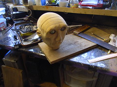
 I wanted a nice wooden base for the lamp. Conveniently I had a number of 3/4" oak planks, retrieved from a skip outside a fireplace shop (thanks, guys - they have been upcycled!) I measured out the head and cut three rectangular boards of about 6.5" x 5 3/4" (16.5cm x 14.5cm).
 The base needed to be a hollow box to house and hide the Arduino circuit and also act as a plinth for the head, and mount the controls.
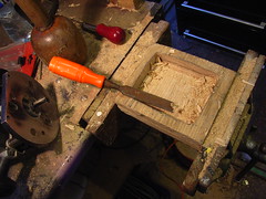
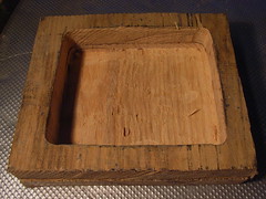 To build the box, two of the blanks would be joined and be hollowed out to form the box itself, with the other plank acting as the lid.
To create the hollow, a square hole was cut out of one of the planks. This was then glued to another plank. The hole in the top plank was then used as a router guide, to deepen the recess into the lower plank. This was then tidied up by hand with a good old fashioned bit of paring with a chisel

 On the left is the completed box. This was then sanded true using a power planer and then a large belt sander until it was a properly square-cornered, cuboid box. Finally it was finished off with an orbital sander using reducing grades of grit. (right)
Not shown in these photos are two locating pins that were set into the base of the box, and which fitted corresponding holes in the lid. These were used to keep the two halves lined up whilst sanding it with the lid on.
 Later (see next step) the control potentiometers were set into the box, and matching wooden knobs made for these. These were turned using a normal electric drill as a lathe, by holding it in a vice.
The knobs were turned from sections of the plank that had been roughly rounded off at one end with a rasp so the would fit in the drill chuck. This worked OK as the oak wood being used was hard enough not to snap with a spindle of only about 1/2".
To turn the knobs, a reducing coarseness of tools were applied to rough down then smooth off the knobs. These included wood rasps, Abra planes, fine metal files and eventually different grades of sandpaper on wood blocks.

 The knobs were cut off the spindle using a hacksaw, then a hole drilled into them to take the potentiometer spindle.
 Here are the three finished knobs, prior to fitting. (right)

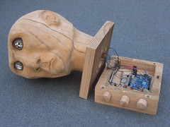 On the left is the finished head after it had been screwed onto the lid.
On the right the open box can be seen with the Arduino circuit in place. On the far right in this photo, one of the locating pins can be seen, that keeps the lid aligned when the lid is on.
The head is held on with brass wood screws. The control wires are routed through a hole cut in the lid)
Transferring the Circuitry From the Arduino Test-bed to the Final In-situ Wiring


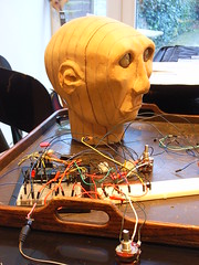
 Whilst perfecting the circuit and the controlling sketch on the test bed, the wiring was all connected up using breadboards and convenient pin-ended patch cables.
This was a varying mess of cables, and occasionally defunct parts of the earlier versions of the circuit were still left in the breadboard.
For example LEDs were used to visually indicate when a potentiometer had been moved in one version, but this was for testing only so did not need to be transferred to the final housing
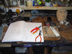
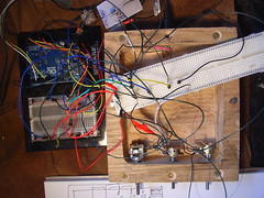 The first thing to do was to try to work out how the cables might fit in the box housing.
The final potentiometers were put in first, and then the circuit tested with these in place, with the rest of the circuit still on the breadboard. This was to check that the potentiometers and their connections had not been damaged during installation .

 A schematic wiring drawing was made to indicate where the wires would best fit into the box.
 This was a reference guide to to follow during the physical installation which made it pretty easy.
The potentiometers went in first (above, left) , followed by the Arduino board, and the additional transistor circuit (above, right)

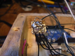 Most of the circuit components needed to be connected up between the earth and 5V power rails. This included the power/earth connections to the Arduino, the control potentiometers, the 2 servos and the LED/transistor circuit.
This was done by simply soldering all the power connections together a small offcut of circuit board (right) and all the earth connections on another (left)

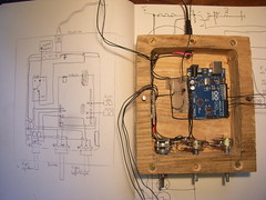 The wiring for the housing was all done using 1mm garden trellis wire. This can be bought at a garden shop and is much cheaper than buying from an electronics supplier.
It has the additional advantage of retaining it's shape when bent. This is because it has a single wire core, not a stranded core like most electronics wire.
This makes it great for staying neat in the box and doesn't require cable ties as it is quite rigid.
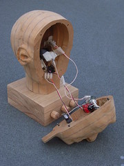 The ends of the connections were then connected via the conduit hole in the base of the head to a connection block to allow easy connection to the face control mechanism later.
 On the left is the finished head with the box open to expose the Arduino circuitry in the base.
On the right is the finished head with the face removed to show the flexible connections from the face mechanisms to the connection block in the base of the head.
Making the Power Supply for the Head

Most of this step is not really about Arduino. It's about transforming a dull old standard 5V power supply into a lovely oak one that matched the overall wooden vibe of the lamp.
Casing the power supply in wood

 The power supply was measured up and two thick oak planks cut for the casing,as close as possible to the size of the plug, because most electrical sockets have switches that stick out.
Any casing would need to be compact enough to not catch on such protusions. Using a hard wood like oak helped here as it is pretty strong even when thin.
A recess was cut out of both planks until the two halves fitted together. At the mains end of the power supply a hole was cut to allow the pins to pass through.

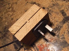 To keep the two halves lined up consistently, location pins were set into the casing (left).
This was mainly because to form the casing, they needed to be planed and sanded together to form a single block.
NOTE - a previous version was sanded with the power unit inside, and it did not work afterwards, presumably due to vibration damage!
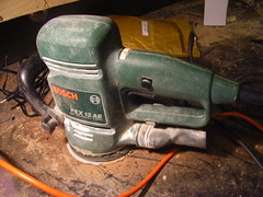
 An orbital sander was used to smooth down the block to a lovely fine finish.
Once done, the casing was glued round the power unit using PVA wood glue.
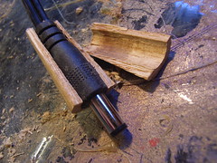
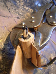 At the other end of the power lead, a conical casing was turned from oak for the small 5V plug. It was drilled out, then split into two halves.
The plug was set in, and the halves glued back together. A pair of self-locking mole grips were used as a vice. Thick paper was used to protect the wood from the teeth of the grips.
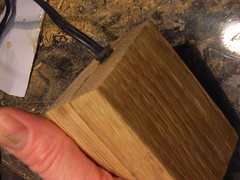
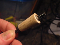
Here are the finished plugs.
Of course, you can't have wooden plugs with a plastic lead, so that had to be made wooden too.
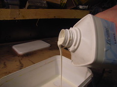
 To make the flexible lead wooden, it needed a flexible coating. I did consider threading it through long, hollow sections of wood like beads, but this seemed a bit clunky and quite hard to achieve.
Instead it was coated in fine sawdust, using liquid natural latex.
Latex is cheap and easy to get hold of from sculpture suppliers (and some flooring suppliers as it is used in self-levelling floors.)
Latex will dry overnight, or you can use accelerators. You can also apply heat with a hair drier to speed the setting process up. This is cheap and easy!
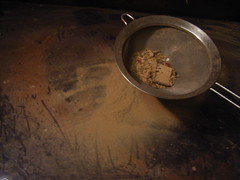
The sawdust is MDF sawdust from the sanding of the head. This is very fine, and also soft, not gritty, but to make sure it was really fine and free of other offcuts and woodchips it was sieved (right)
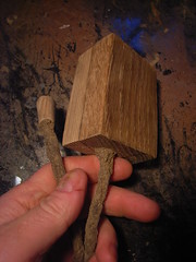
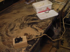 The coating was applied in several layers to build up strength. the final thickness was about 2mm all round the cable.
The finished cable resembled a root, which was rather appropriate given that is supplies the energy to the lamp.
Not all 5V power supplies are the same
During the attempt to make the wooden lead, I rather carelessly destroyed 2 units before eventually getting the final power unit made. The first I burnt out with some rough soldering, and a second suffered internal damage from the vibrations of a sander.
One issue this raised was that although i could easily find another 5V power supply, several of the ones I found wouldn't work properly. Both the lamps and the servos faltered under load. This turned out to simply be that they did not have a high enough power rating. Most could only supply 500mA current. When I used a unit of that rating, the circuit didn't work
The issues was that this project was using power 3W LEDs which draw a lot of current (potentially 0.6A each if operating at full power). The servos will also draw some current, (although this was harder to judge as the microservo didn't come with a datasheet listing the input power rating.)
The moral of this story was check your supply power can cope with your circuit's current demands! This would be even more important with heavy duty servos,
Casing the power supply in wood

 The power supply was measured up and two thick oak planks cut for the casing,as close as possible to the size of the plug, because most electrical sockets have switches that stick out.
Any casing would need to be compact enough to not catch on such protusions. Using a hard wood like oak helped here as it is pretty strong even when thin.
A recess was cut out of both planks until the two halves fitted together. At the mains end of the power supply a hole was cut to allow the pins to pass through.

 To keep the two halves lined up consistently, location pins were set into the casing (left).
This was mainly because to form the casing, they needed to be planed and sanded together to form a single block.
NOTE - a previous version was sanded with the power unit inside, and it did not work afterwards, presumably due to vibration damage!

 An orbital sander was used to smooth down the block to a lovely fine finish.
Once done, the casing was glued round the power unit using PVA wood glue.

 At the other end of the power lead, a conical casing was turned from oak for the small 5V plug. It was drilled out, then split into two halves.
The plug was set in, and the halves glued back together. A pair of self-locking mole grips were used as a vice. Thick paper was used to protect the wood from the teeth of the grips.


Here are the finished plugs.
Of course, you can't have wooden plugs with a plastic lead, so that had to be made wooden too.

 To make the flexible lead wooden, it needed a flexible coating. I did consider threading it through long, hollow sections of wood like beads, but this seemed a bit clunky and quite hard to achieve.
Instead it was coated in fine sawdust, using liquid natural latex.
Latex is cheap and easy to get hold of from sculpture suppliers (and some flooring suppliers as it is used in self-levelling floors.)
Latex will dry overnight, or you can use accelerators. You can also apply heat with a hair drier to speed the setting process up. This is cheap and easy!
The sawdust is MDF sawdust from the sanding of the head. This is very fine, and also soft, not gritty, but to make sure it was really fine and free of other offcuts and woodchips it was sieved (right)

 The coating was applied in several layers to build up strength. the final thickness was about 2mm all round the cable.
The finished cable resembled a root, which was rather appropriate given that is supplies the energy to the lamp.
Not all 5V power supplies are the same
During the attempt to make the wooden lead, I rather carelessly destroyed 2 units before eventually getting the final power unit made. The first I burnt out with some rough soldering, and a second suffered internal damage from the vibrations of a sander.
One issue this raised was that although i could easily find another 5V power supply, several of the ones I found wouldn't work properly. Both the lamps and the servos faltered under load. This turned out to simply be that they did not have a high enough power rating. Most could only supply 500mA current. When I used a unit of that rating, the circuit didn't work
The issues was that this project was using power 3W LEDs which draw a lot of current (potentially 0.6A each if operating at full power). The servos will also draw some current, (although this was harder to judge as the microservo didn't come with a datasheet listing the input power rating.)
The moral of this story was check your supply power can cope with your circuit's current demands! This would be even more important with heavy duty servos,