Arduino Controlled Bluetooth-bot
by johndavid400 in Circuits > Arduino
196766 Views, 333 Favorites, 0 Comments
Arduino Controlled Bluetooth-bot
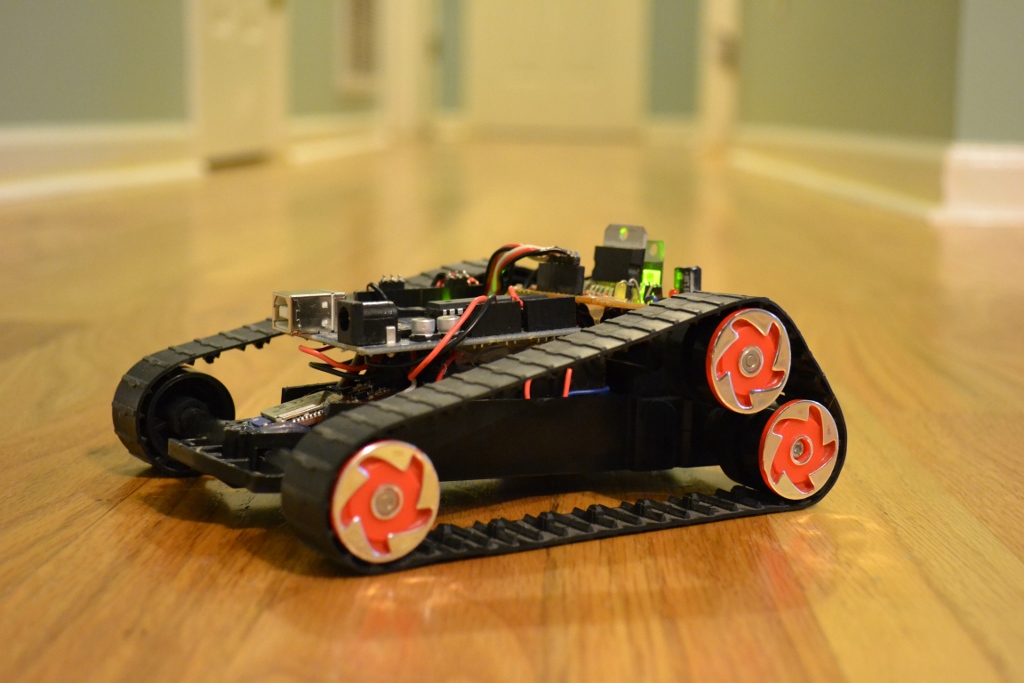
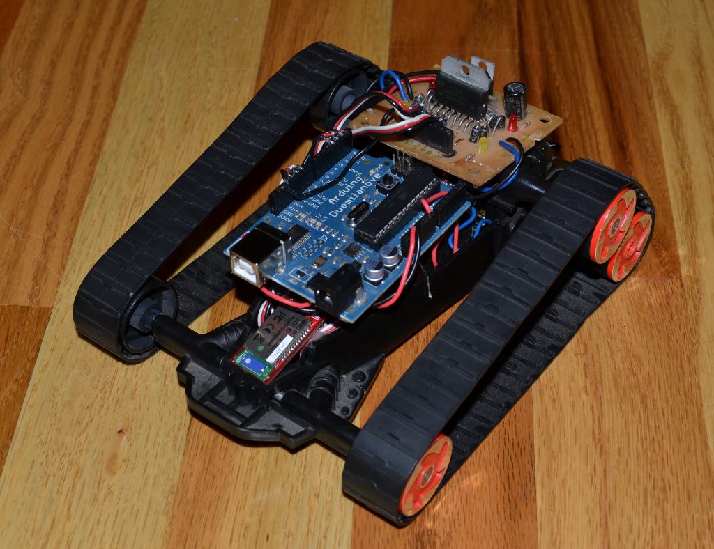
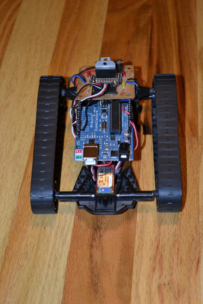
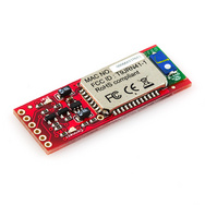
This instructable will show you how to convert an old toy R/C car from the thrift-store ($1.50) into a bluetooth controlled robot. To make the conversion, you will need an Arduino (any type), an L298N dual 2-amp motor-controller (or similar), and a bluetooth serial adapter from Sparkfun.com.
We will first remove all existing circuitry from the old toy and prepare it for its new brains. Then we will install the Arduino, motor-controller, and bluetooth adapter onto the top of the frame and wire everything up. Lastly, there are a few steps to complete on your computer to pair it with the bluetooth adapter on the robot. The building process is simple and straightforward, using hot-glue to secure each circuit board - which is easily removable later if desired.
To control this bot, I have assigned several keys on the keyboard to carry out various movements from the robot’s motors. By opening a terminal after pairing the Bluetooth-bot to your computer, you can send serial commands by pressing the “i” (forward), “j” (left), “k” (reverse), and “l” (right) keys to command the bot in any direction.
Here is a short video of the bluetooth-bot in action:
All parts can be purchased at Sparkfun.com, and the motor-controller can either be purchased as a shield (Ardu-moto shield), or built from scratch using the provided PCB layout files. You can download any of the files needed for this project (code and PCB files) from here:
https://sites.google.com/site/arduinorobotics/arduino-robotics/free_project
Tools needed:
Parts list:
This project was left over from my new book titled “Arduino Robotics” from Apress publishing. I decided to add it online for anyone to build. If you like this and want to see more Arduino based projects like it (including the Lawnbot400, ridable Seg-bot, GPS guided robo-boat, and many more), check out the book webpage:
Arduino Robtics
You can also check out some other projects that I have posted online at my website.
We will first remove all existing circuitry from the old toy and prepare it for its new brains. Then we will install the Arduino, motor-controller, and bluetooth adapter onto the top of the frame and wire everything up. Lastly, there are a few steps to complete on your computer to pair it with the bluetooth adapter on the robot. The building process is simple and straightforward, using hot-glue to secure each circuit board - which is easily removable later if desired.
To control this bot, I have assigned several keys on the keyboard to carry out various movements from the robot’s motors. By opening a terminal after pairing the Bluetooth-bot to your computer, you can send serial commands by pressing the “i” (forward), “j” (left), “k” (reverse), and “l” (right) keys to command the bot in any direction.
Here is a short video of the bluetooth-bot in action:
All parts can be purchased at Sparkfun.com, and the motor-controller can either be purchased as a shield (Ardu-moto shield), or built from scratch using the provided PCB layout files. You can download any of the files needed for this project (code and PCB files) from here:
https://sites.google.com/site/arduinorobotics/arduino-robotics/free_project
Tools needed:
- wire stripper/snips
- soldering iron
- small screwdriver
- hot-glue gun
Parts list:
- Arduino
- L298N motor-driver PCB or Ardumoto shield
- Bluetooth Mate Gold (or silver)
- wire
- old R/C toy with working motors (everything else will be scrapped)
This project was left over from my new book titled “Arduino Robotics” from Apress publishing. I decided to add it online for anyone to build. If you like this and want to see more Arduino based projects like it (including the Lawnbot400, ridable Seg-bot, GPS guided robo-boat, and many more), check out the book webpage:
Arduino Robtics
You can also check out some other projects that I have posted online at my website.
Toy Brain Surgery
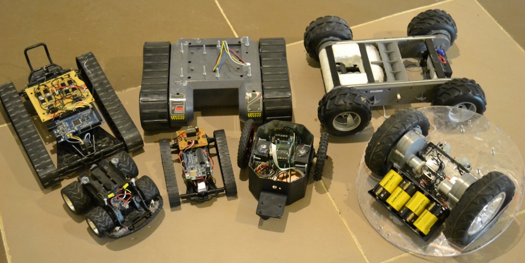
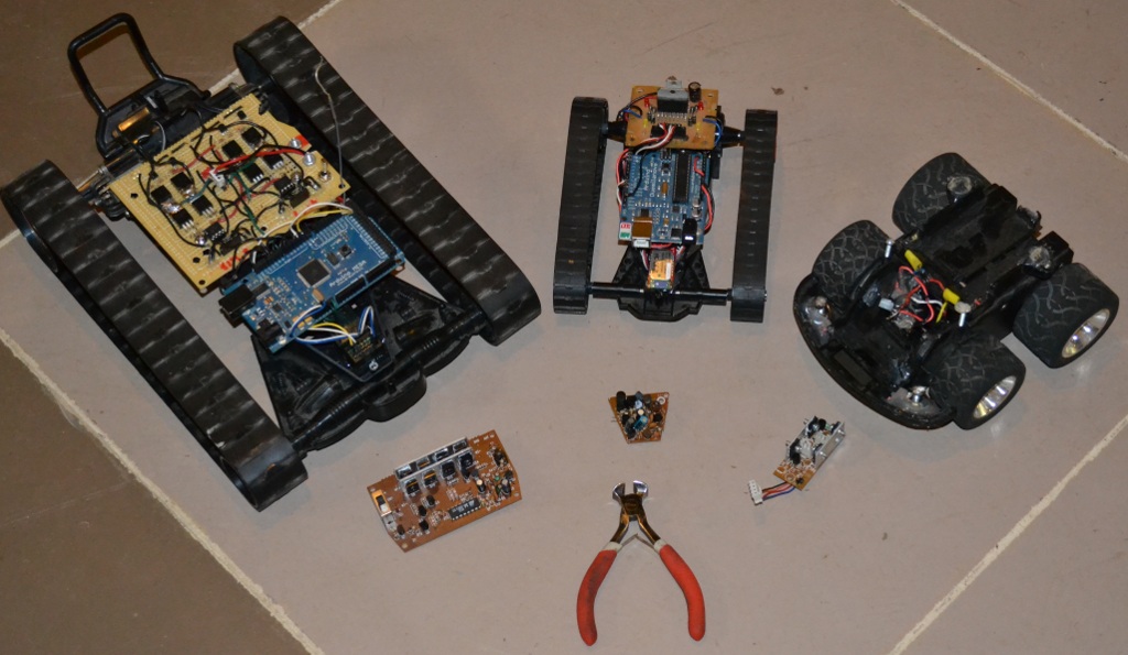
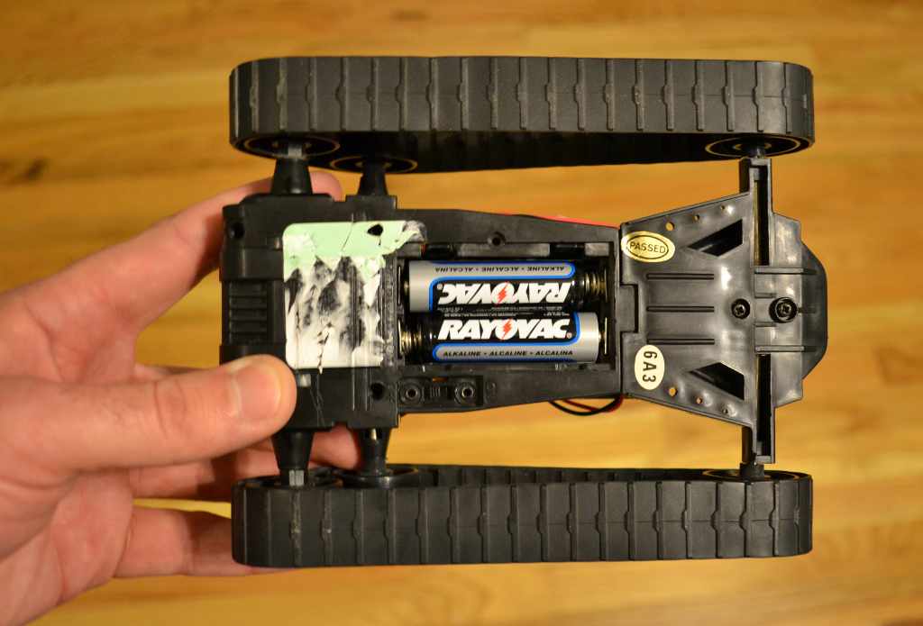
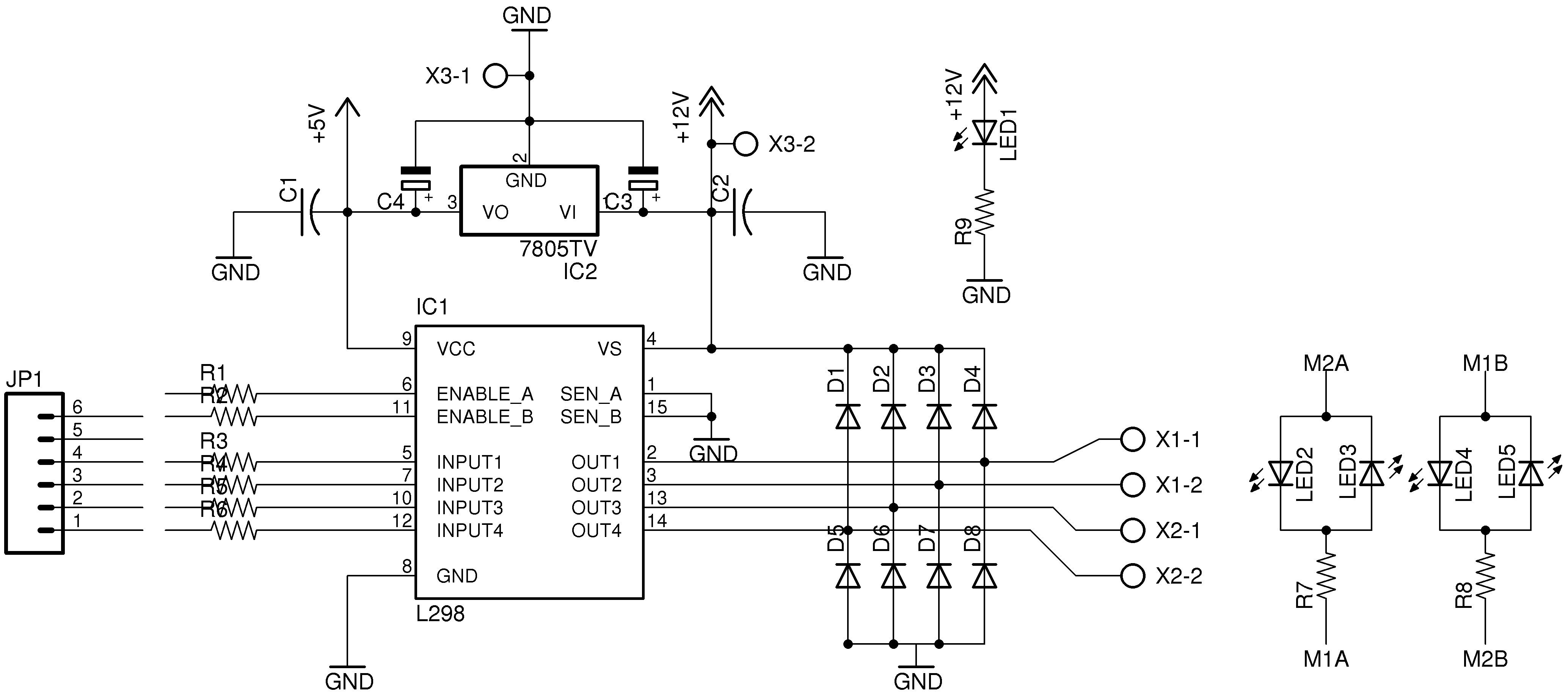
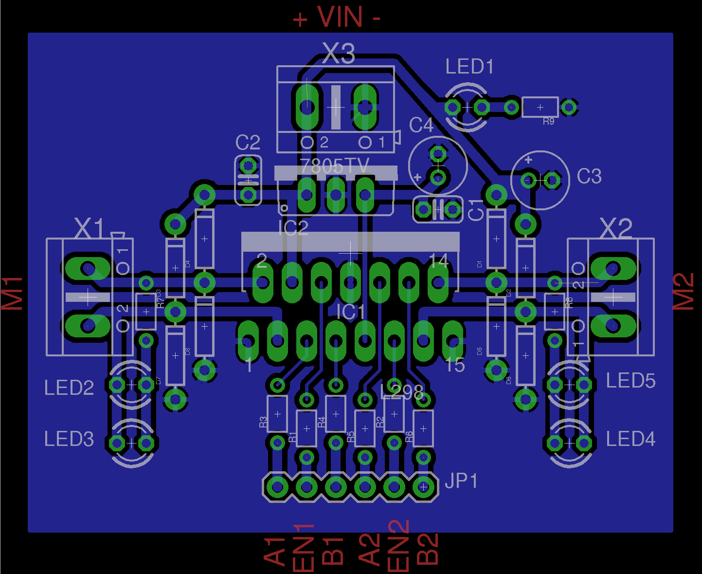
The PCB that came installed in the toy tank/car base had a small crystal for use with a AM radio transmitter and a few transistors to make a small H-bridge circuit for each motor. We will replace the old circuitry with an Arduino, a Bluetooth serial adapter, and an L298n dual motor-controller IC. The Arduino is reprogrammable, so you can obtain a variety of different behaviors with your bot, though I have only set up basic movement commands (fwd, rev, left, right).
First, strip the R/C car you got from the thrift-store, of all its electronic guts. This includes the motor-controller, R/C crystal, and any other PCB's installed. We will only need two wires to each motor and a set of wires to the battery compartment. The code for this project is intended for use with a "tank-steer" type robot, utilizing one motor on each side of the robot, like a tank. With bi-directional control of each motor, we can turn the robot in a circle without moving forward or reverse (called a "zero-turn radius"). This type of control is extremely effective, especially at slower speeds.
Note: You do not have to have find a toy vehicle with tank tracks, there are many R/C toys at the thrift-store that have wheels, but utilize tank steering - just make sure your vehicle has a drive motor installed on each side. I was able to find several "tracked" tank-steering vehicles at my local thrift-store, with regular visits and a few months time.
Once you remove the old electronic circuits from the toy, we will need a place to mount the Arduino board, the motor-controller PCB, and the small Bluetooth adapter (we will use the battery compartment built in to the toy). If you use an Ardumoto shield for the Arduino, you will only need a place to mount the Arduino. I used a hot-glue gun to add a small blob of glue to the top of the toy base - then mount the Arduino. Using low-temp glue will keep the Arduino securely attached, but also allow you to remove it later without damage if desired.
I designed a small PCB that uses an L298N dual motor driver IC to control (2) DC motors in either direction and with full speed control. The PCB files were created using the freeware version of Eagle CAD and can be used to build your own motor-controller. If you would not like to build your own PCB, you can buy the Ardumoto motor-controller from Sparkfun.com which uses a surface mount version of the same L298N IC (control pin reassignment may be required in the code).
Download the Eagle files for the L298N motor-controller and code for this project here:
https://sites.google.com/site/arduinorobotics/arduino-robotics/free_project
Wiring Connections
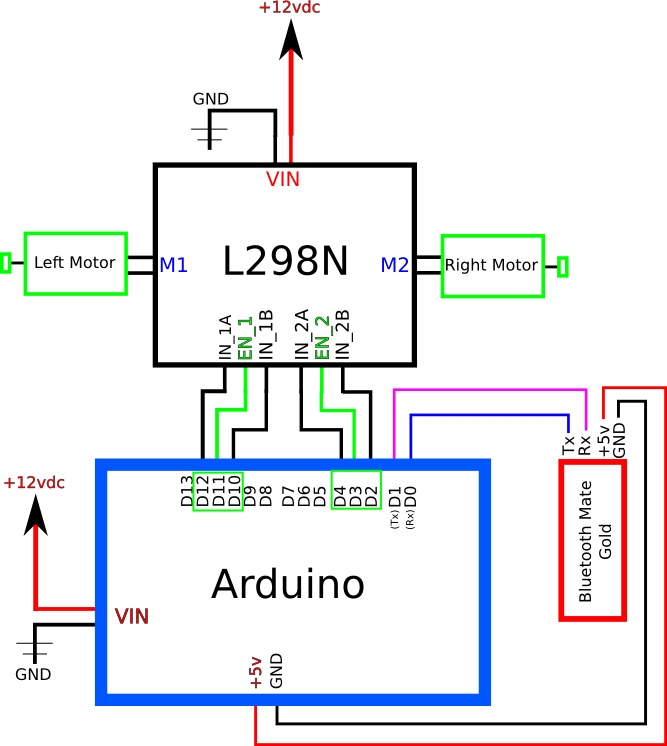
To get a robot running using Bluetooth, there are very few connections. (3) wires to control each motor from the Arduino to motor-controller, (2) wires for the Bluetooth serial adapter to Arduino, the (4) motor wires, and a few power wires. I used male-pin headers to make patch cables from the Arduino to the motor-controller PCB (both using female headers). If you are using the Sparkfun Ardumoto shield, you will not need to wire the motor controller to the Arduino, just the Bluetooth adapter and power.
The L298N motor driver IC uses 3 inputs for each motor (input A, input B and Enable) to determine both speed and direction. Speed control is most easily accomplished by setting the inputs A and B to determine the direction and using the Enable pin to apply the PWM speed control signal.
See the provided wiring diagram for specific connections.
Test (with Kitties)
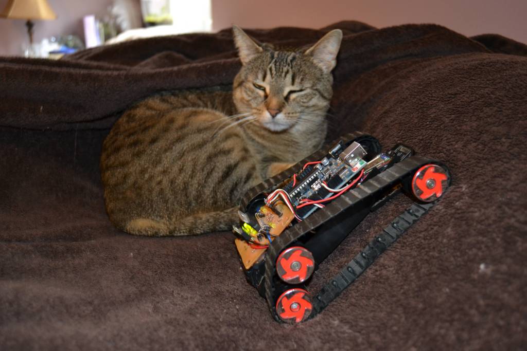
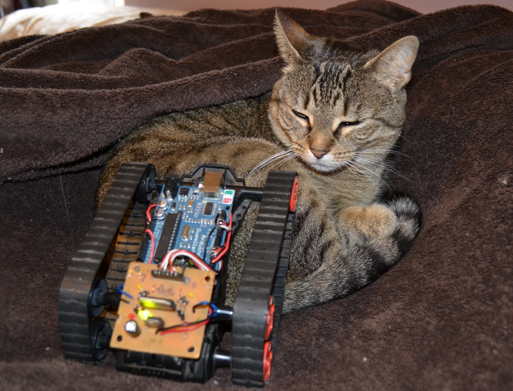
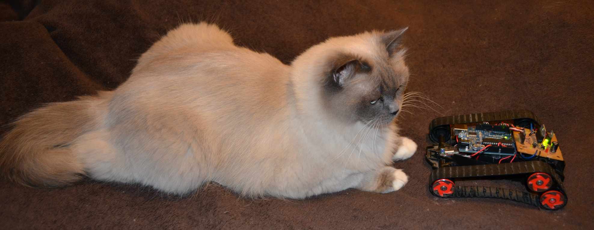
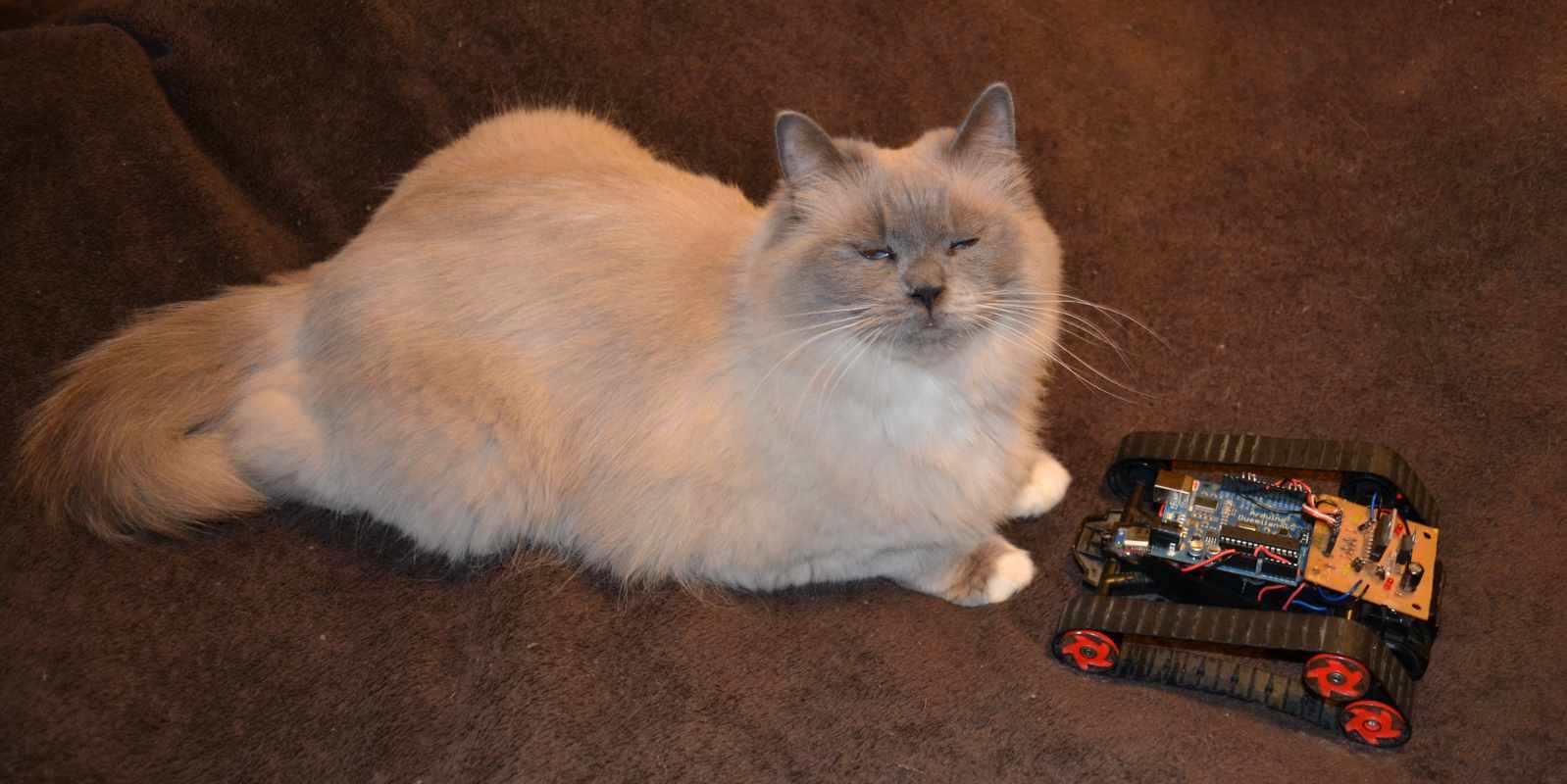
Once you have made the connections between the Bluetooth mate, Arduino, and L298N motor-controller, it is time to install the batteries into the battery compartment. and load the code to the Arduino.
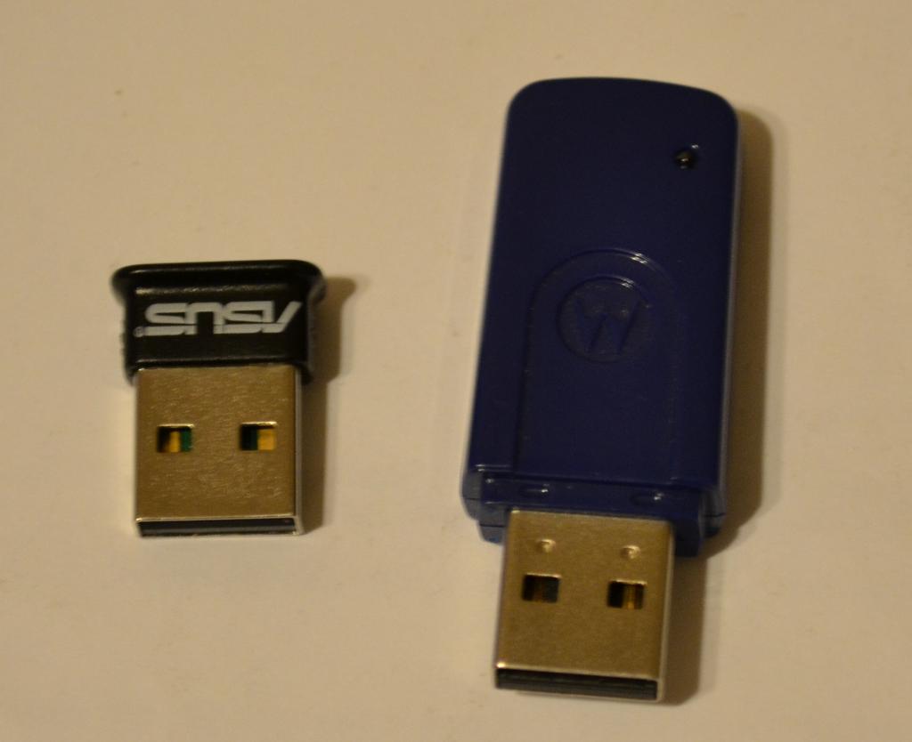
With the code loaded, you will need to "pair" the bluetooth adapter and Bluetooth Mate on your computer. The process to do this will be slightly different depending on what Operating System you are using. First plug in any standard bluetooth adapter
The following steps will describe how to pair your Bluetooth device using Ubuntu 10.10:
Step 1. Turn On Bluetooth-bot and make sure the power LED on the Bluetooth mate is On (blinking red).
Step 2. Open your bluetooth manager (System > Preferences > Bluetooth Manager) - if not installed, open terminal and type:
"sudo aptitude install blueman", and then continue.
Step 3. Click the Search button to discover new devices.
Step 4. Right click on the Bluetooth Mate from the list (mine was listed as "FireFly - A4C7") and select the option for "Serial port" - you might also see your cell phone show up on the list if available, make sure you select the correct device.
Step 5. Now you will see a dialog box asking for the passcode of the Bluetooth Mate - mine was set by default to "1234".
Step 6. With the passcode entered, your Bluetooth Mate should now be connected to your PC - the red blinking light on the Bluetooth mate will turn solid green to let you know that it is connected.
Step 7. To control the bot, open a terminal and type the following: "screen /dev/rfcomm0 115200"
The full instructional video on how to set up your Bluetooth-bot with your PC is here:
Now you should be controlling your robot using the keyboard. Make sure the Caps lock is turned Off and use the following keys (lower-case i, j, k, and l) to make your robot move. Holding a key down will result in constant movement, let go and the bot should stop:
forward = "i"
reverse = "k"
left = "j"
right = "l"
speed value UP = "."
speed value DOWN = ","
max speed = "/"
Additionally, you can change the speed value that is written to the motors by pressing the period, comma, and back-slash keys. The "comma" key is used to lower the speed value (from 0-255), the "period" key is used to raise the speed value (increments of 5), and the "back-slash" key is used to set the speed_value to 255 (max).
Any other key that is pressed on the computer keyboard with the terminal open, will yield a response (the LED will blink), but no motor action will be commanded. If you would like to assign different keys to the control functions, simply open the serial monitor (at 115,200 bps) and press the key you would like to use - the Arduino will display the BYTE value on the serial monitor of any key that is pressed, so you can record the value shown and modify the sketch accordingly.
Once you get your Bluetooth-bot working, feel free to add more movement functions and modify the code as you please - if you mess it up, just download the original code again. The code is also available on the next page for viewing.
Code

This code can be downloaded from the book website:
https://sites.google.com/site/arduinorobotics/arduino-robotics/free_project
// Bluetooth-bot v1
// Arduino Robotics unofficial chapter 14
// use Bluetooth Mate serial adapter to receive commands from PC
// Arduino decodes commands into motor movements
// Creates high-speed wireless serial link for robot control using keyboard
// Uses keys "i" = forward, "j" = left, "k" = reverse, and "l" = right
// speed control is also implemented using "," = speed down, "." = speed up, and "/" = max speed.
// L298 motor control variables
int M1_A = 12; // if using Ardumoto, change to pin 13
int M1_PWM = 11;
int M1_B = 10; // if using Ardumoto, remove this variable
int M2_A = 4; // if using Ardumoto, change to pin 12
int M2_PWM = 3;
int M2_B = 2; // if using Ardumoto, remove this variable
// LED pin attached to Arduino D13
int LED = 13;
// variable to store serial data
int incomingByte = 0;
// variable to store speed value
int speed_val = 255;
//////////////////////////////
void setup(){
TCCR2B = TCCR2B & 0b11111000 | 0x01; // change PWM frequency for pins 3 and 11 to 32kHz so there will be no motor whining
// Start serial monitor at 115,200 bps
Serial.begin(115200);
// declare outputs
pinMode(LED, OUTPUT);
pinMode(M1_A, OUTPUT);
pinMode(M1_PWM, OUTPUT);
pinMode(M1_B, OUTPUT);
pinMode(M2_A, OUTPUT);
pinMode(M2_PWM, OUTPUT);
pinMode(M2_B, OUTPUT);
// turn motors Off by default
M1_stop();
M2_stop();
delay(500);
}
////////////////////////////////////
void loop(){
// check for serial data
if (Serial.available() > 0) {
// read the incoming byte:
incomingByte = Serial.read();
// if available, blink LED and print serial data received.
digitalWrite(LED, HIGH);
// say what you got:
Serial.print("I received: ");
Serial.println(incomingByte);
// delay 10 milliseconds to allow serial update time
delay(10);
// check incoming byte for direction
// if byte is equal to "46" or "," - raise speed
if (incomingByte == 46){
speed_val = speed_val + 5;
test_speed();
Serial.println(speed_val);
}
// if byte is equal to "44" or "." - lower speed
else if (incomingByte == 44){
speed_val = speed_val - 5;
test_speed();
Serial.println(speed_val);
}
// if byte is equal to "47" or "/" - max speed
else if (incomingByte == 47){
speed_val = 255;
test_speed();
}
// if byte is equal to "105" or "i", go forward
else if (incomingByte == 105){
M1_forward(speed_val);
M2_forward(speed_val);
delay(25);
}
// if byte is equal to "106" or "j", go left
else if (incomingByte == 106){
M1_reverse(speed_val);
M2_forward(speed_val);
delay(25);
}
// if byte is equal to "108" or "l", go right
else if (incomingByte == 108){
M1_forward(speed_val);
M2_reverse(speed_val);
delay(25);
}
// if byte is equal to "107" or "k", go reverse
else if (incomingByte == 107){
M1_reverse(speed_val);
M2_reverse(speed_val);
delay(25);
}
// otherwise, stop both motors
else {
M1_stop();
M2_stop();
}
}
else {
M1_stop();
M2_stop();
digitalWrite(LED, LOW);
}
}
void test_speed(){
// constrain speed value to between 0-255
if (speed_val > 250){
speed_val = 255;
Serial.println(" MAX ");
}
if (speed_val < 0){
speed_val = 0;
Serial.println(" MIN ");
}
}
/////////// motor functions ////////////////
void M1_reverse(int x){
digitalWrite(M1_B, LOW);
digitalWrite(M1_A, HIGH);
analogWrite(M1_PWM, x);
}
void M1_forward(int x){
digitalWrite(M1_A, LOW);
digitalWrite(M1_B, HIGH);
analogWrite(M1_PWM, x);
}
void M1_stop(){
digitalWrite(M1_B, LOW);
digitalWrite(M1_A, LOW);
digitalWrite(M1_PWM, LOW);
}
void M2_forward(int y){
digitalWrite(M2_B, LOW);
digitalWrite(M2_A, HIGH);
analogWrite(M2_PWM, y);
}
void M2_reverse(int y){
digitalWrite(M2_A, LOW);
digitalWrite(M2_B, HIGH);
analogWrite(M2_PWM, y);
}
void M2_stop(){
digitalWrite(M2_B, LOW);
digitalWrite(M2_A, LOW);
digitalWrite(M2_PWM, LOW);
}