Radio-Control Car With 2 Speed Modes - AWD
by abdullahkhalid098 in Circuits > Arduino
2041 Views, 22 Favorites, 0 Comments
Radio-Control Car With 2 Speed Modes - AWD
.png)
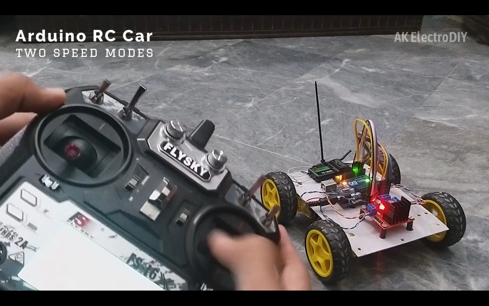
This project is about making an arduino-based RC Car. The unique thing for this car is, it uses a Hobby-Grade Transmitter and Receiver system which gives a proportional control and also it gives a very long range. As long as 1km!
Supplies
.png)
.png)
.png)
.png)
.png)
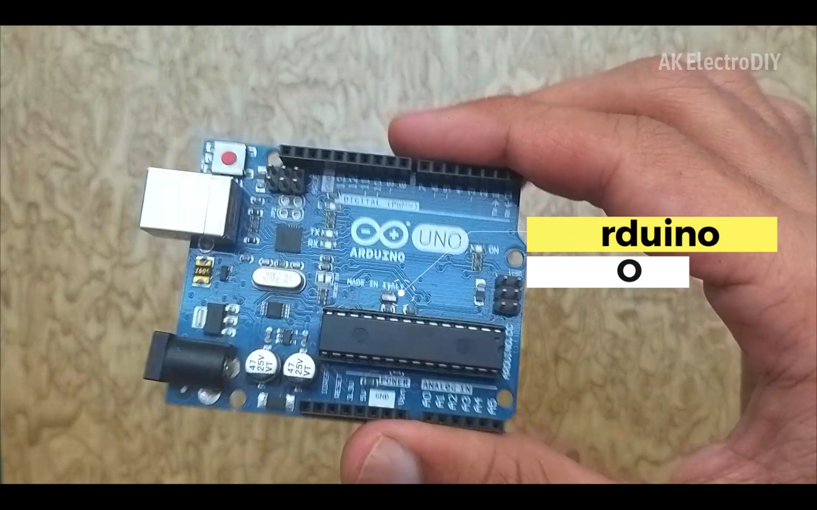
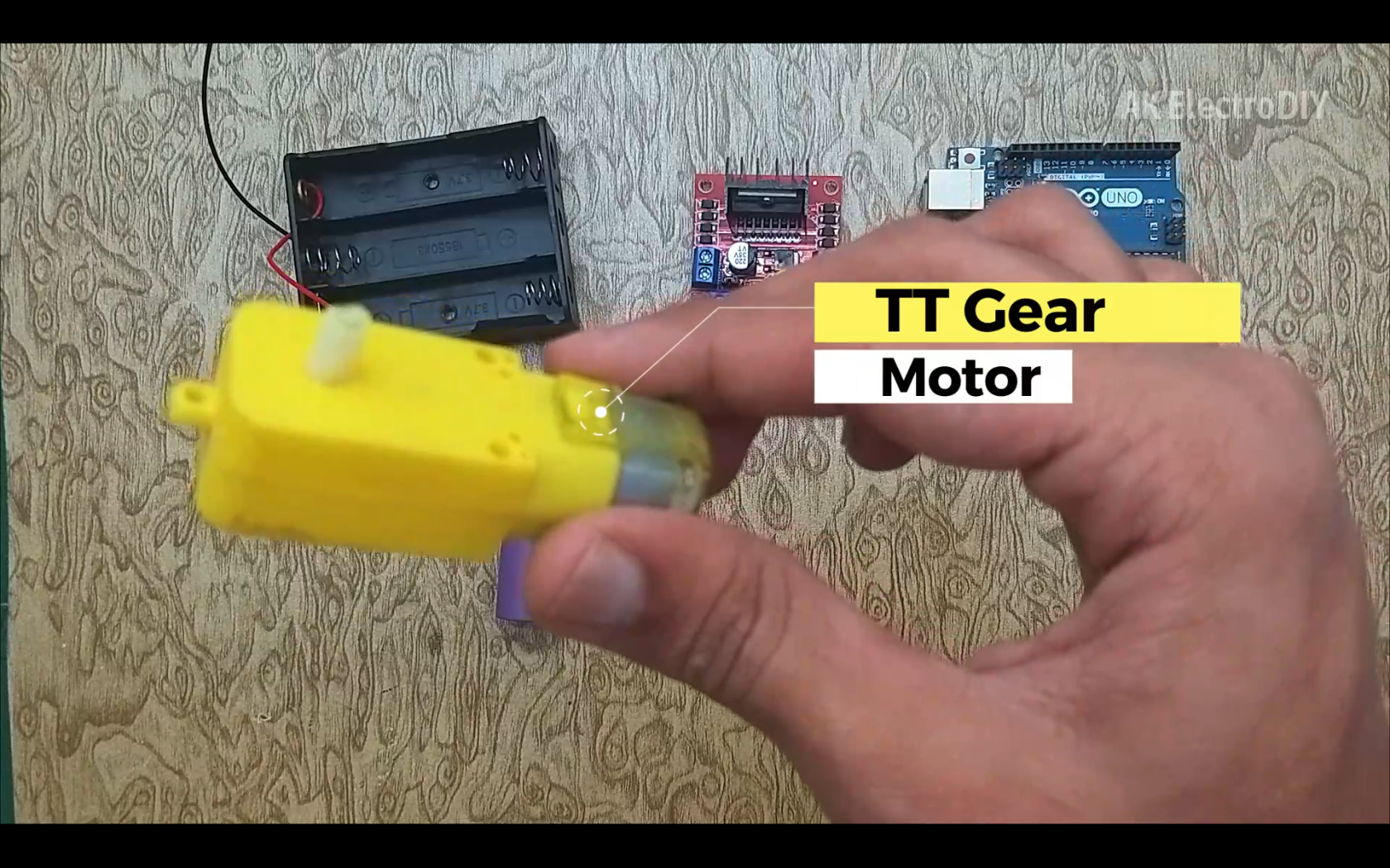
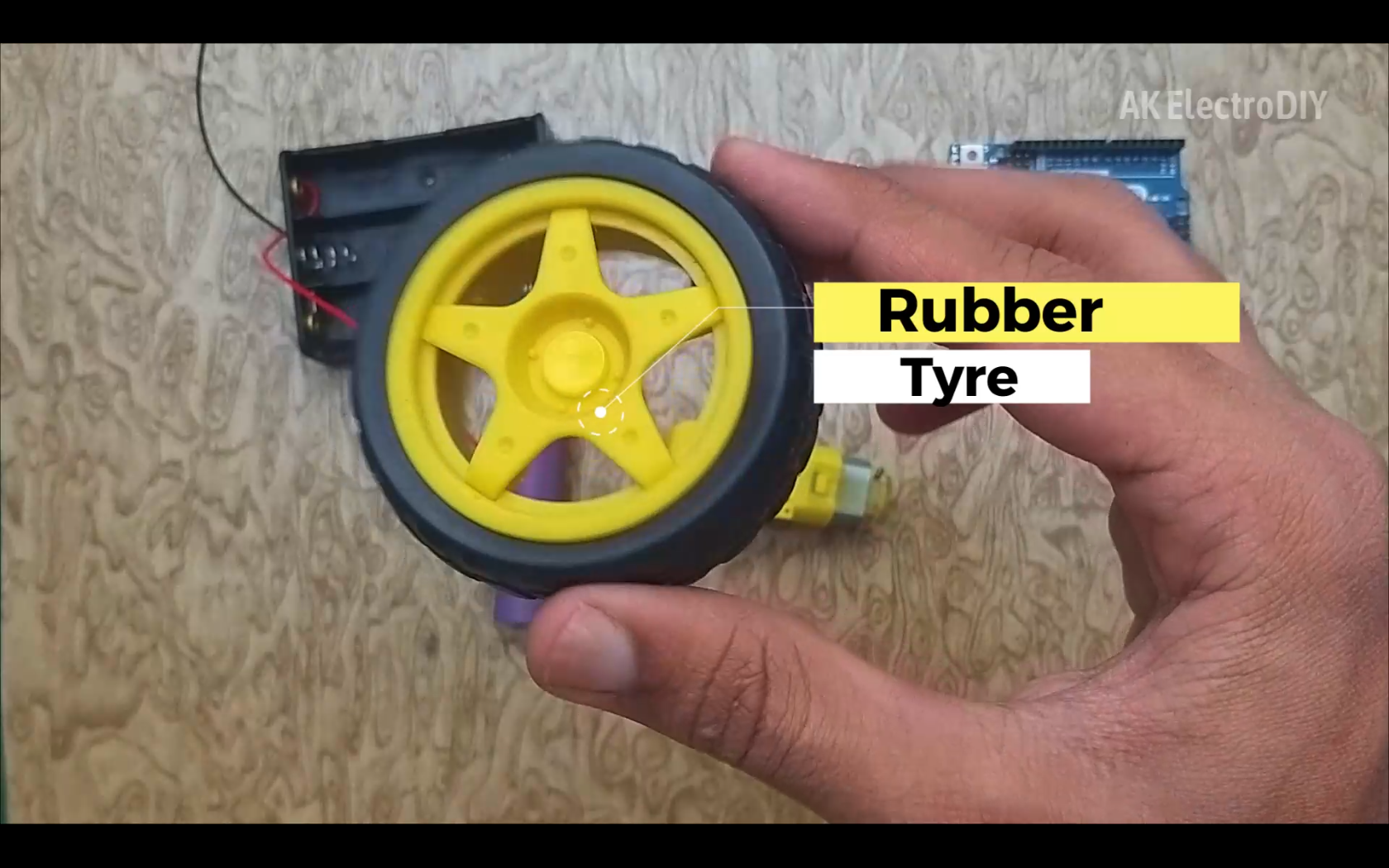
For this Project, we need:
- Arduino UNO
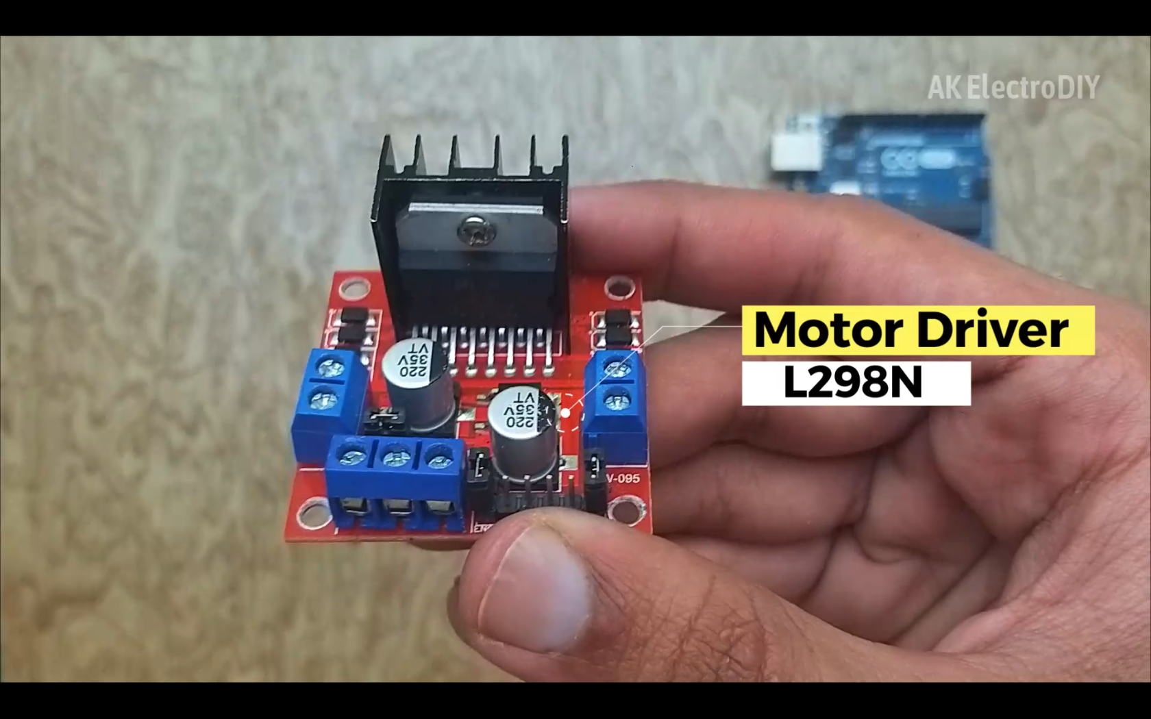
- L298N Motor Driver
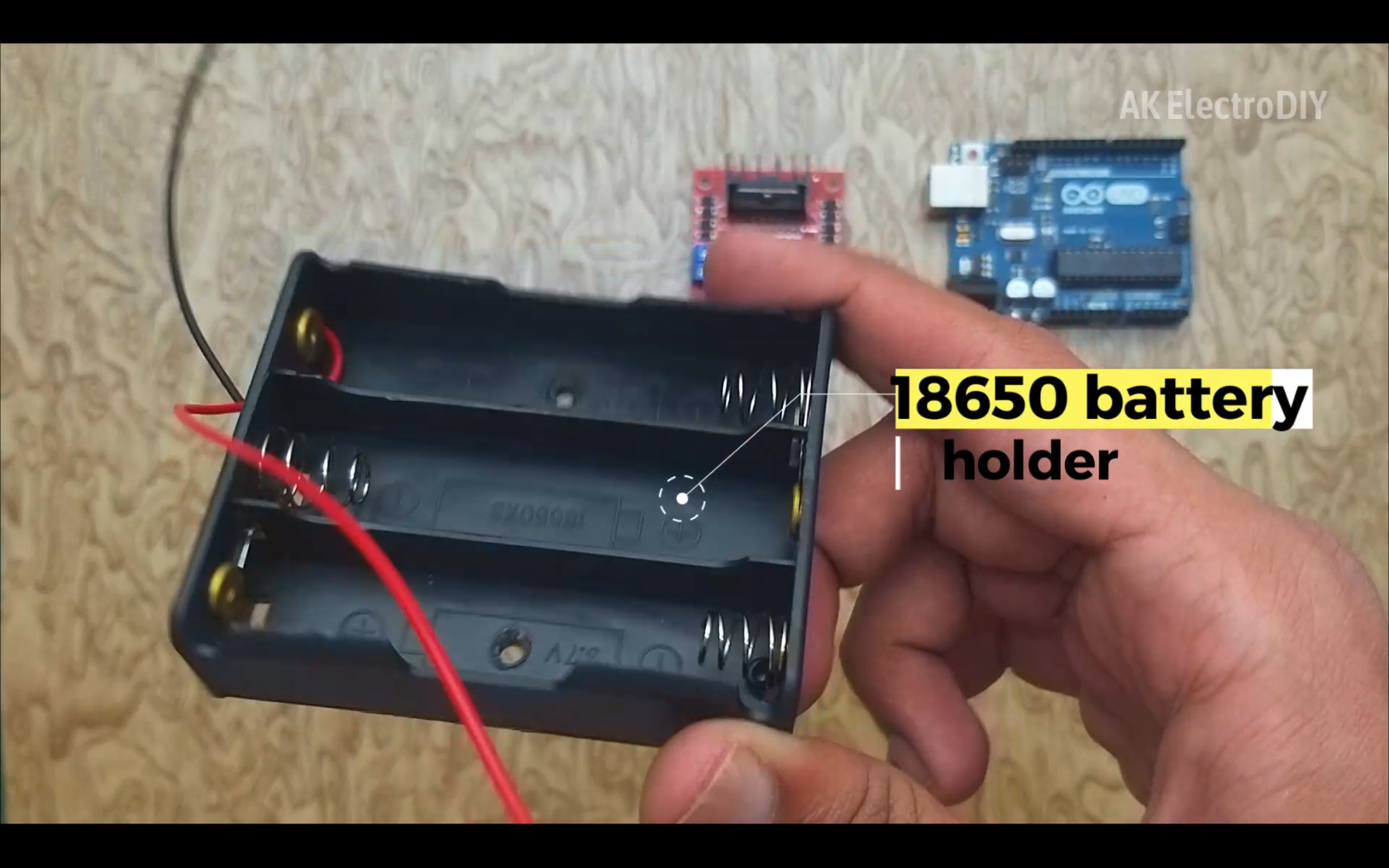
- 18650 battery
- 18650 battery holder
- TT Gear Motors
- Rubber Tyres
For the Radio Control System, I am using:
- Flysky i6X Transmitter
- Flysky iA6B Receiver
Circuit Diagram:
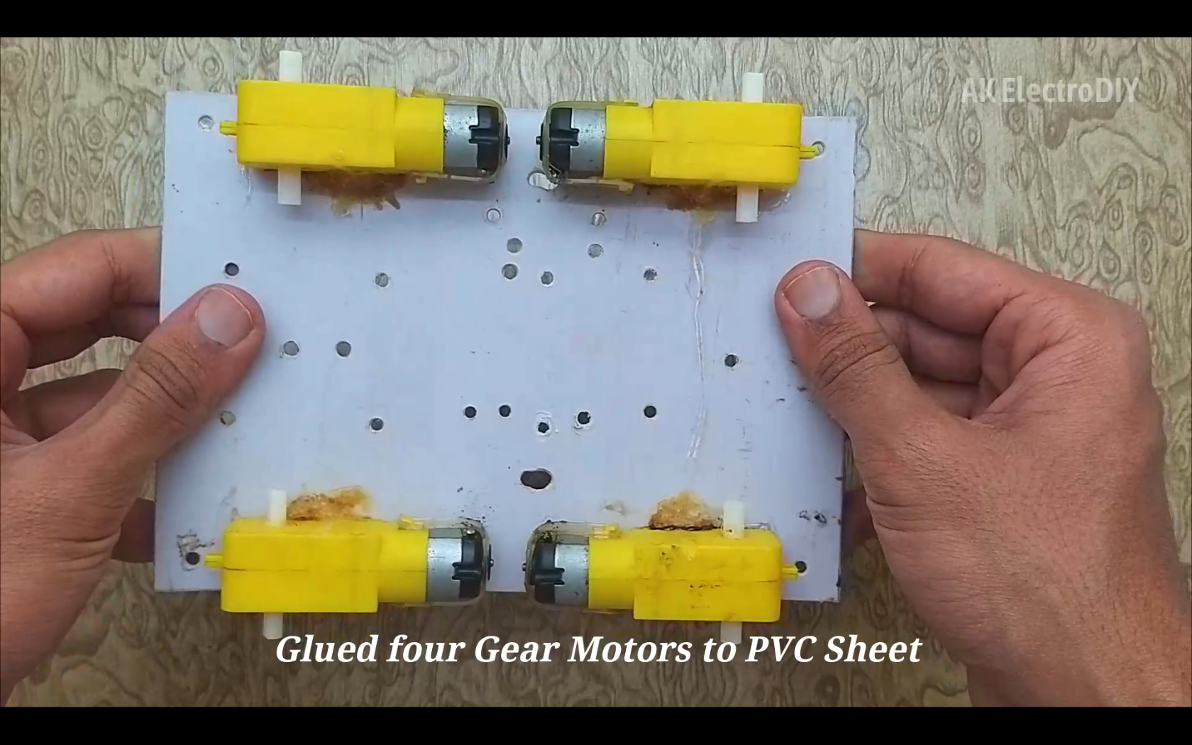
Installing Motors
.png)
The first step is to attach the motors to a base using hot glue.
Installing the Battery Holder
.png)
The 2nd step is to install the battery holder. You can install it at any place you want. But I had space at the under of the base, so I installed it there.
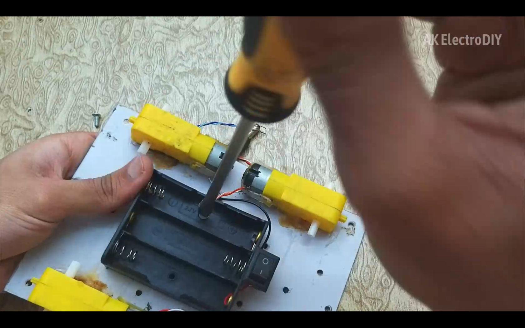
Installing Arduino and Motor Driver
.png)
.png)
.png)
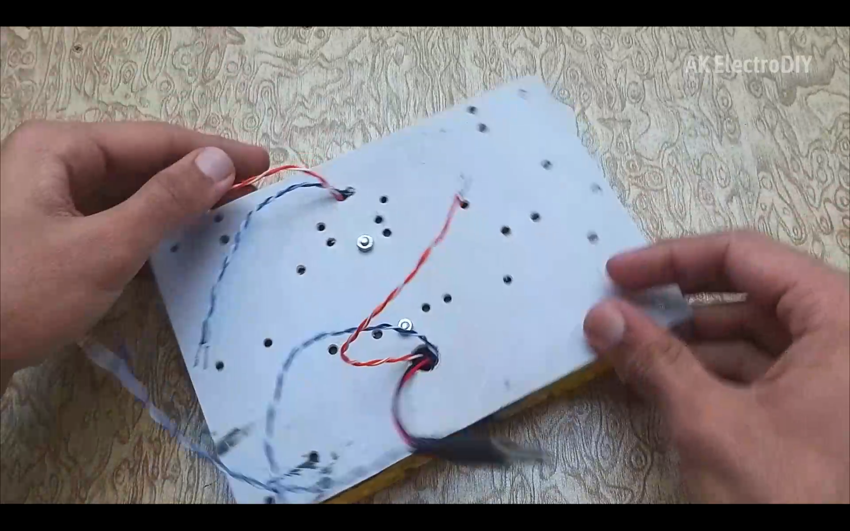
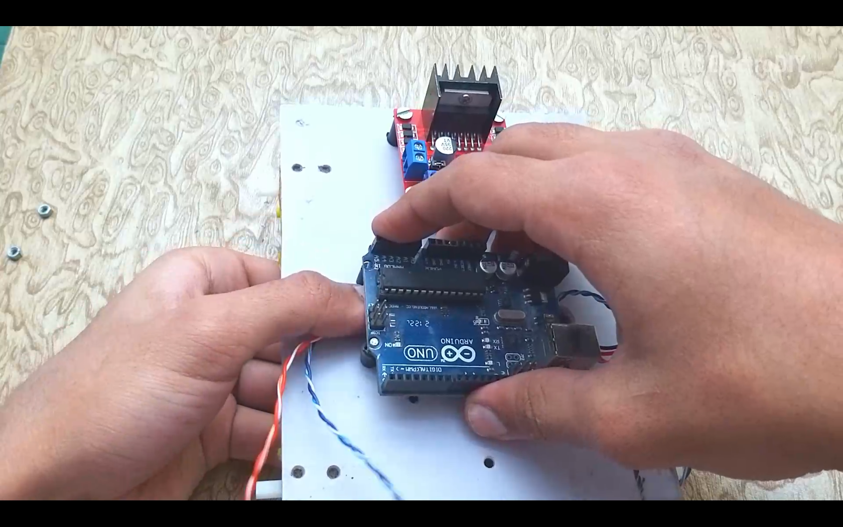
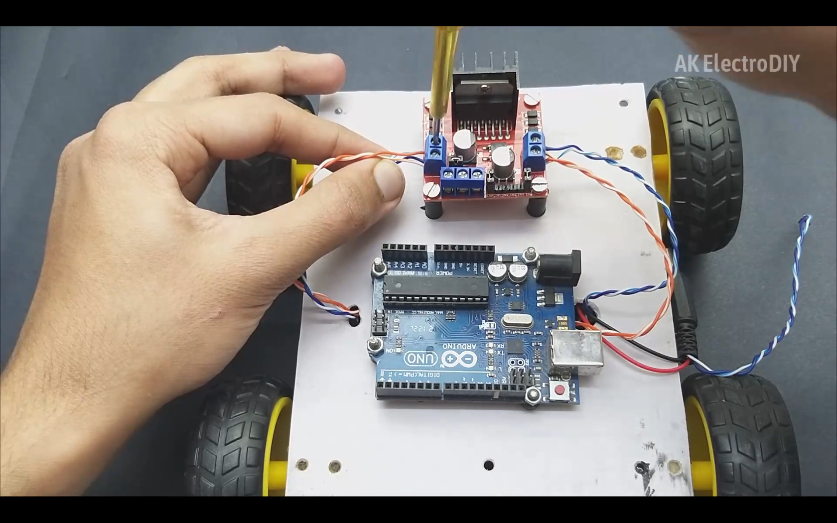
The wires of motors shall come out to the top part of the base. Next up, we install the Arduino and the L298N motor driver. For installing these components, I am using Nuts and Bolts. After installing these, we can connect the motor wires to the motor driver and fix them in place using a screw driver.
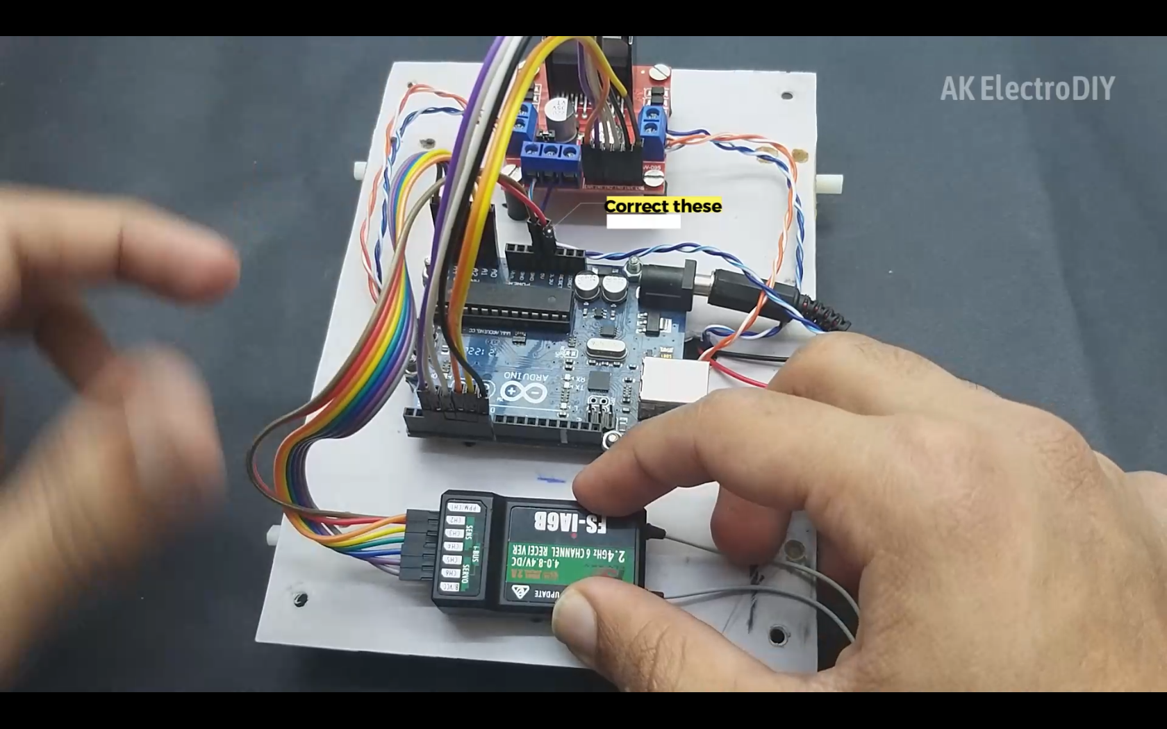
Installing the Receiver
.png)
.png)
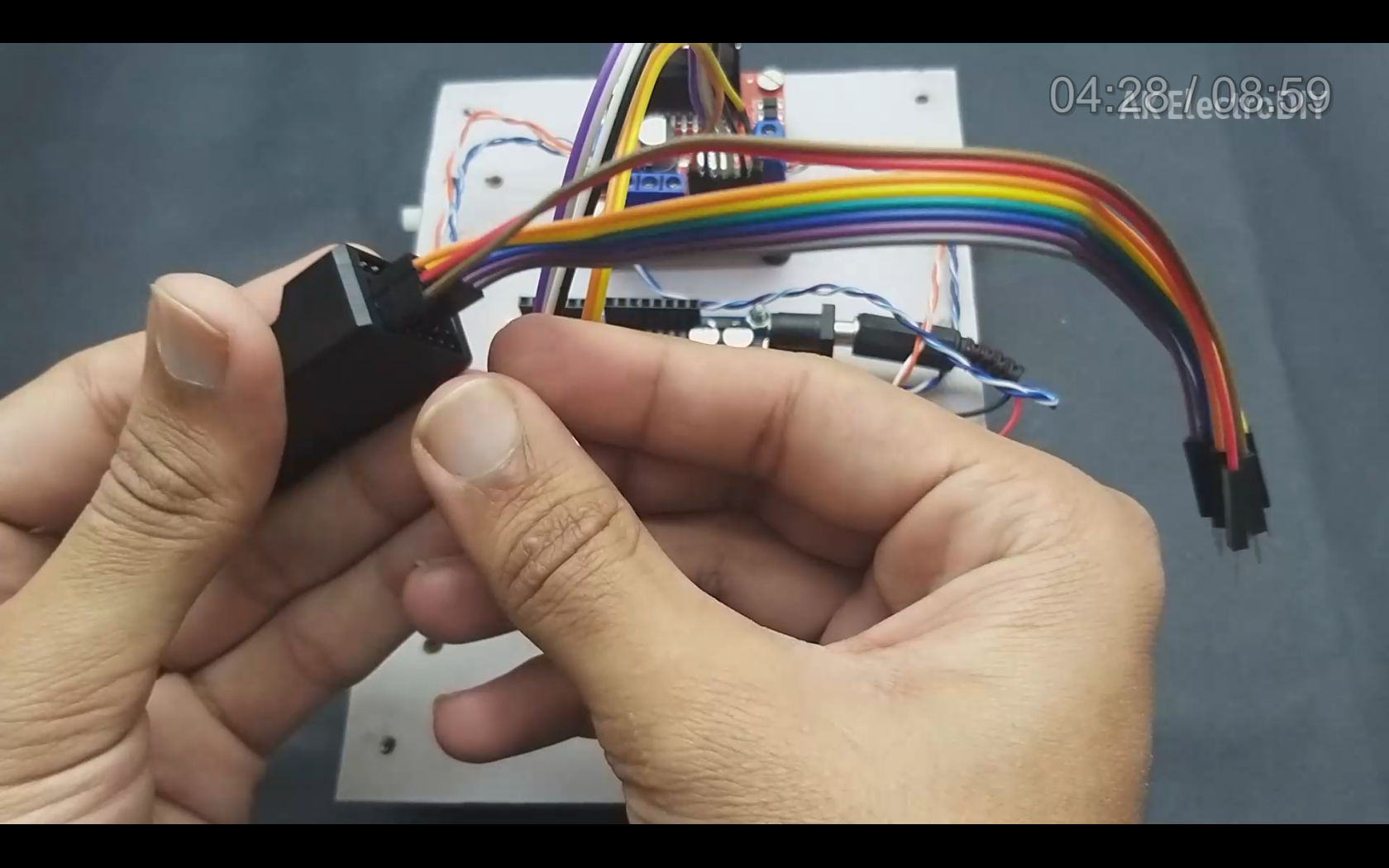
The next step is to install the receiver and connect its wires to arduino according to the circuit diagram mentioned above.
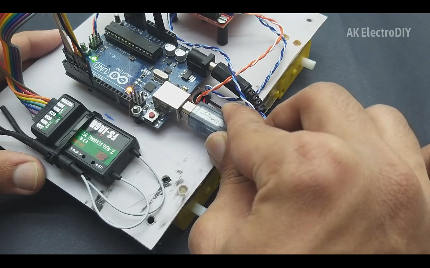
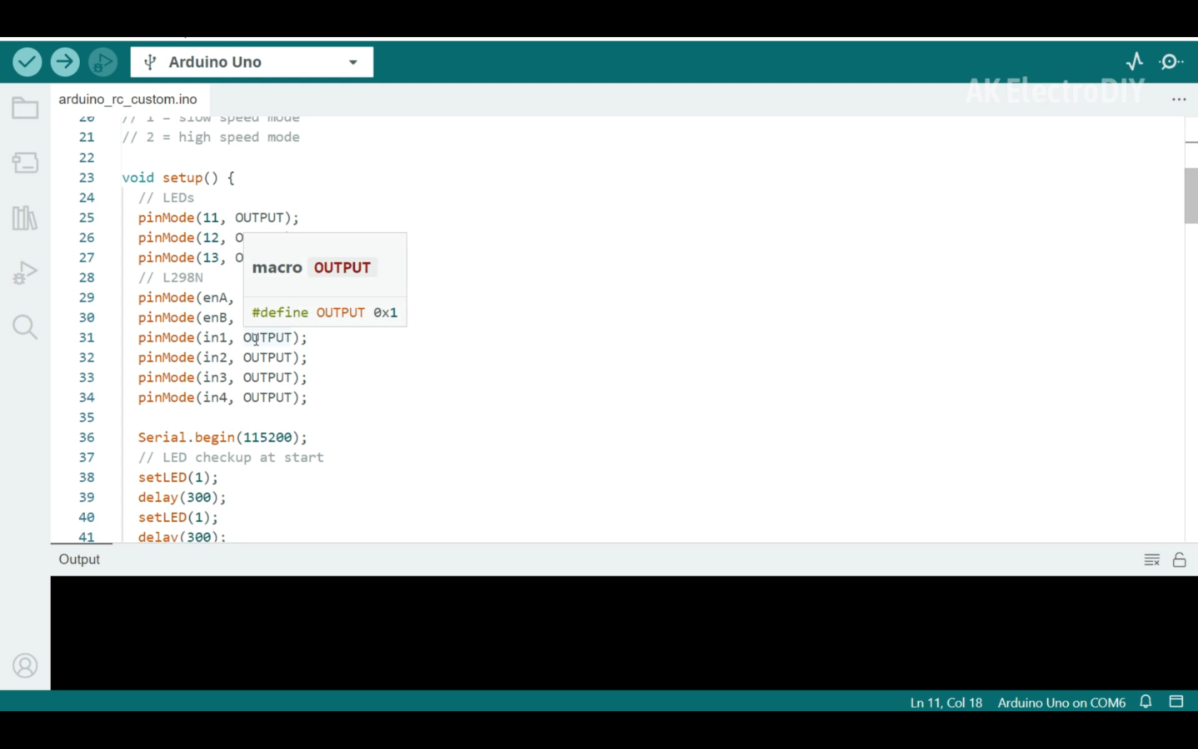
Programming
.png)
.png)
The hardware part is almost complete. Now we can program the robot. We connect the Arduino to our computer using a USB cable, and then upload the code. The code is given below.
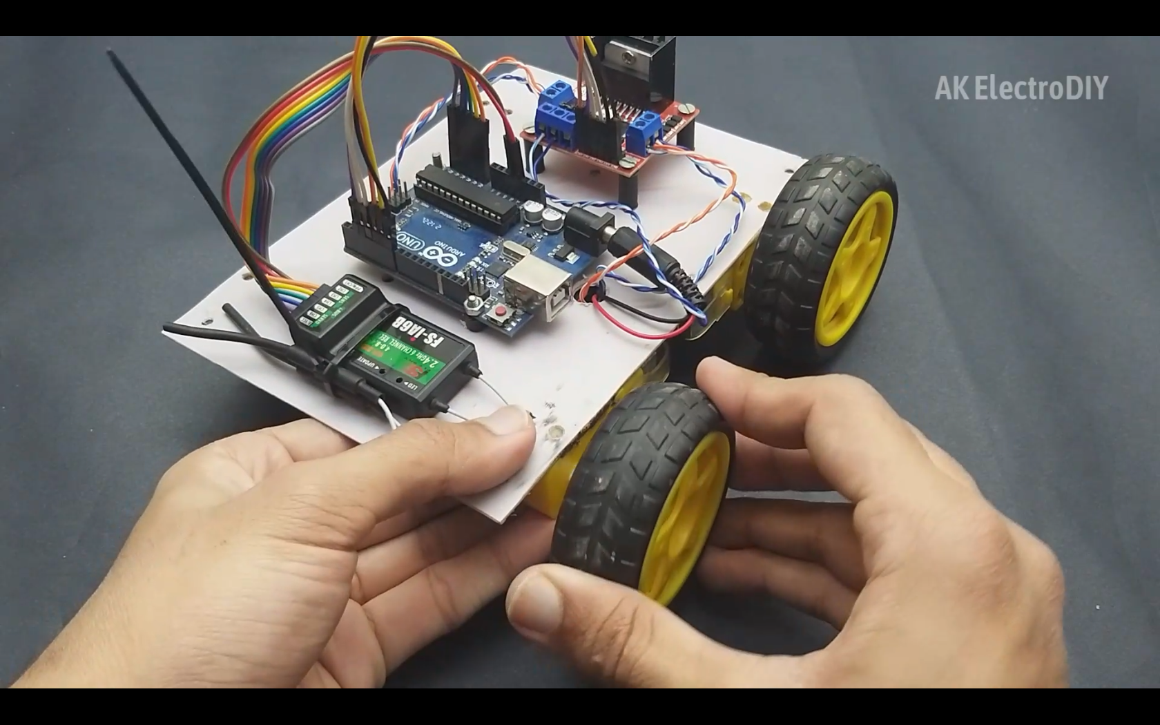
Installing Tyres and Inserting Batteries
.png)
.png)
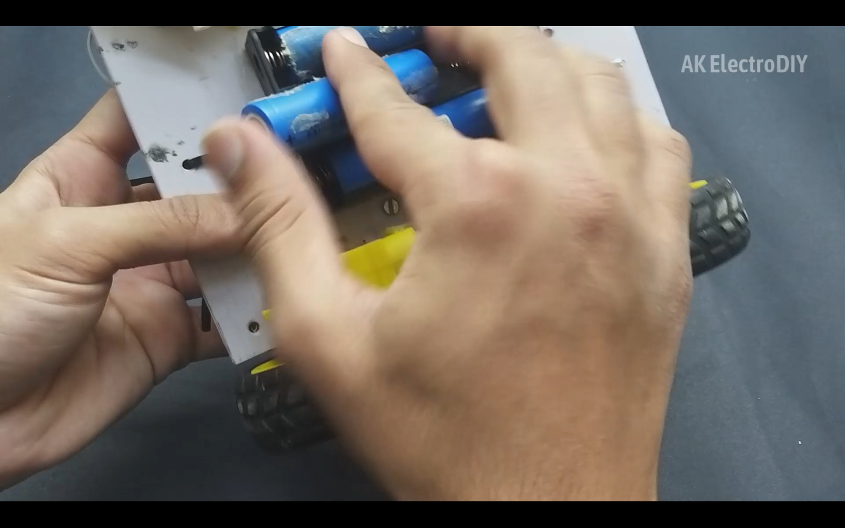
Now we can install the tyres and insert 3 18650 batteries.
Transmitter Setup
.png)
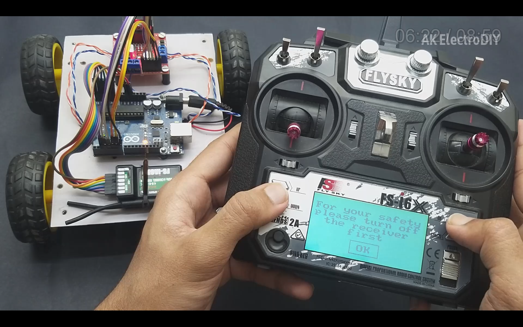
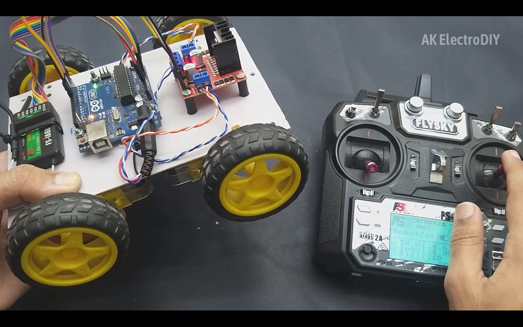
The final step is to set up the Transmitter.
It is very simple. We just need to set 2 aux switches to channels 5 and 6. We can use these switches to switch between modes. We have 1 switch to arm and disarm the motors. And 2nd switch to set the motor speeds.
Enjoy!
.png)
.png)
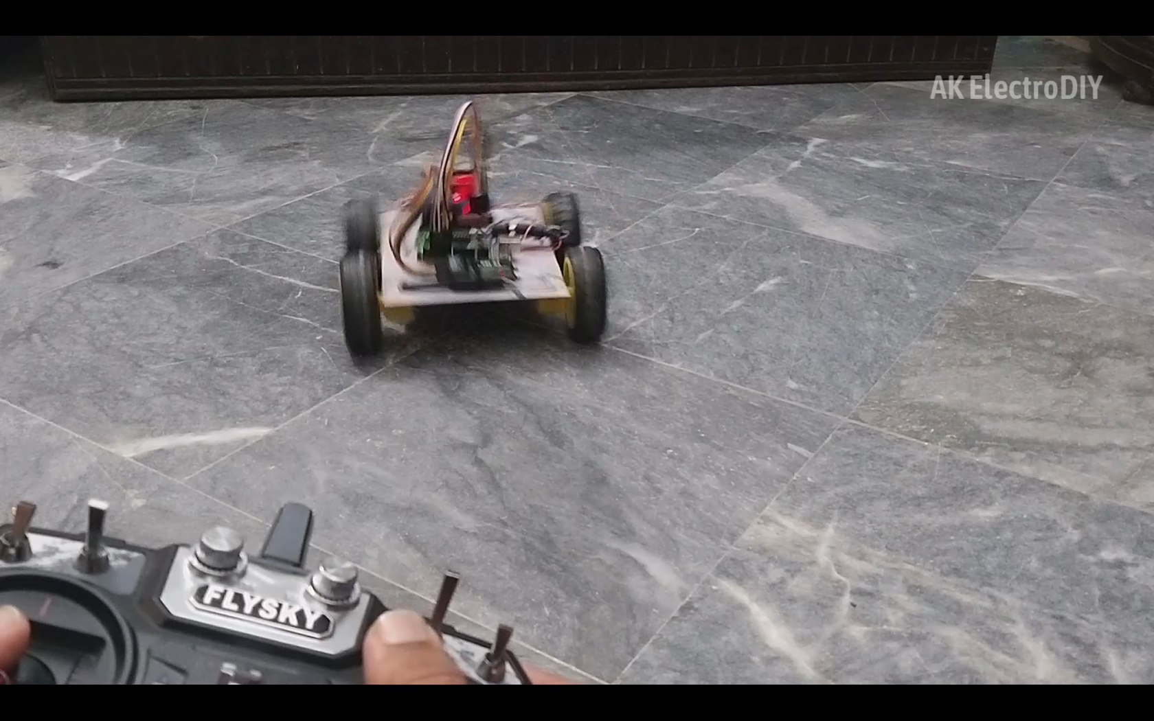.png)
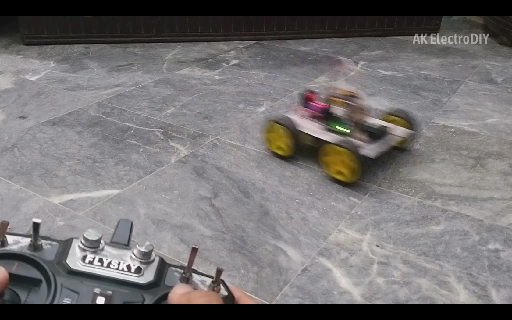
The car is now ready. We can play with it around and enjoy!