Arduino and the SSD1306 OLED I2C 128x64 Display
by tonygo2 in Circuits > Arduino
129970 Views, 47 Favorites, 0 Comments
Arduino and the SSD1306 OLED I2C 128x64 Display
Most Arduino owners soon decide that they would like to output text and results to a screen from their projects. Many opt for a two-line 1602 LCD display. They are easily available, inexpensive and there are plenty of guides to help set them up. Most go for the simple version that ties up many of their digital I/O lines and buy a device which is built for text but cannot display a graph or geometrical shape. The SSD1306 may be small, only 0.96 inch on the diagonal, but it is much more useful and only SCL and SDA have to be connected.
This OLED (organic light-emitting diode) device is a very clear, inexpensive mono digital display and is a very useful addition to an Arduino user’s collection of parts. I would not be without it and have bought several as they are cheap enough to leave embedded in projects. It is widely available from a variety of outlets, including Adafruit, who provide many of the libraries we will be using. It is an I2C device, and only uses two of the data pins, A4 and A5. It can be powered directly from the Arduino with 5V and GND. It will also run from 3V devices.
In this Instructable I am going to show you how to set it up and load the essential Libraries, explain the commands needed to program it and provide three example sketches:
- Using graphics
- Using Text
- A simple project combining text, graphics, analog input and asynchronous timed operations.
Supplies
You will need an Arduino and an UNO works just fine
SSD1306 - available from Ebay, China and many local suppliers
Connecting wires
10 K Ohm potentiometer
Connecting Up
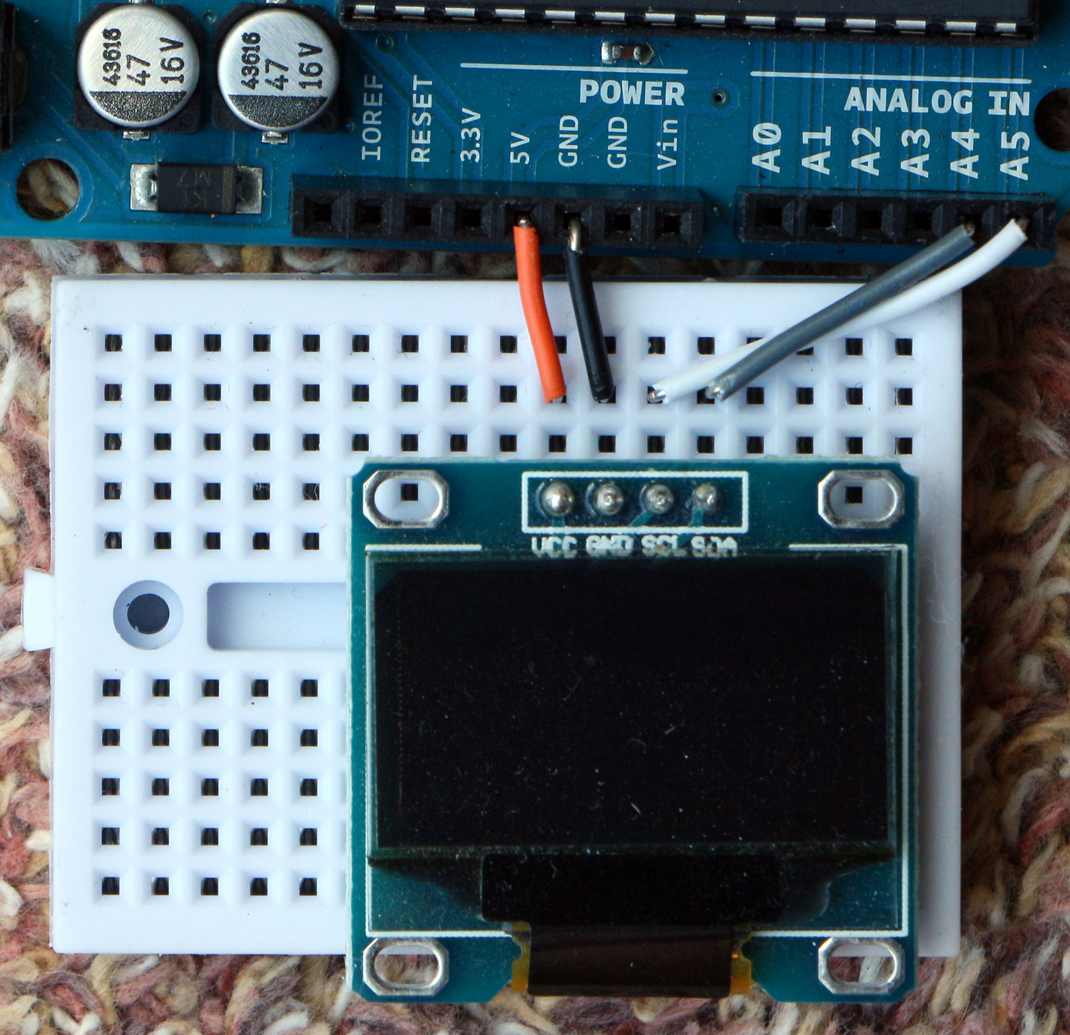
Make the following connections:
If you are using an UNO or a Nano connect VCC to 5V, GND to GND, SDA to pin A4 and SCL to pin A5.
If you are not using an Arduino UNO the SDA and SCL connections might be on different pins.
On a MEGA or Leonardo SDA goes to pin 20 and SCL to pin 21.
Take care as some SSD1306 boards have their pins in a different order – use the labels not the relative positions.
Check the I2C Address
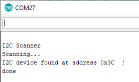
The next task is to check the I2C address of the SSD1306. There is a very useful Arduino script which can be downloaded from:
http://playground.arduino.cc/Main/I2cScanner
Copy the code, paste it into the Arduino IDE, save it, compile and upload it. Turn on the Serial monitor and check the address of your SSD1306 board. My board was 0x3C. Make a note of this as we will need it later.
Adding the Essential Libraries
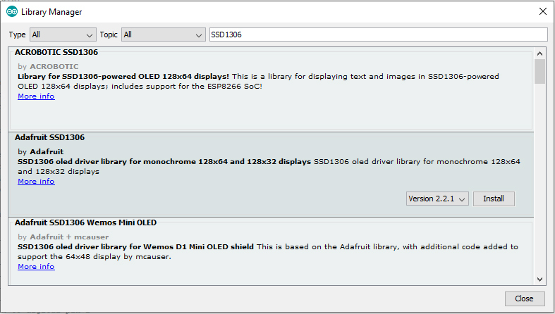
We now need to import the basic library for the SSD1306. I’m using the latest version of the Arduino IDE and it has library management built in.
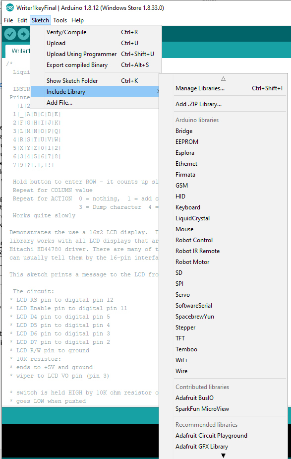
Start the Arduino IDE and navigate:
Sketch ==> Include Library ==> Manage Libraries… ==>
Type “SSD1306” into the box at the top right. We need the middle one – Adafruit1306 – so click on the Install button.
Get the Extra Libraries Needed
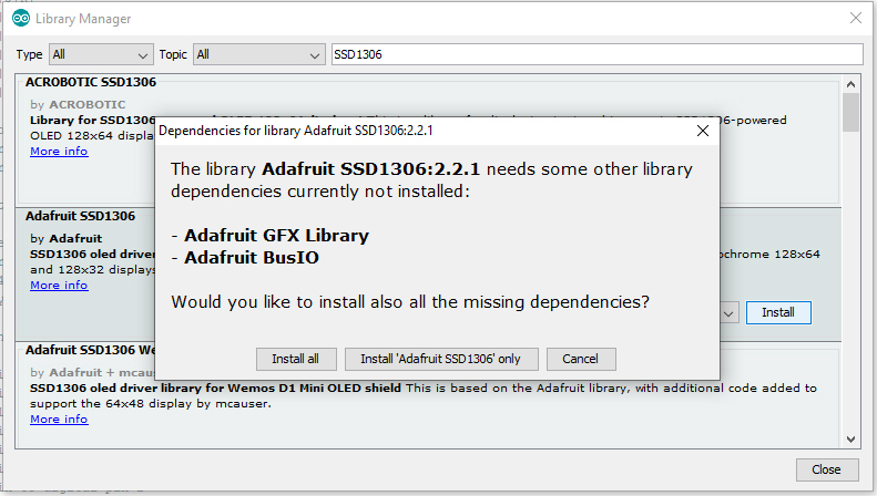
This brings up the screen above.
Click on the “Install all” button. Once this has finished go to Sketch ==> Include Library and check that the new library is available.
Test the Installation
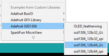
Navigate as follows:
Sketch ==> Examples ==> Adafruit SSD1306 ==> ssd1306_128x64_i2c
This will load a long script. Scroll down the program until you find the void setup() section and the line:
if(!display.begin(SSD1306_SWITCHCAPVCC, 0x3D)) { // Address 0x3D for 128x64
Change the 0x3D to your board’s address found earlier.
I changed mine to:
if(!display.begin(SSD1306_SWITCHCAPVCC, 0x3C)) { // Address 0x3D for 128x64
Once this has been done you can save the script with a new name such as ssd1306Demo, compile and upload the script to your Arduino. This is a very impressive demonstration and illustrates many features of the display and the library.
Library Methods
Many drawing and writing primitives are provided: single pixel plotting, lines, circles, triangles, rectangles (with square and rounded corners), and corresponding filled shapes. Text and numeric values, may be placed anywhere on the screen in a variety of sizes. Bitmapped shapes can be scrolled or moved about the screen and the whole screen can be rotated.
Points are defined by their Cartesian co-ordinates, (x, y). The origin (0, 0) is at the top left of the screen. Increasing the y value moves down the screen. The addressable dimensions of the SSD1306 screen are 128 pixels left to right (0, 1, 2, …, 127) and 64 pixels from top to bottom (0, 1, 2, …, 63). The pixel in the bottom right corner is (127, 63).
All the primitives have parameters which should be unsigned 16-bit integers (uint16_t).
(x0, y0) and (x1, y1) would define the first two positions, while h is the height and w the width of an object. A radius is r. All dimensions are in pixels. The colour is specified by c, SSD1306_WHITE or SSD1306_BLACK.
Graphical methods – draw is outline, fill is solid
fillScreen(c); Fill screen with colour
drawpixel(x0, y0, c);
drawline(x0, y0, x1, y1, c;)
drawFastVLine(x0, y0,l,c); Fast vertical line of length l
drawFastHLine(x0, y0,l,c); Fast horizontal line of length l
drawRect(x0, y0, w, h, c);
fillRect(x0, y0, w, h, c)
drawRoundRect(x0, y0, w, h, r, c); Rounded corners of radius r
fillRoundRect(x0, y0, w, h, r, c); Rounded corners of radius r
drawCircle(x0, y0, r, c);
fillCircle(x0, y0, r, c);
drawTriangle(x0, y0, x1, y1, x2, y2, c);
fillTriangle(x0, y0, x1, y1, x2, y2, c);
Example: large solid circle
display.fillCircle(63, 32, 30, SSD1306_WHITE); // Centred, white circle of radius 30 pixels
display.display();
Text methods
These are based on the system used for printing to the Serial monitor with print() and println(). The font included with the library is 5 pixels wide and 7 pixels tall but prints into a 6x8 pixel space.
drawChar(x, y, char, color, bg, size); // bg = background colour, char = ASCII no
setCursor(x0, y0); Top left corner of the character
setTextColor(c);
setTextColor(color, backgroundcolor);
setTextSize(size); 1 (default), 2 or 3
setTextWrap(True or False);
The Most Important Bit
None of these instructions will produce a change on the screen without a display.display(); method. If your script does not appear to be working check you have included this line at the bottom of your screen changing code.
Example Sketches - GFX #1
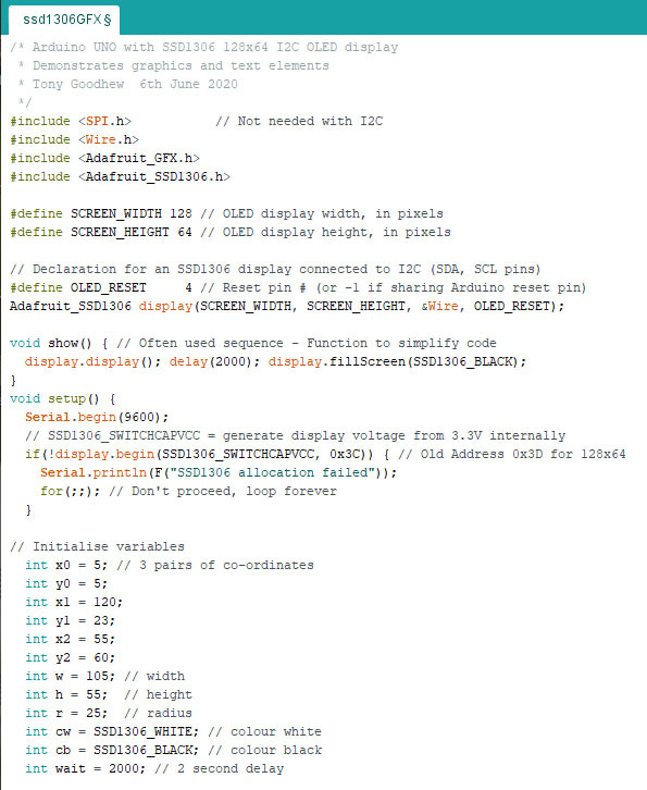
I'm going to provide three examples to help you get started. The first illustrates the graphics. You do not need to type in the sketch a download will be provided for each sketch.
The top of the program appears above. You do not need to include the SPI.h if you are using a I2C device, but Adafruit have supplied dual interface boards so include it in their example sketch.
When writing your own sketches you need all the lines down to the initialise variables comment to load the libraries and set up communication with the SSD1306 board.
Downloads
GFX #2
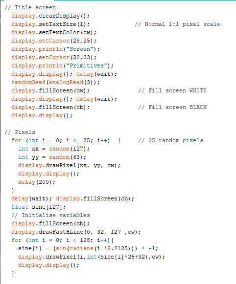
This section sets up a Title screen, draws 25 random pixels and draws a sine curve on the screen.
GFX #3
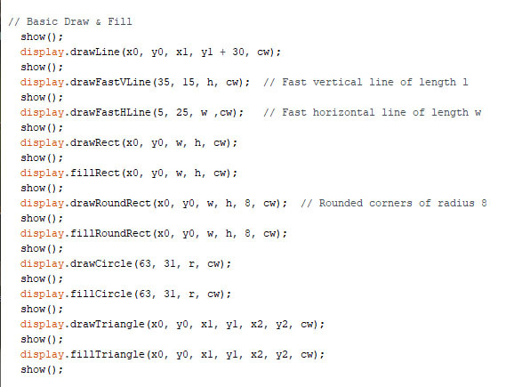
This section illustrates the basic draw (outline) and fill (solid) routines available.
GFX # 4
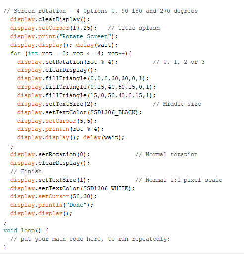
This shows how to rotate the screen and writes a finishing screen.
Please download and run the sketch on your setup.
Playing With Text #1
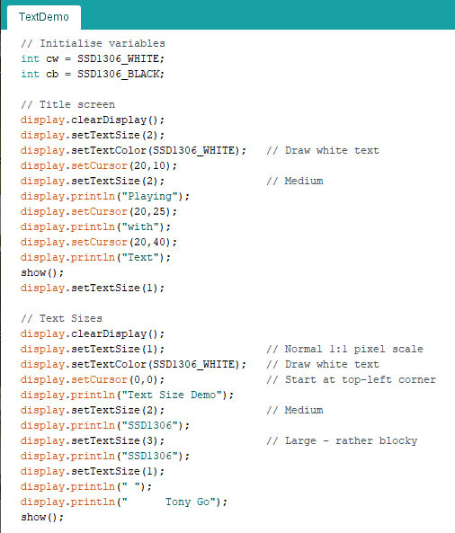
Using the same starting sequence as the previous example we are now going to look at the text facilities available.
This sketch displays a title page using expanded text and shows the three sizes available on a single screen.
You can download the whole sketch here.
Downloads
Playing With Text #2
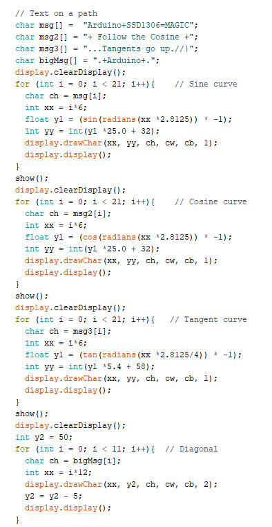
Here we plot messages onto Sine, Cosine and Tangent curves and larger characters onto a diagonal.
Playing With Text #3
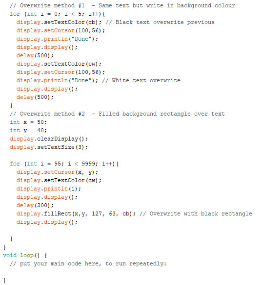
As the sketch runs you may want to update either the whole screen or just some parts of it. You can clear the screen, write the same text directly over the existing text in the background colour to make it disappear or place a background coloured filled rectangle over the text before writing something new. This page demonstrates the last two methods.
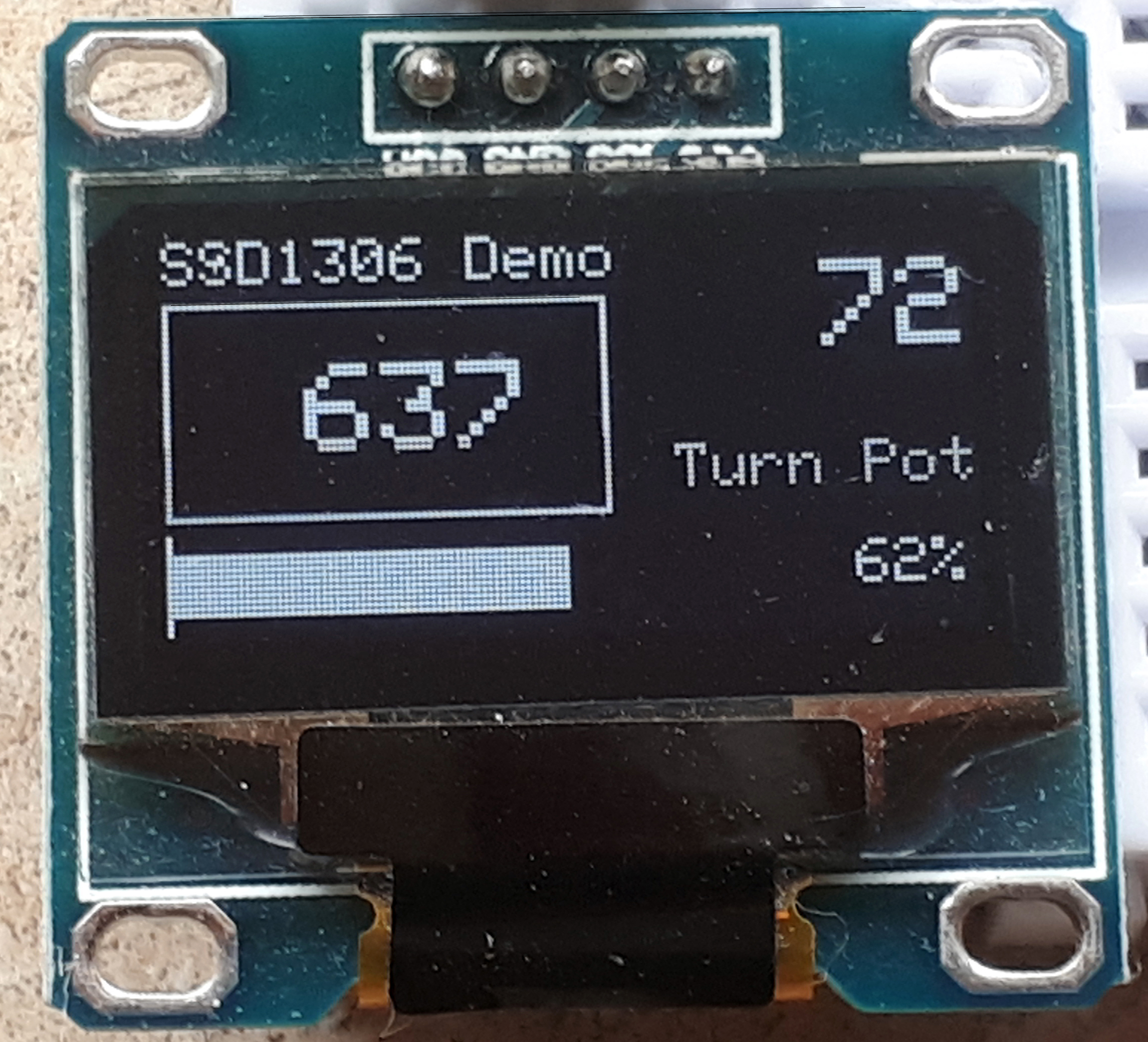
3rd Sketch - a Little Project
You will need to add a 10K Ohm potentiometer to the circuit for this stage. Connect the centre connection to Analog pin A0 and the outside contacts to 5V and GND. Twisting the pot will allow us to provide a changing voltage as input to the sketch.
There are two things going on:
- a one second timer clicks on in the top right hand corner.
- as the pot is turned the bar graph changes length, the Raw Pot value (0... 1023) is displayed in the box and the percentage of maximum value is displayed at the end of the bar graph.
As we want the graph to constantly update values on the screen we cannot use the delay(1000) method of counting the seconds.
Two things happen in the main loop. On each pass the pot is read and the screen updated with the three new values and the millisecond timer is checked to see if a second has passed since it was last updated. Only if the 1000 milliseconds have passed do we update the timer value.
Project #1
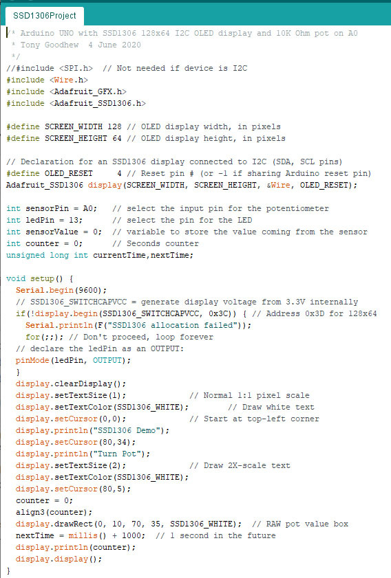
This sets up the devices, the screen and sets the time at which the second timer needs updating.
Downloads
Project #2
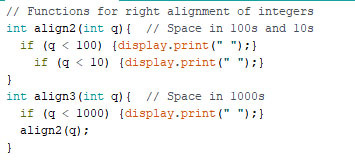
I want the changing numbers to appear to be right aligned. To do this we need at insert "space" characters in front of short values. These two functions print the blank space as necessary.
Project #3
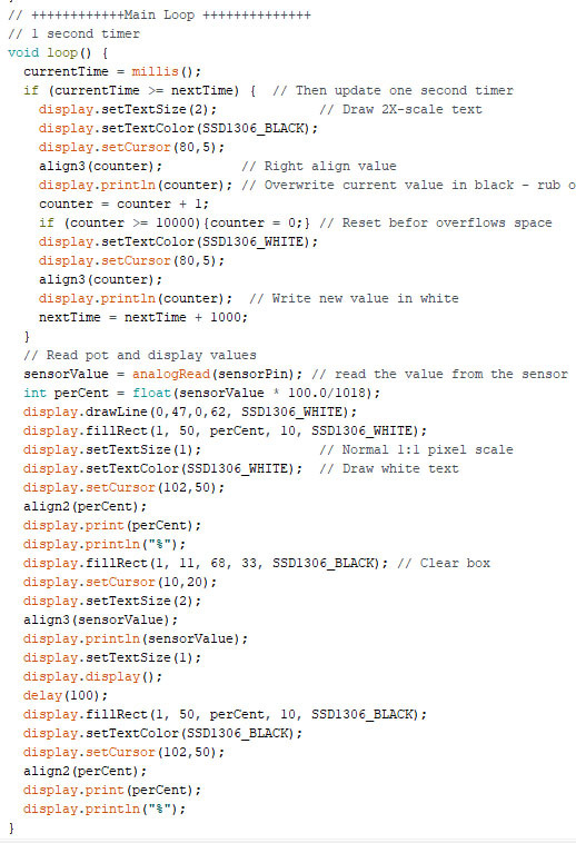
This is the main loop which does all the heavy lifting. The first half checks to see if it is time to update the second counter at the top right of the screen. Most of the time it skips the rest but every second it carries out the update. This is a very useful method of appearing to be doing two things at once, especially when one action needs to be carried out much more frequently than the other.
The second half reads the pot, calculates the percent value and updates the various parts of the screen. This is quite time consuming.
Please note that the whole screen is never cleared and re-drawn.
I hope you have found this Instructable useful and that you find the little SSD1306 display as useful as I do.
I'm happy to receive comments/feedback.
There is more information and some more of my programming examples and tips on LCD displays with Arduinos here: