Arduino and HC-SR04
In this tutorial we are going to learn how to use ultrasonic sensor by creating three interactive mini-projects. The last project shows how to create a basic object avoidance robot.
Supplies
- Ultrasonic Sensor HC-SR04
- Arduino Uno (or similar)
- LED (any color)
- 150 Ohm Resistor (or any from 50-350 Ohm)
- Buzzer (5 V, but any can work as long as you deliver the current/voltage)
- L298N Motor Driver
- TT Brushed Gear Motor (6 V)
- 4 x AA/AAA Battery Pack (circa 6 V)
Wiring With an LED
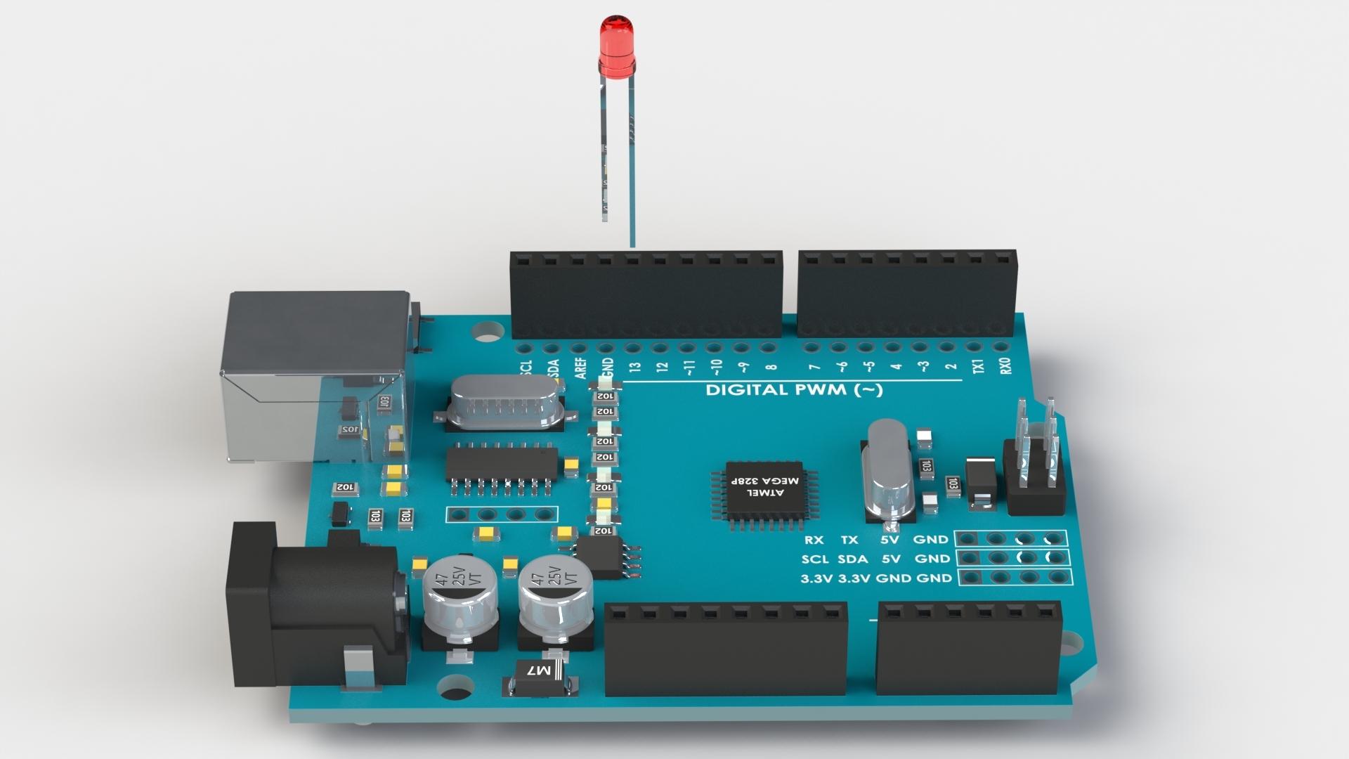
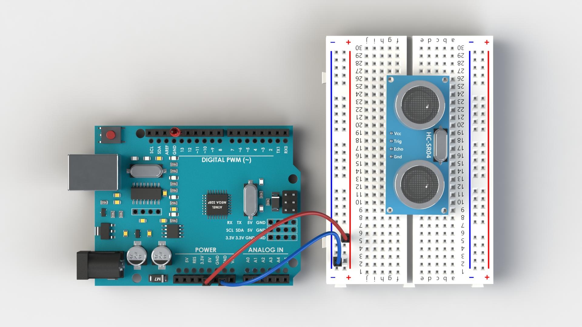
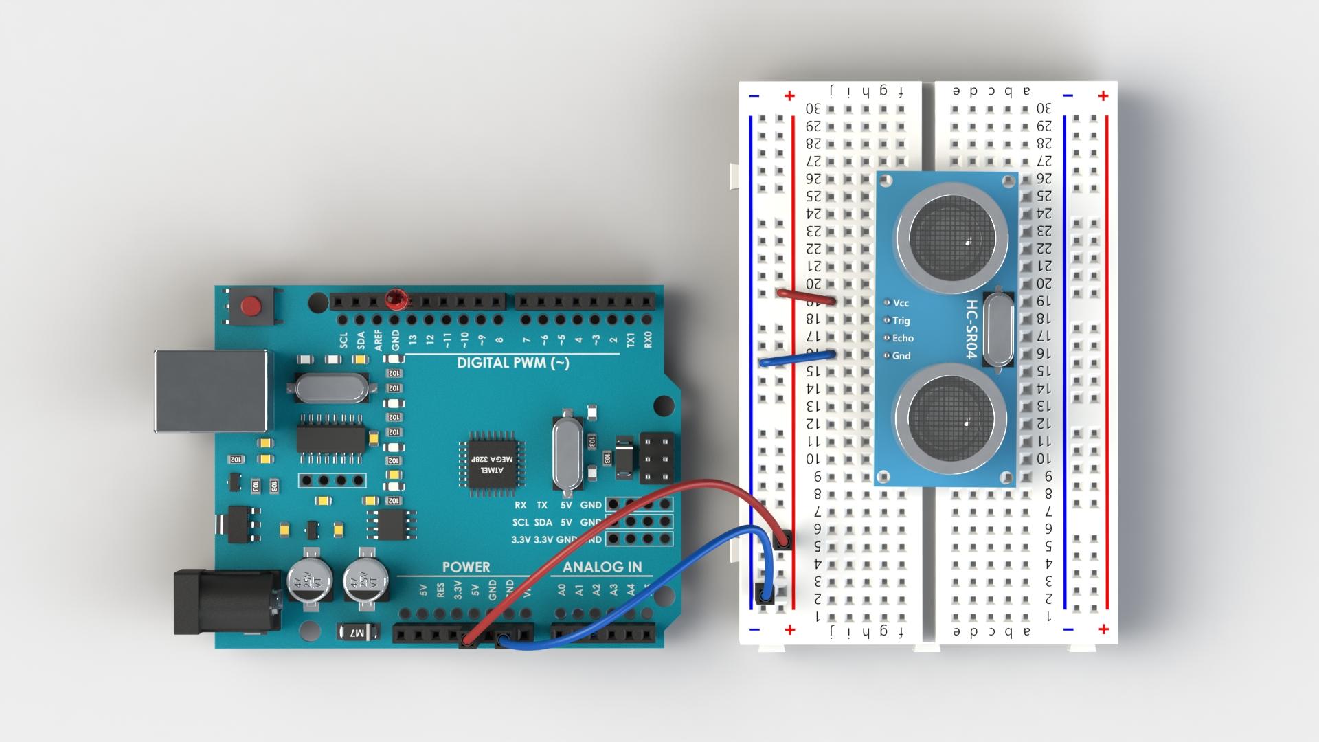
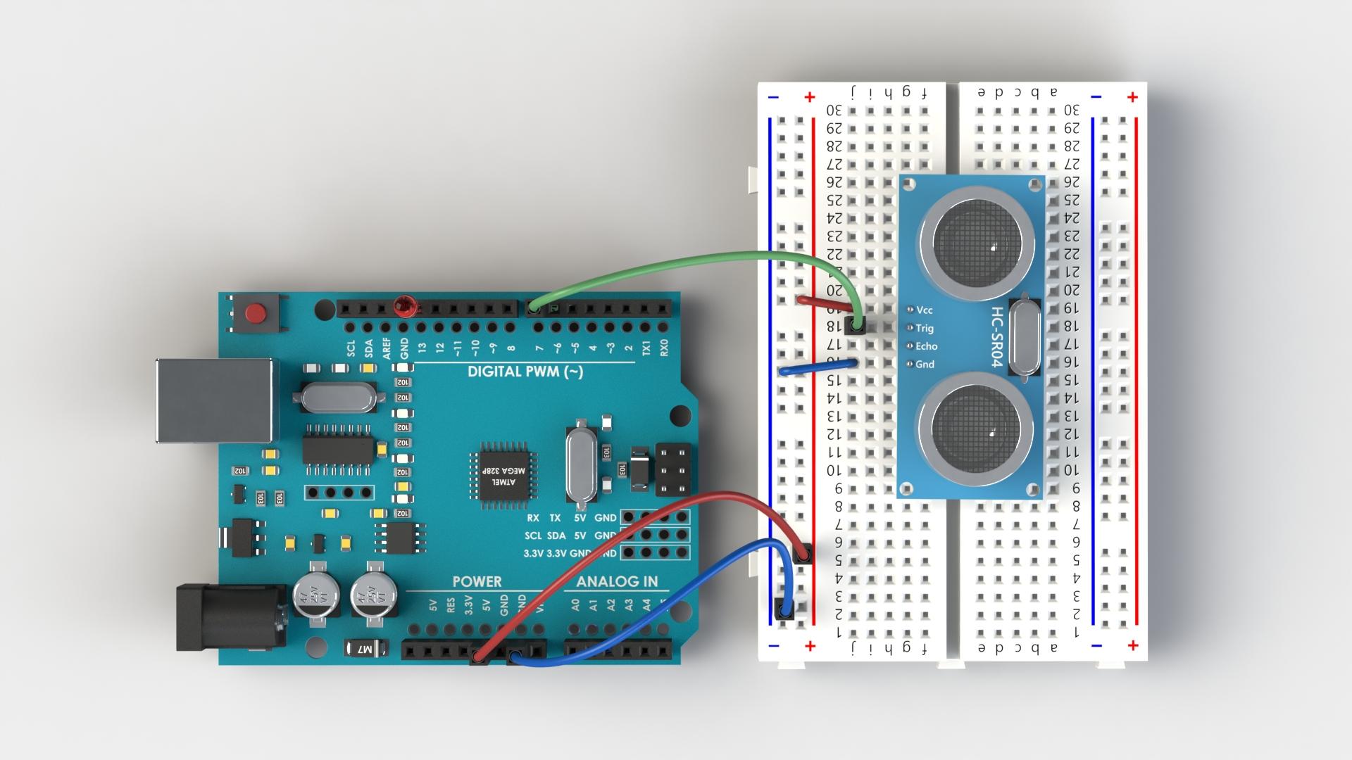
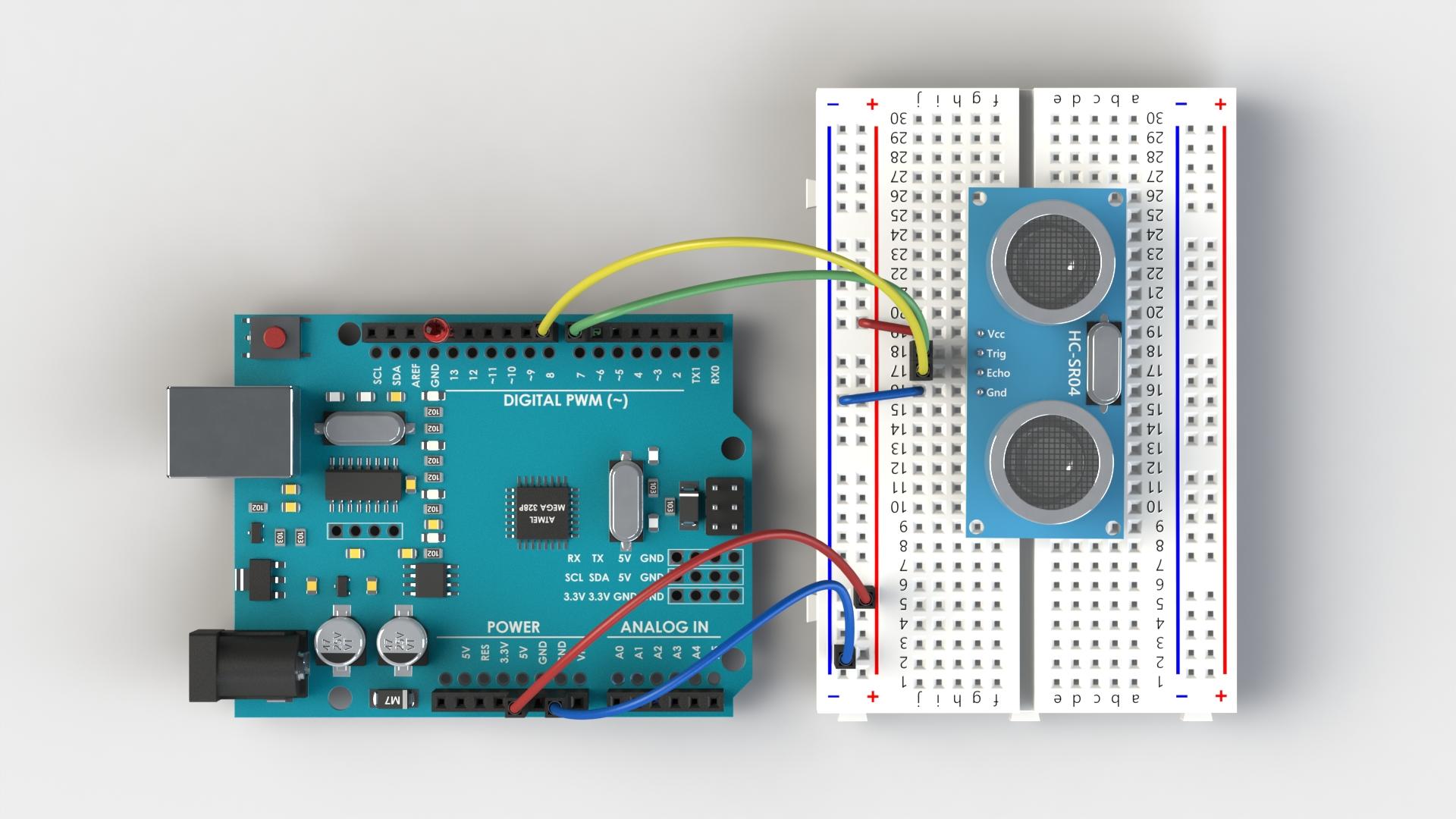
We are going to connect the HC-SR04 with the LED, the LED will signal us if an object gets too close (around 15 cm) to the sensor. To use this tutorial you can either browse through the images and connect the components as shown, following the order of images as shown, or you can read and follow the images.
- First we will connect the LED directly to the Arduino, the long "leg" of the LED goes to the digital pin D13 and the short "leg" goes to the GND (ground). (Image 1)
- Now we will connect the HC-SR04 with the breadboard, here I have straightened the pins on the HC-SR04 to be visually clearer. Connect the GND of the Arduino to the - on the breadboard and +5 V of the Arduino to the + on the breadboard. (Image 2)
- Connect the Vcc of the HC-SR04 to the + of the breadboard, and GND of the HC-SR04 to the - of the breadboard. (Image 3)
- Connect the Trig pin of the HC-SR04 with the digital pin D7 of the Arduino. (Image 4)
- Connect the Echo pin of the HC-SR04 with the digital pin D8 of the Arduino. (Image 5)
Now that we have finished with the wiring, we will connect the USB cable to the Arduino and Program the behavior of the Arduino.
Programming a HC-SR04

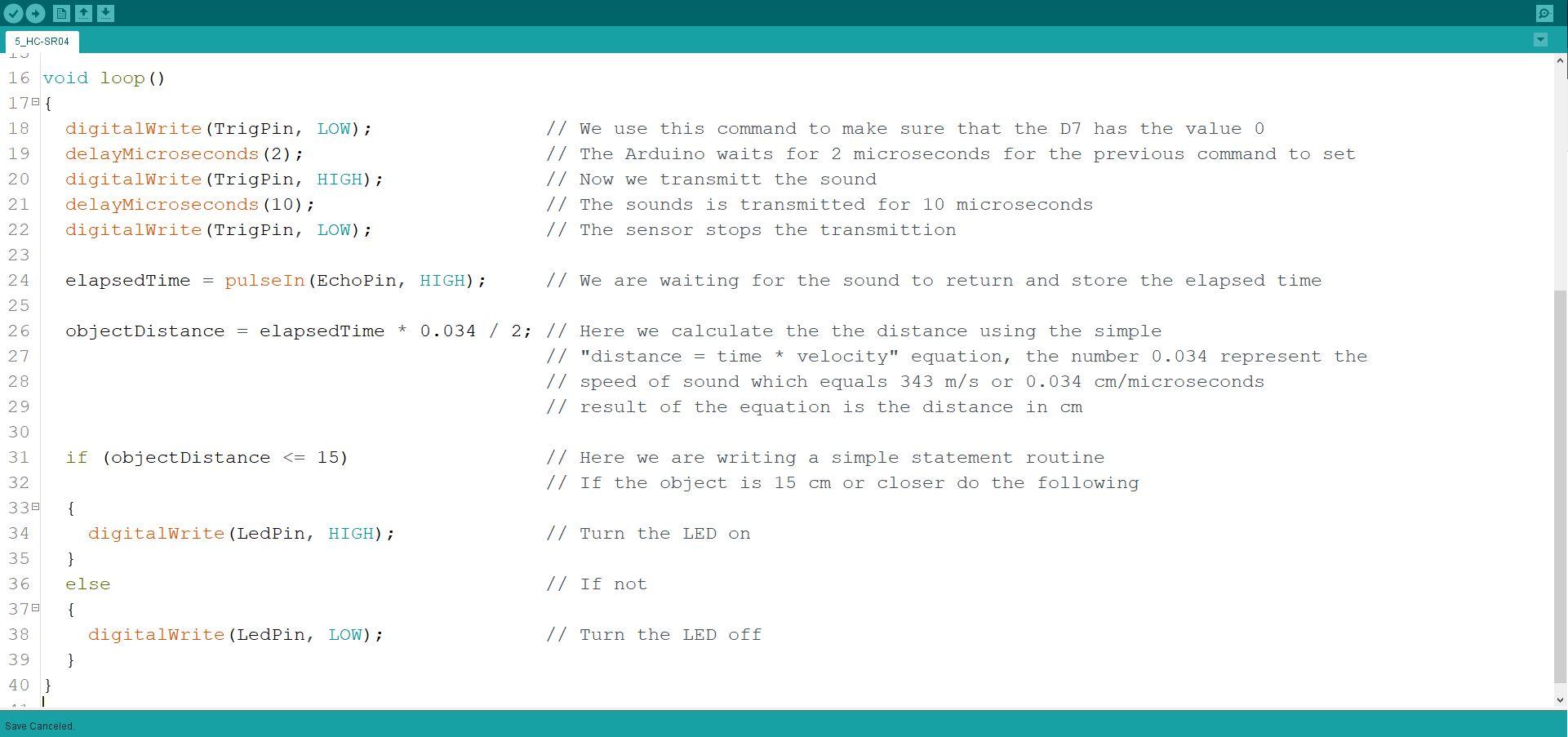
To see the code simply download it down below and open it with you Arduino IDE. Each step of the code is explained in detail.
- First we setup the variables for chosen digital pins in the wiring part of the tutorial. (Image 1)
- Then we define the variables for the equation that we are going to need later on. (Image 1)
- We setup the modes of the pin to be output or input as appropriate. (Image 1)
- Now we are going to write a main function used with the HC-SR04 sensor. (Image 2)
- And lastly we are going to make a simple if statement to turn the LED on or off. (Image 2)
Please read the detailed explanation in the code directly, it's much more intuitive to see it in the code.
Downloads
Wiring With a Buzzer
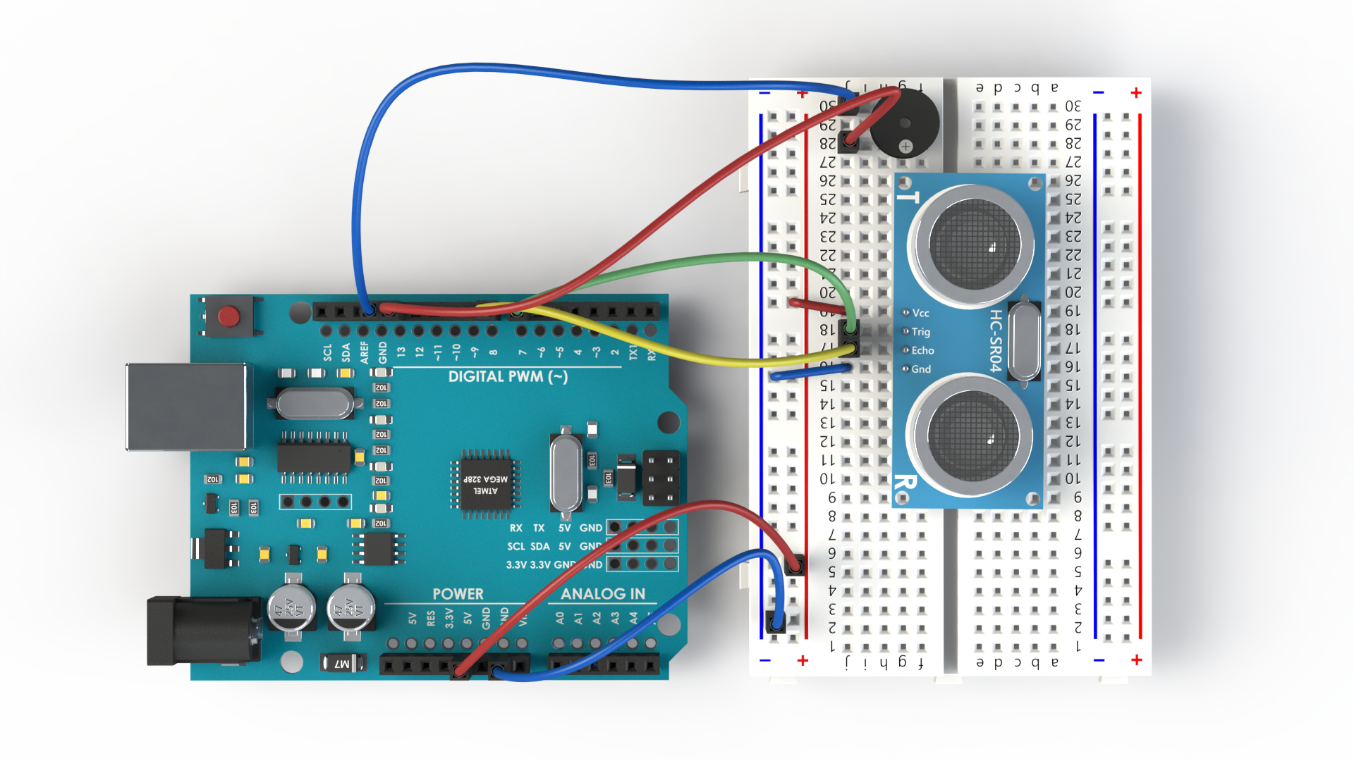
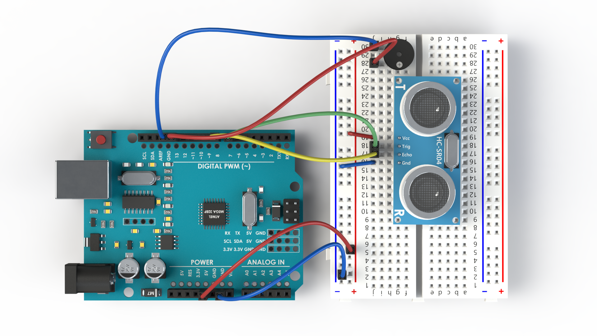
The wiring here is almost identical to the wiring with the LED. We are simply going to use audio output (Buzzer) instead of visual output (LED) to signal whether an object is too close to a sensor. This example approximates a burglar alarm.
- There is only one additional step in this part of the wiring. Simply remove the LED from the GND and D13 and connect the Buzzer in the same place. Here I have used additional two jumper wires to connect the Buzzer with the Arduino through the Breadboard. (Image 1)
The Buzzer "cares" about polarity in the same way that the LED does, meaning we need to connect the + side of the Buzzer with the D13. The + on the Buzzer is usually depicted with the difficult to read black + on the buzzer, here in the image I have colored it white to be more visible.
Programming a Buzzer
The program is the same as the one with the LED, you can rename the variable from LedPin to BuzzerPin if you want. When you test the code you will notice that as you approach the sensor with your hand the buzzer will start to make noise, when you remove your hand the buzzing will stop.
Wiring With a L298N
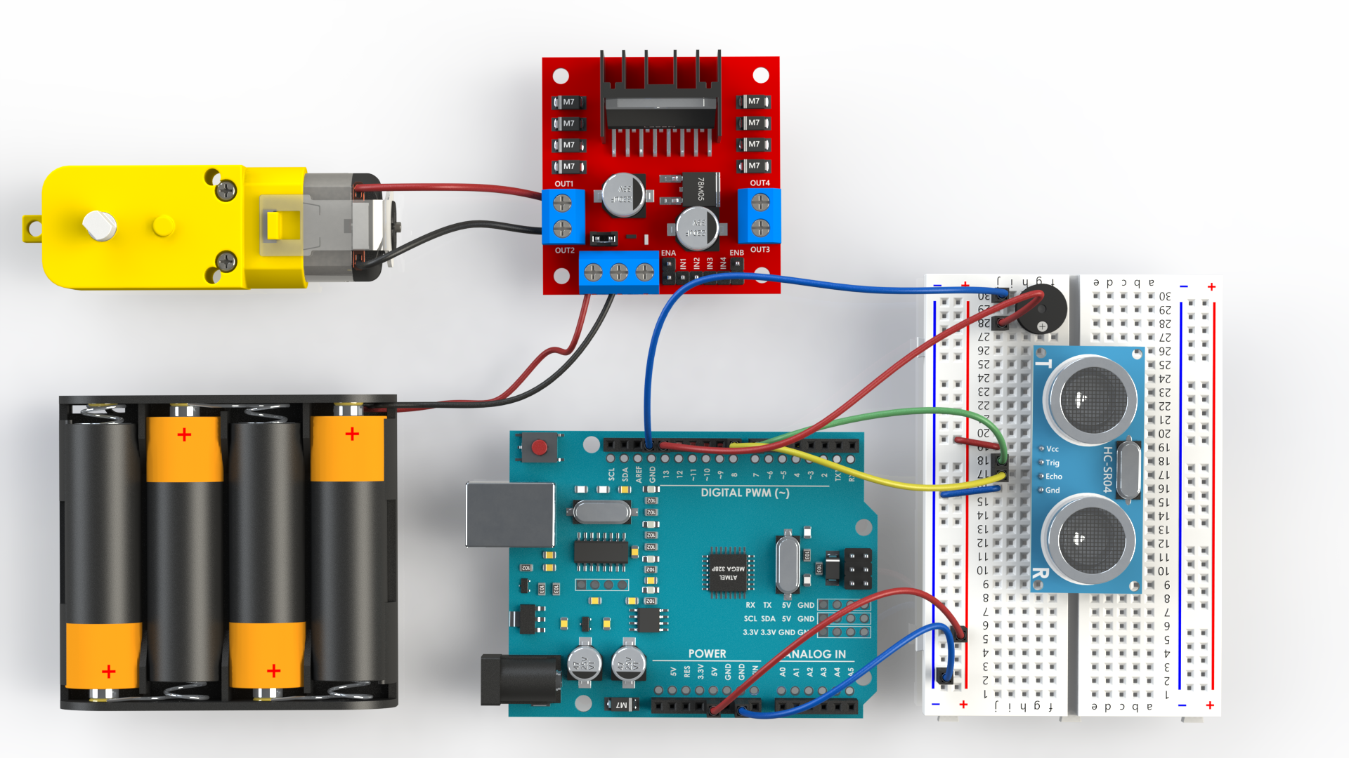
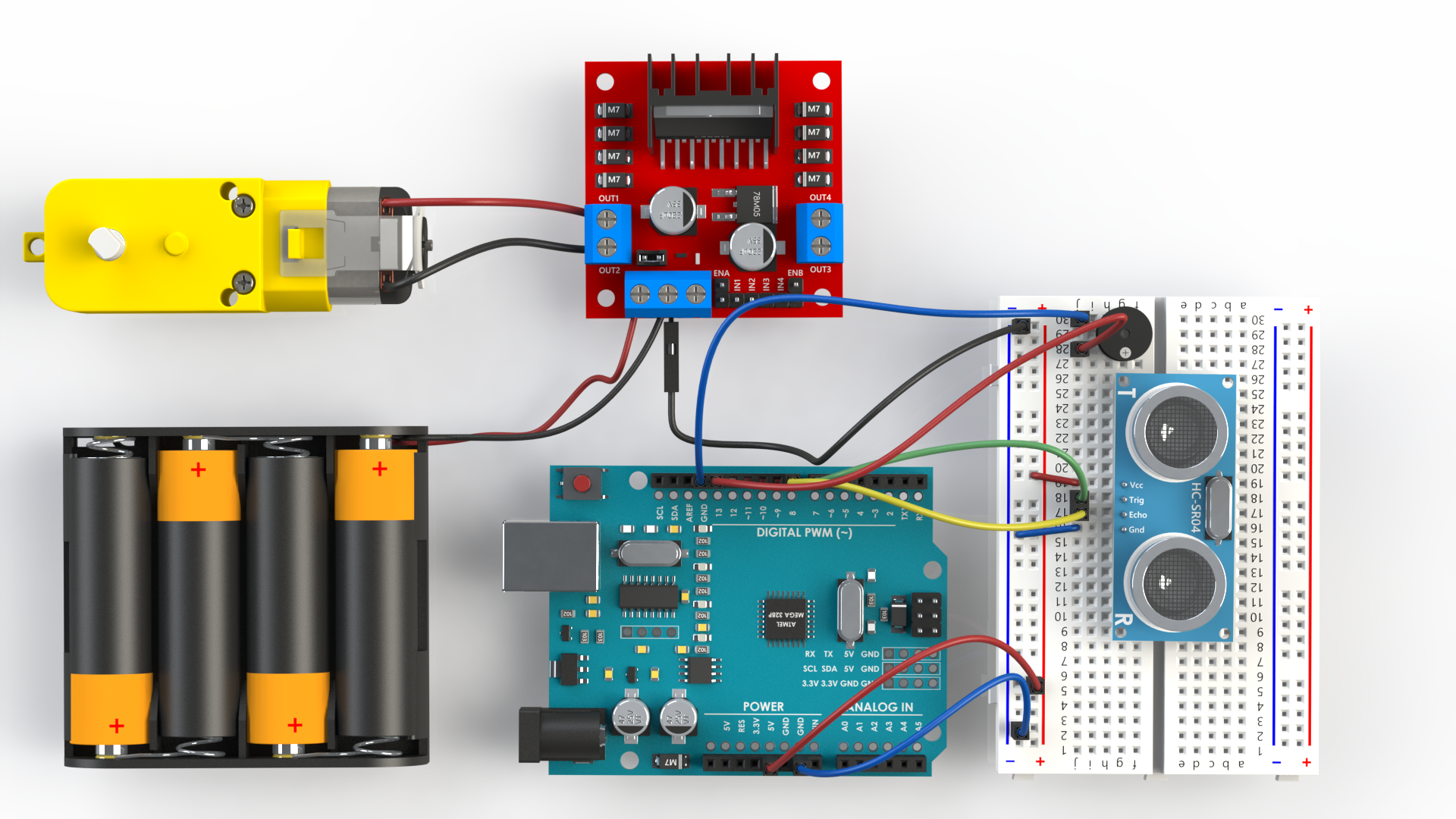
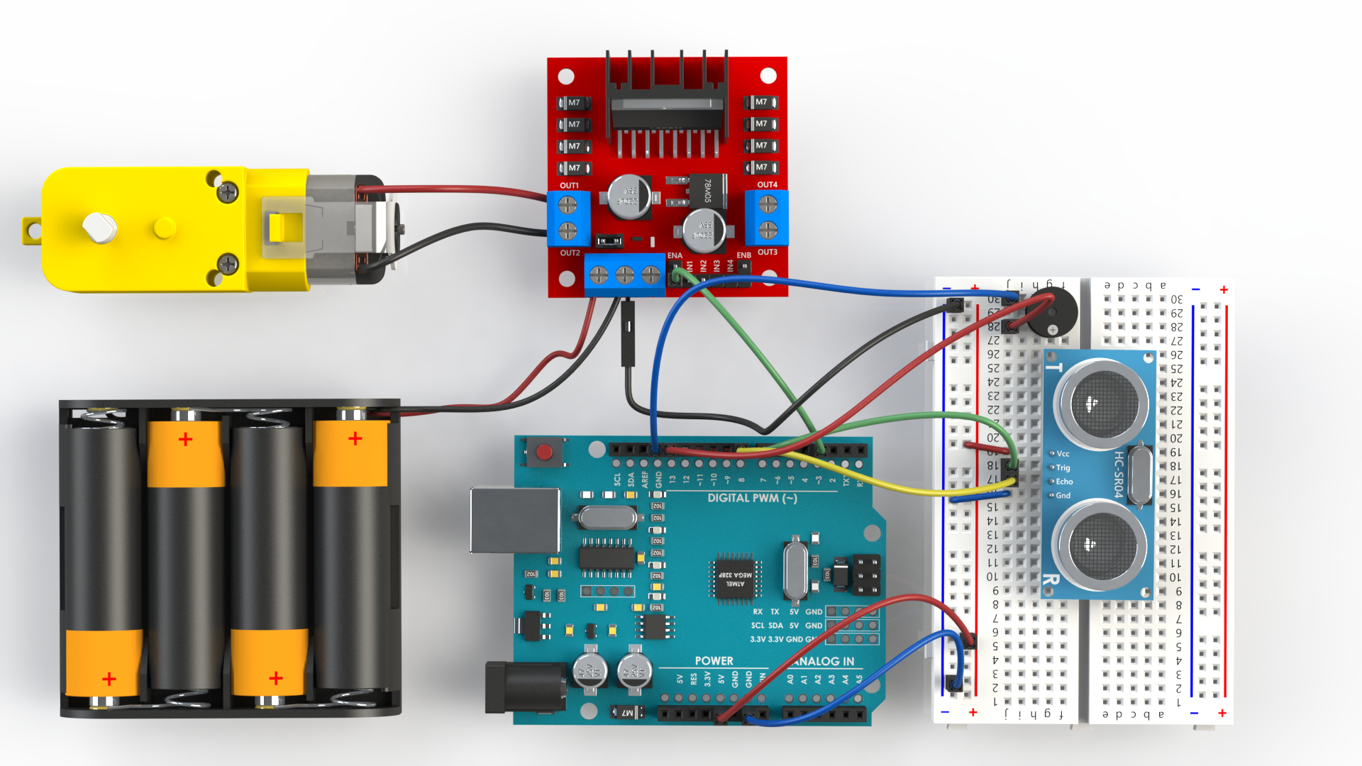
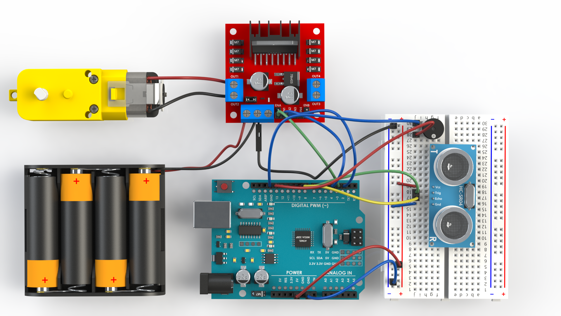
Now we are going to combine the previous example with a simple Gearmotor which is run by a L298N motor driver. Here we will see that when the sensor value drops below 15 cm that the motor runs backwards for a second, usually you would want to program your robot to go backwards and turn by X degrees and again try to move forwards to see if the object is no longer in the way. (similar algorithm is used in robot vacuum cleaners).
- First we connect the motor and the battery to the L298N as shown in our Arduino and a PWM tutorial. (Image 1)
- We will then connect the GND of the L298N and the GND of the Arduino through the breadboard. (Image 2)
- Connect the ENA pin of the L298N to the D3 pin which is able to give PWM. (Image 3)
- Connect the IN1 from L298N to D2 on the Arduino and IN2 from L298N to D4 on the Arduino. (Image 4)
Now that we have connected it all together we will start to program the simple routine.
Programming a HC-SR04 With a L298N
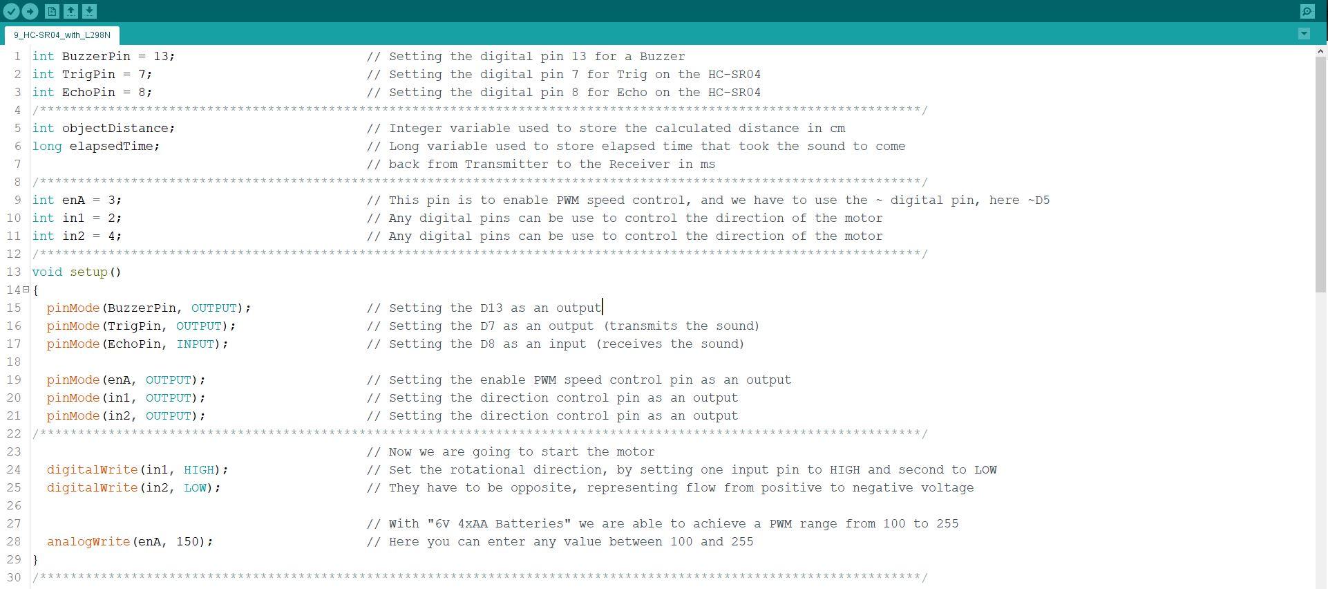
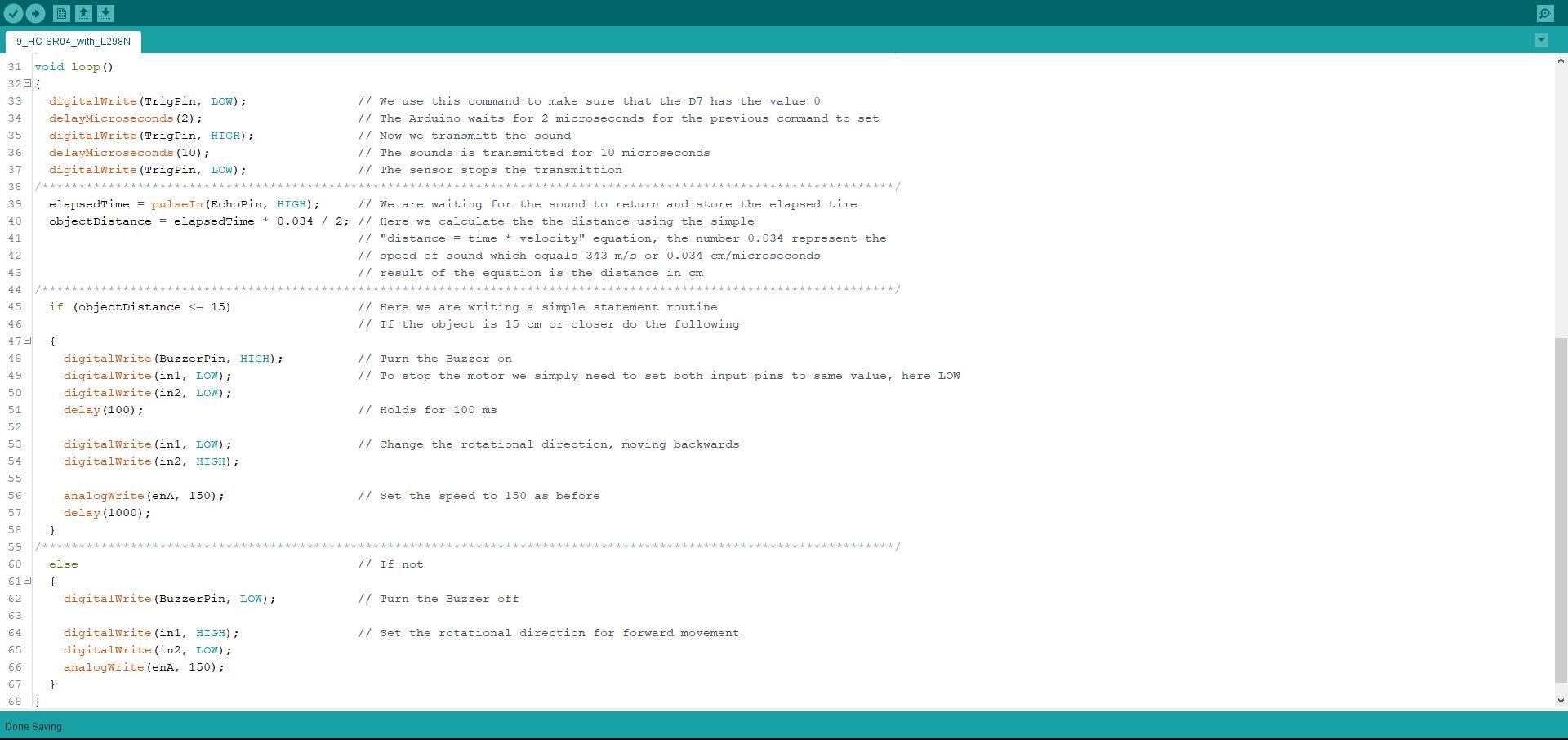
When a robot encounters an object it's common for the robot to have pre programmed reaction to the event. Here the Gear Motor will start to spin in the opposite direction signaling backwards movement when an object is encountered.
There are only small additional line of codes here added to the previous HC-SR04 program.
- First we had to define the pins used to control the motor. (Image 1)
- We had to define the mods of this pins and start the motor running in the "forward" direction. (Image 1)
- In the if loop we have added the action for each case, first if the object is less than 15 cm from the robot, move backwards. (Image 2)
- If the object is more than 15 cm away from the robot, the robot will continue to move forwards. (Image 2)
Of course this routine is only an example, to get the robot moving we would need two motors in the same loop and instead of just going forwards and backwards we would adjust the routine for the robot to move backwards first after encountering the object, then turn in the desired direction for about 15-30 degrees and than move forwards, the robot would repeat this action until it's clear of the object and it can pass. To see this in action check the video below.
Downloads
More!
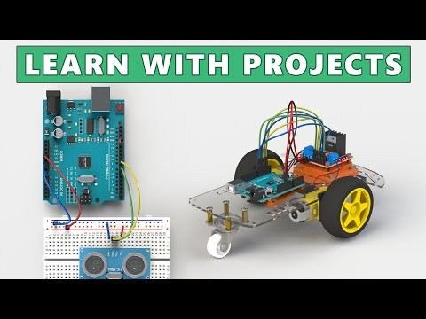
In the second part of the video you can see the wiring of an HC-SR04 with the LED, you can also see the project in motion same as other interesting projects related to this tutorial.
If you have enjoyed this tutorial, please consider subscribing to my youtube channel to support me.