Arduino Uno - Flame Sensor
by ChristianL84 in Circuits > Electronics
4763 Views, 38 Favorites, 0 Comments
Arduino Uno - Flame Sensor
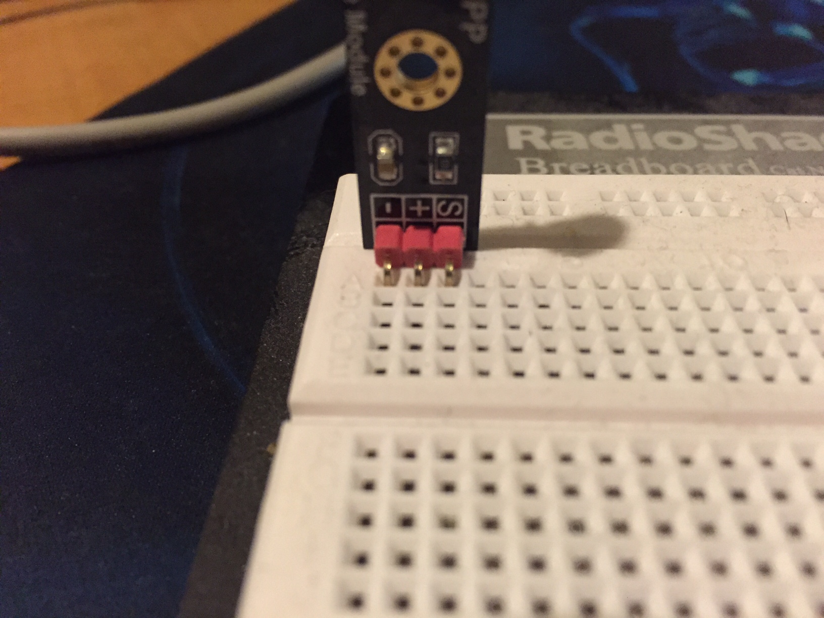
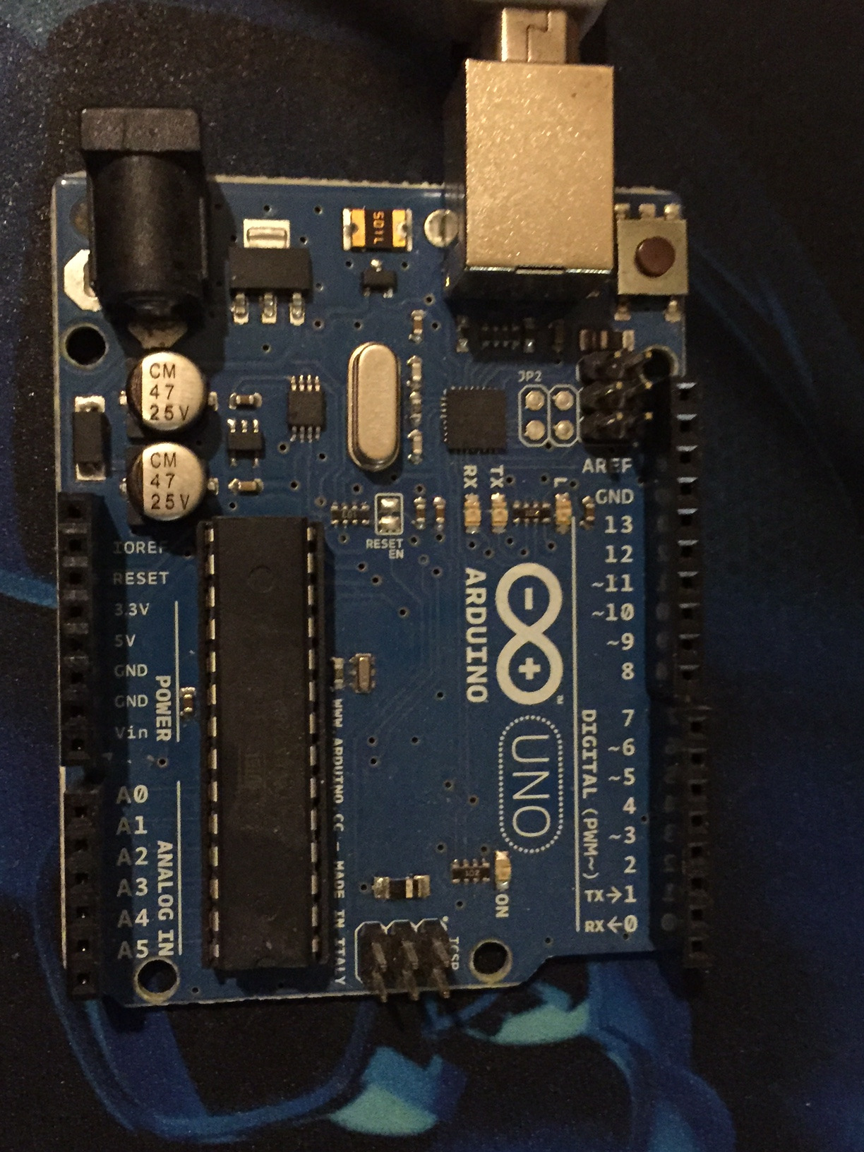
In this Instructable, I show how I wired, programmed, and view a OSEPP Flame Sensor with my Arudino Uno.
This little device is going to come in handy with my future goals in automation, as well as some neat around the house hacking!
I hope you enjoy!
(I apologize in advance for using the same pictures multiple times)
Gather Materials:


First off, you will have to gather the materials needed for the project.
* Arduino - I used an UNO, but I am sure most models will work fine. This simple project only needs power and an Analog Input, so make sure your board has those options
* Sensor - OSEPP Flame Sensor:
http://osepp.com/products/sensors-arduino-compatib...
* (5) Jumper Wires - You can use stripped Cat5 or any other wire you want. I am using some jumper wires I had lying around
* Breadboard - I am using one that I bought at my local RadioShack before they closed shop. It is larger than needed, but it gets the job done!
* Arduino IDE
Physical Side - Flame Sensor Installation
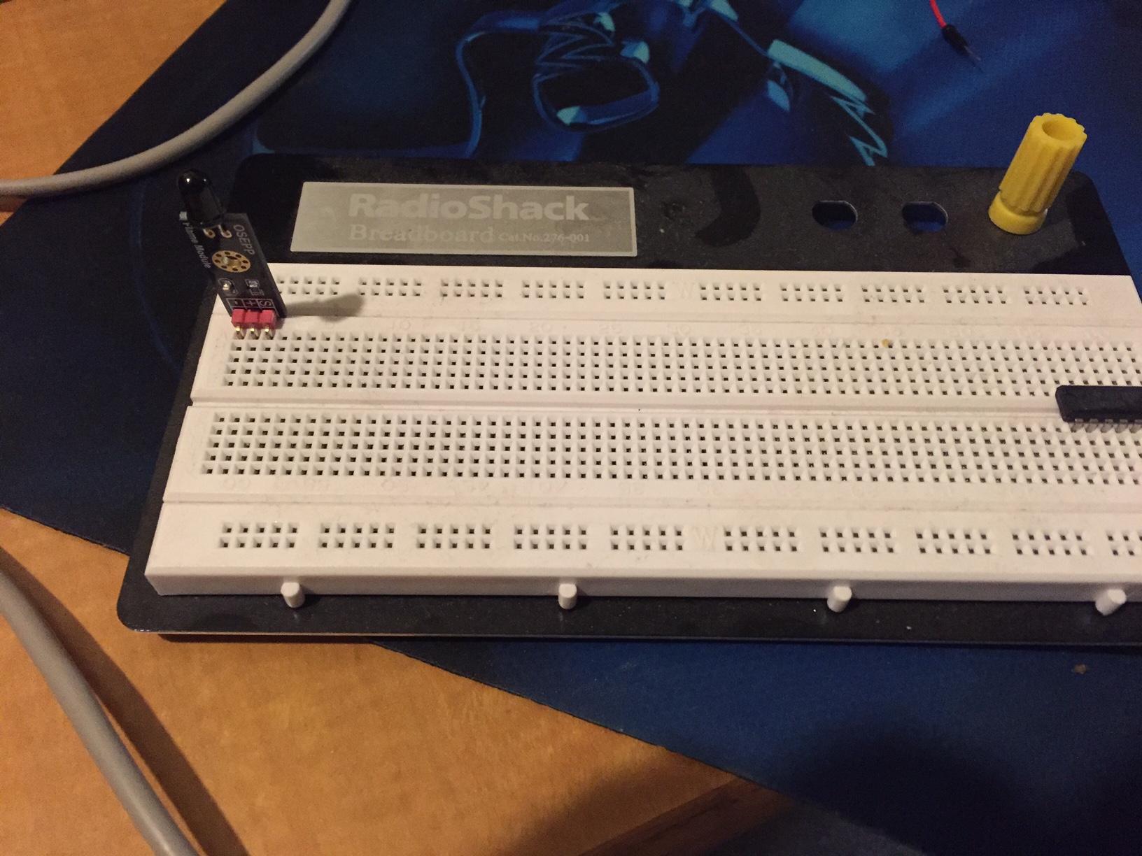

Now comes the fun part... putting it all together!
The first step is to plug your Flame Sensor into (3) Rails. Make sure that you do not plug the sensor into the same rail on all (3) pins. This will cause your sensor to be shorted out, and can damage the sensor.
Physical Side - Wiring
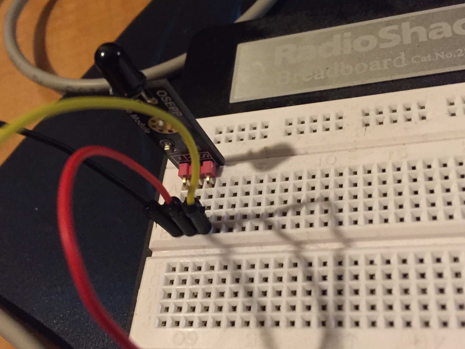
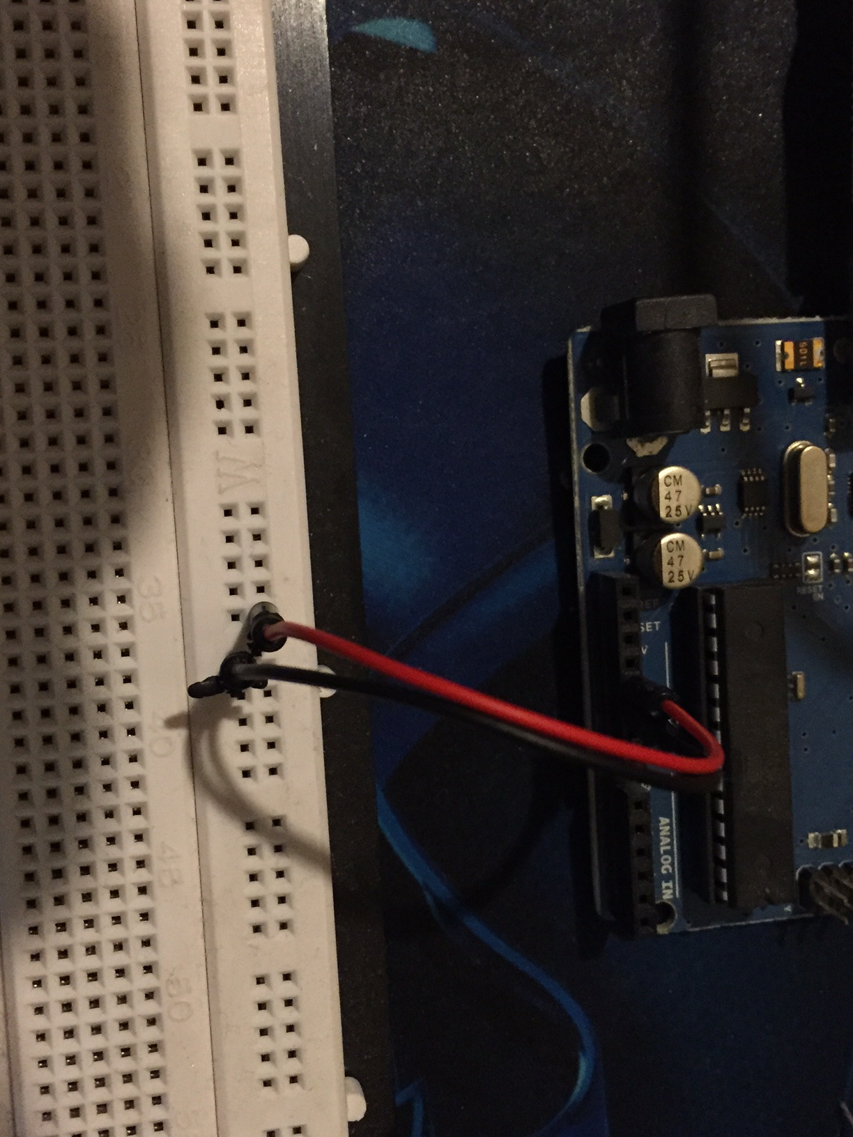
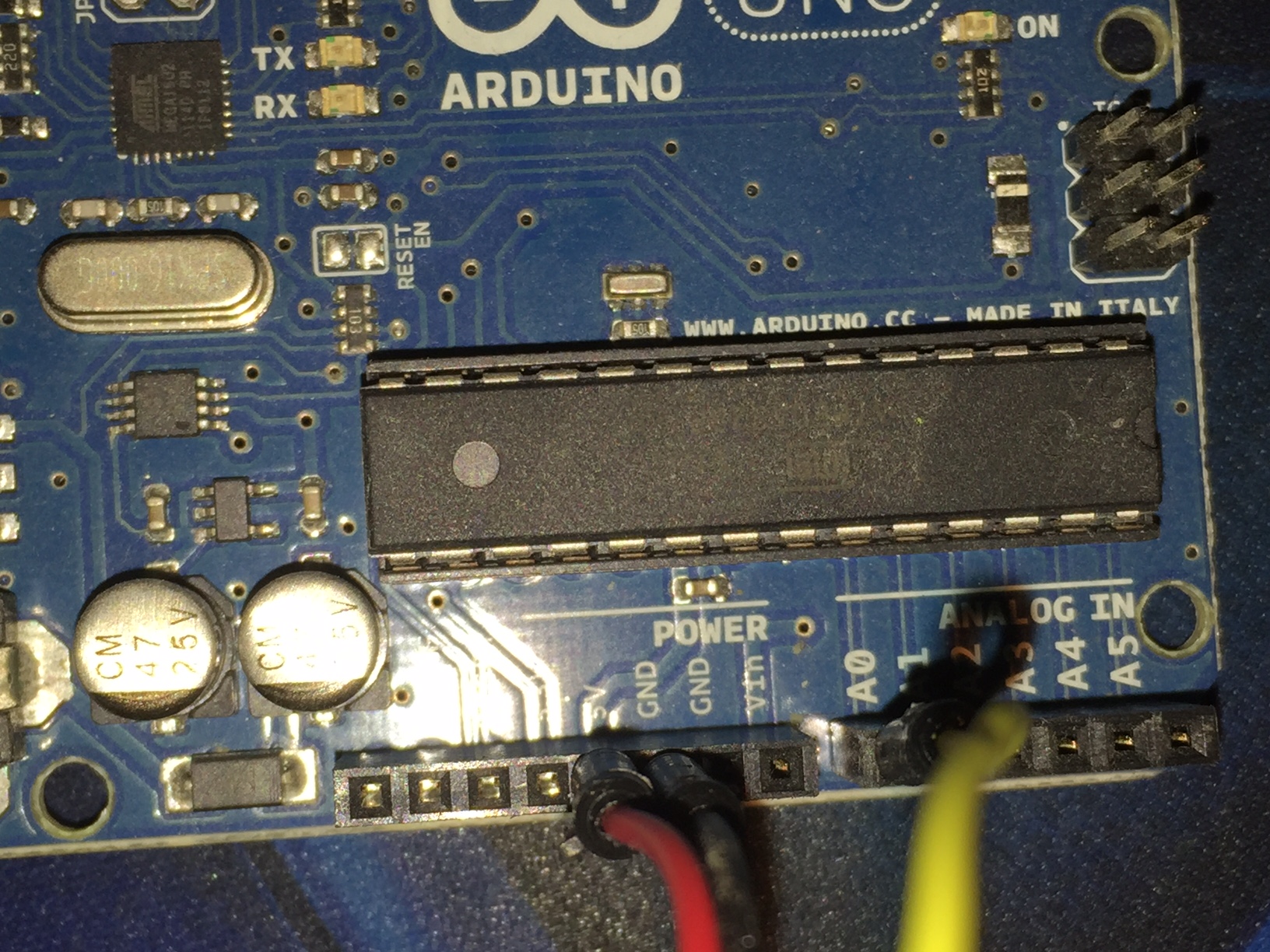
Next we need to connect the following wires:
1) I hooked a RED jumper wire from the + side of my sensor to the + rail of my bread board
2) I hooked a BLACK jumper wire from the - side of my sensor to the - rail of my bread board
3) I hooked another RED jumper wire from the + side of my bread board to the 5V Pin on my Arduino
4) I hooked another BLACK jumper wire from the - side of my bread board to the GROUND Pin on my Arduino
5) I hooked a YELLOW jumper wire from the Sensor Output (Analog) side of my sensor to the A0 (Analog 0) Pin on my Arduino
You do not have to use the same color wire, but I like to make sure that I use somewhat of a standard, even if it is my own. I try to use RED for Voltage, BLACK for NEGATIV/GROUND, and YELLOW for Analog.
Coding - Arduino Code
Time for the brain part!
Here is the Arduino Sketch that I wrote for this program:
int analogPin = 0;<br>int val = 0;
void setup() {
  Serial.begin(9600); //Serial Port 9600
  pinMode(13, OUTPUT); //Onboard LED
}
void loop() {
val = analogRead(analogPin); //Set a value from the analog input of the sensor
Serial.println(val); //Print this value //Create situations for different values: Above 800, blink, between 500 and 800, stay on, under 500, turn off LED) if (val > 800) blink(); if (val > 500 and val < 800) digitalWrite(13, HIGH);
  if (val < 500)
  digitalWrite(13, LOW);

  delay(500); //Wait 500 ms before looping
}
//Blink code for reaching 800 on analog
void blink() {
  digitalWrite(13, HIGH);
  delay(10);
  digitalWrite(13, LOW);
  delay(10);
}
Upload
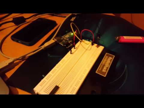
Now all you have to do is upload the code to the Arduino and watch the onboard LED!
I used a small lighter to activate the sensor.
I currently have a YouTube video uploading that demonstrates the project!
I will try to edit this once the video has uploaded. You should be able to do a search for:
"Arduino Uno - Flame Sensor"
Thank you for reading this, and I hope it helped!