Arduino Traffic Light Circuit
by HenriqueT11 in Circuits > Arduino
959 Views, 1 Favorites, 0 Comments
Arduino Traffic Light Circuit
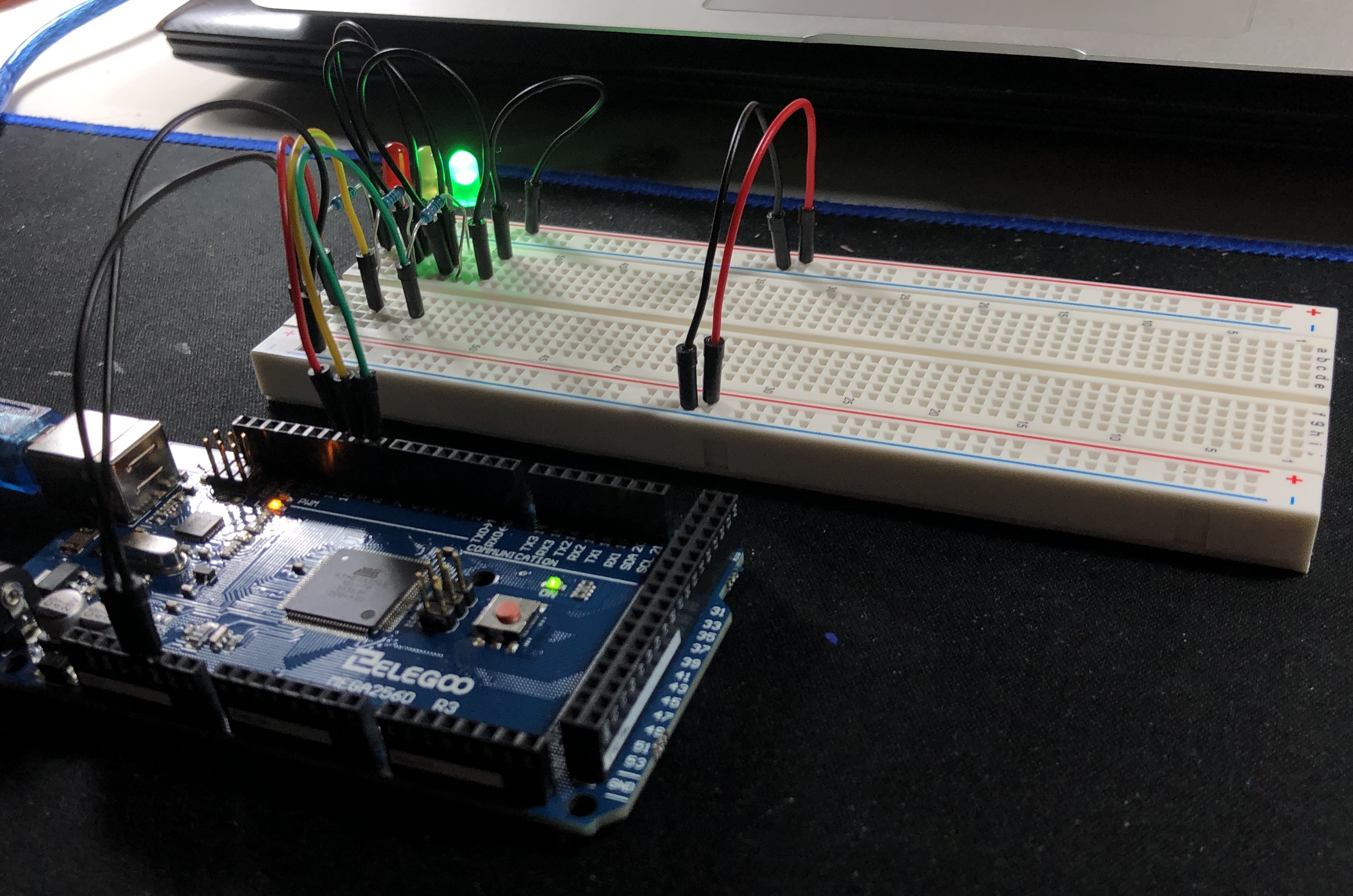
Ever since I remember, I have always been fascinated with technology and automation that used all around of us. One of the most interesting pieces of automated technology, and one of the most vital to safety, is the traffic light. It always amazed me how such a thing could be possible, every couple of minutes a device tells a driver whether to go, slow down, or stop, ultimately making roads infinitely safer. In this Instructable I will be demonstrating how to replicate the circuit behind these essential pieces of technology using an Arduino.
Supplies
- Arduino
- BreadBoard
- 1x Green LEDs
- 1x Yellow LEDs
- 1x Red LEDs
- 3x 220 Ohm Resistor
- Connecting Wires
- USB to Arduino Cable
Gathering and Organizing Supplies
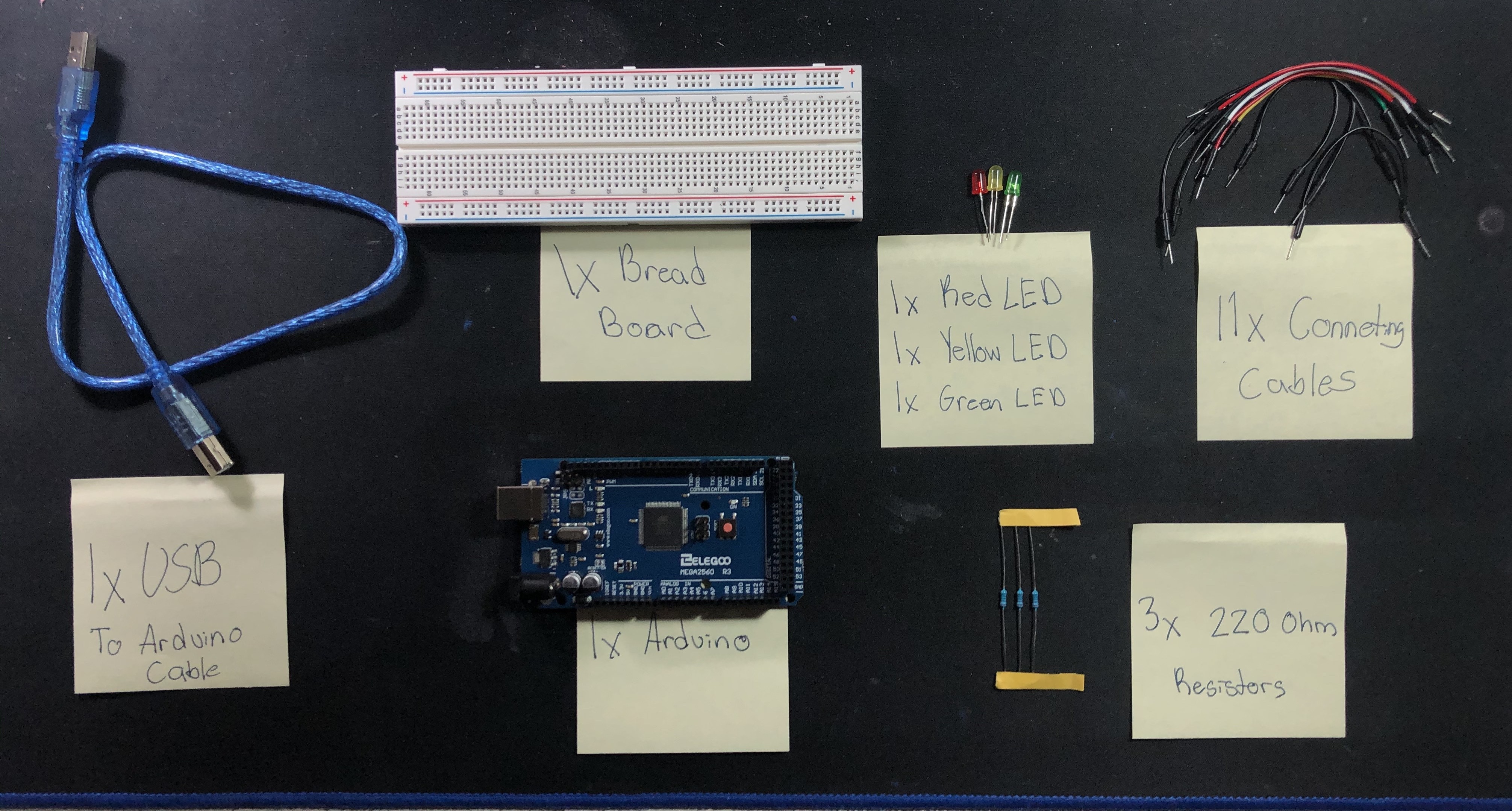
In this first step we will be gathering our supplies and organizing them to make the entire process faster and easier. As mentioned before these will be the necessary supplies:
- Arduino
- BreadBoard
- 1x Green LED
- 1x Yellow LED
- 1x Red LED
- 3x 220 Ohm Resistor
- 11x Connecting Wires
- USB to Arduino Cable
Setting Up the Traffic Light Circuit
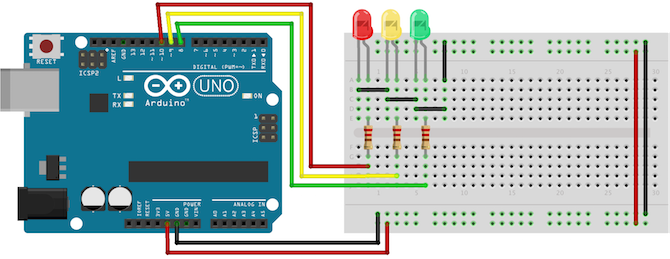
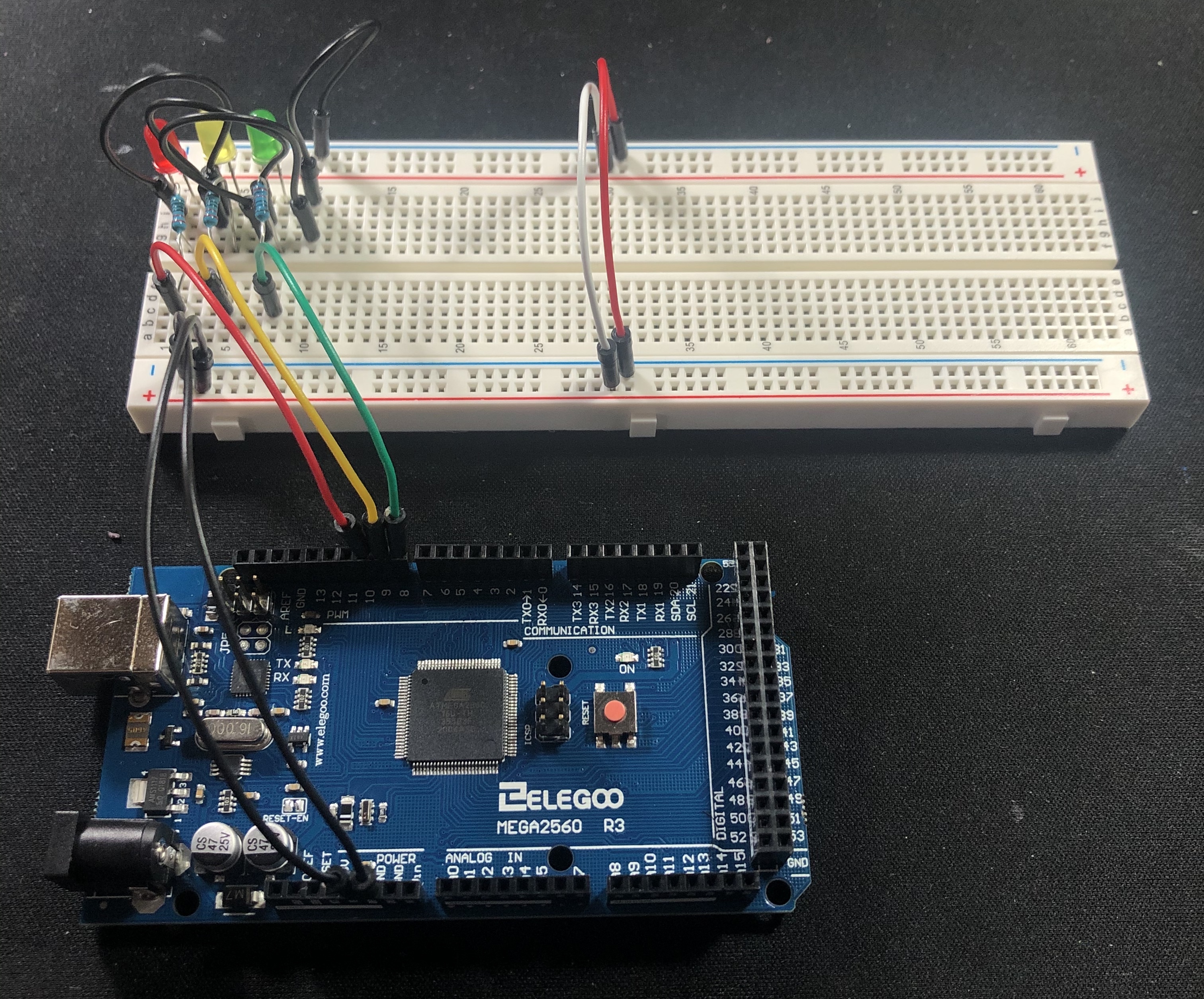
Now that our supplies are set up and organized we can begin the first circuit. Replicate the circuit shown in the attached image. Once the circuit is complete, we must program it to function like a traffic light. To do so, one must download the Arduino IDE, where all of the coding will be done (Arduino IDE Download, this link will direct you to page where you can install the Arduino to your corresponding operating system). Now that all the proper set up is complete we can begin to program our traffic light.
Writing the Code

Hopefully you will notice that each colored LED is connected to a corresponding pin on the Arduino, 10 for red, 9 for yellow, and 8 for green. When coding, rather than using the pin number we can just use the color of the LED. This can be done with these three lines of code:
int red = 10
int yellow = 9
int green = 8
Writing the Code (continued)
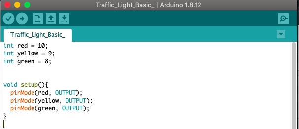
Now we will set up each LED as an output. This is done with these lines of code:
void setup() {
pinMode(red, OUTPUT);
pinMode(yellow, OUTPUT);
pinMode(green, OUTPUT);
}
See how each of the LEDs is referred to via color rather than a number (this is done for clarity), this is possible because of the previous step.
Writing the Code (continued)
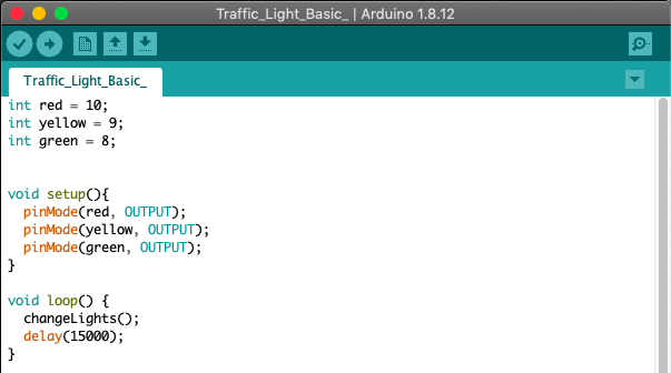
Before we can begin coding the Arduino to alternate between the LEDs we set as outputs, we have to create a loop that will operate every 15 seconds . The string of code is as follows:
void loop(){
changeLights();
delay(15000);
}
Note: 1000 = 1 second, hence 15000 = 15 seconds
Writing the Code (continued)
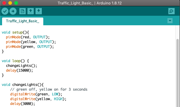
Next we will create the alternating pattern of illumination for each of the LEDs, this is the first:
void changeLights(){
// green off, yellow on for 3 seconds
digitalWrite(green, LOW);
digitalWrite(yellow, HIGH);
delay(3000);
(Note that when coding that whenever, //, is used it is only a note for the coder, this means all the text following it on that row will not change any function on the Arduino, in this case is it simply there to understand what the corresponding string of code is doing)
This string of code will allow the Arduino to switch from, on a traffic light, green to yellow, or switching from "GO" to "SLOW DOWN."
Writing the Code (continued)
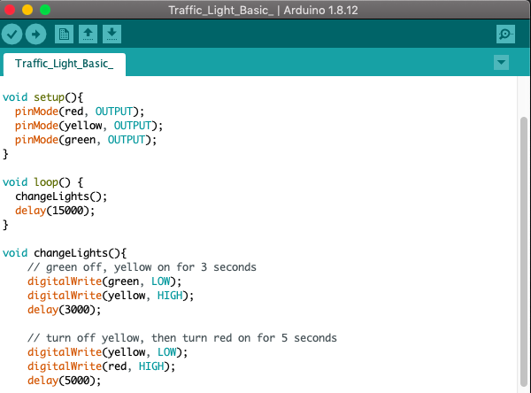
Continuing the alternating pattern of illumination:
// turn off yellow, then turn red on for 5 seconds
digitalWrite(yellow, LOW);
digitalWrite(red, HIGH);
delay(5000);
This will act as switching from "SLOW DOWN" to "STOP," or on a traffic light switching from yellow to red.
Writing the Code (continued)
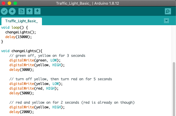
Continuing the alternating pattern of illumination:
// red and yellow on for 2 seconds (red is already on though)
digitalWrite(yellow, HIGH);
delay(2000);
This will act as the transition period between red and green on a traffic light, or the period between "STOP" and "GO."
Writing the Code (final)
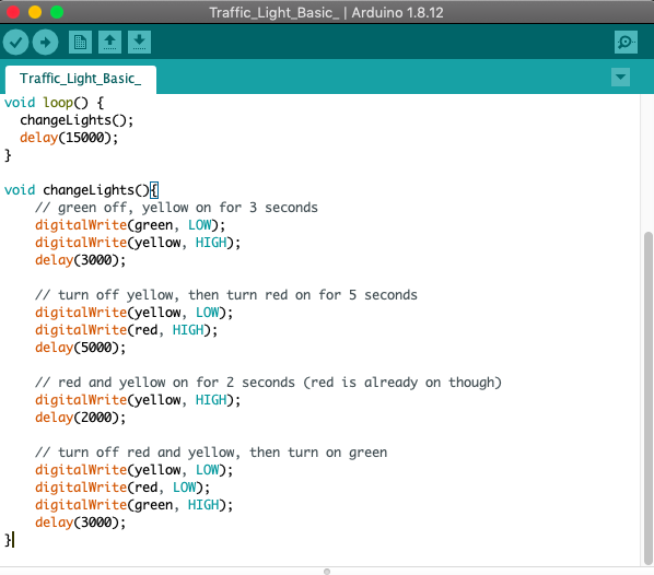
Concluding the alternating pattern of illumination:
// turn off red and yellow, then turn on green
digitalWrite(yellow, LOW);
digitalWrite(red, LOW);
digitalWrite(green, HIGH);
delay(3000);
}
This will act as the first stage of the 15 second cycle, the traffic light begins on green, "GO."
Verifying the Code

Now that the code is complete we must verify that it was written properly. To do so all you must do is click the check mark in the top right hand corner of the software. Once the verify button is clicked, all the code will be compiled, and if it is written properly the message "Done Compiling" will appear at the text box found at the bottom of the software.
Uploading Code to Arduino
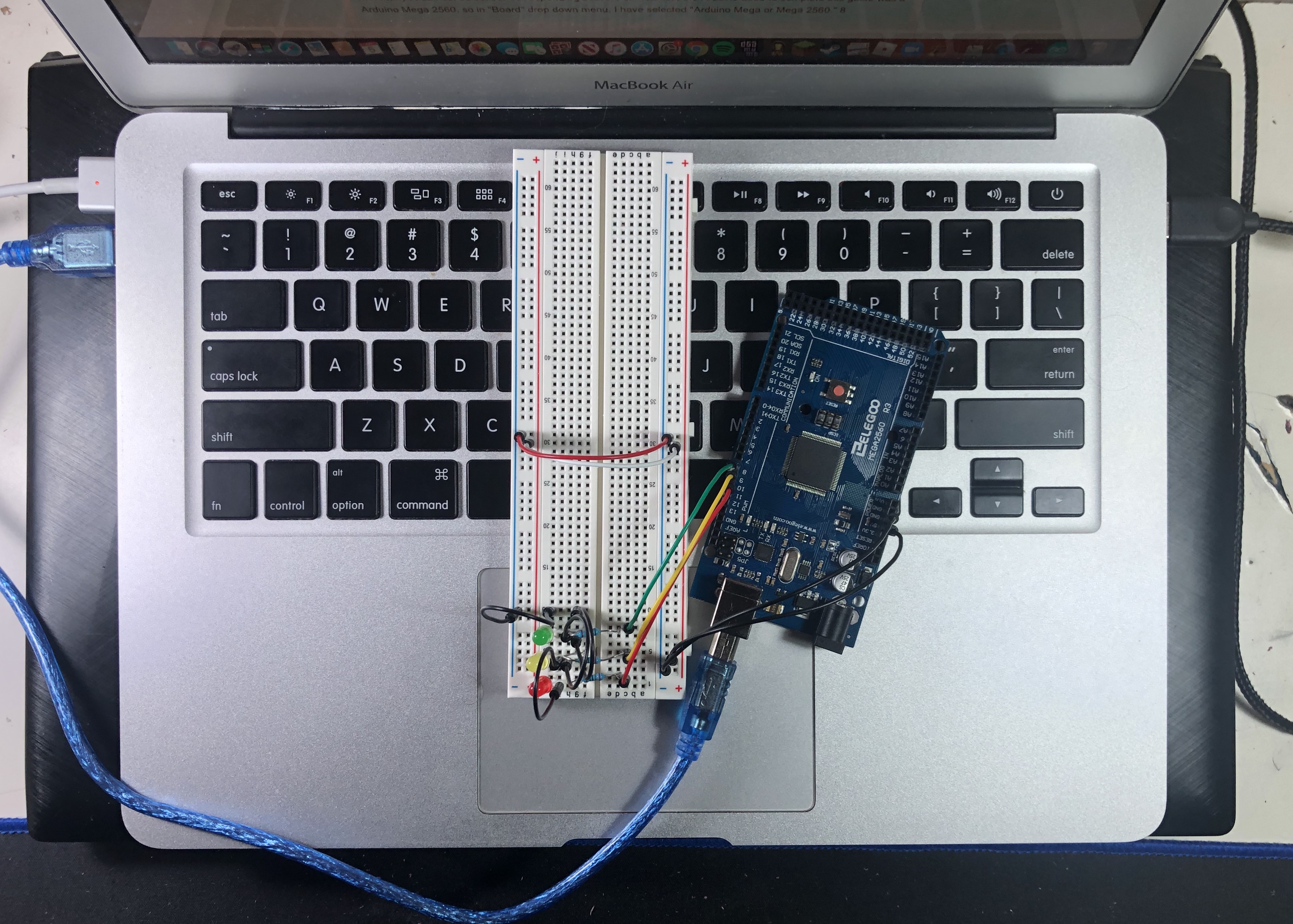
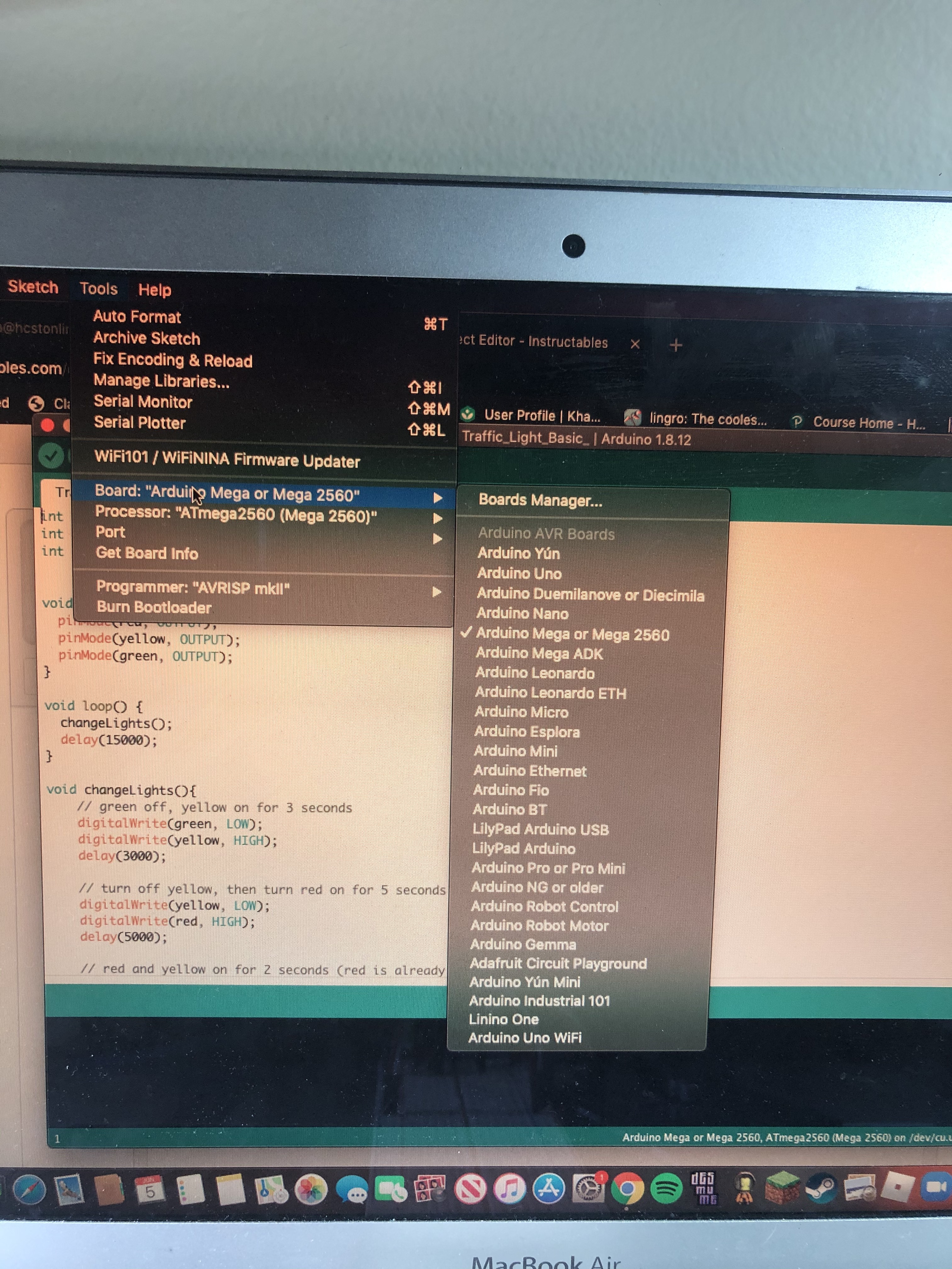
The final step before our traffic light circuit is finally complete, we have to connect our Arduino to the computer we have written the code on. Connect the USB end into one of the USB-ports of the computer, and the other end into the Arduino. Once this is complete we must make sure the Arduino IDE software is set up properly with your Arduino. This can be done by going into the "Tools" tab, from here select "Board," now a drop menu will appear with many Arduinos, select our corresponding board. For instance, the Arduino used to complete this guide was a Arduino Mega 2560, so in "Board" drop down menu, I have selected "Arduino Mega or Mega 2560." Now that everything is complete, you should a fully functional Arduino Traffic Light!