Arduino Timer for Writing Homework
by YuTingHsu0225 in Circuits > Arduino
204 Views, 1 Favorites, 0 Comments
Arduino Timer for Writing Homework
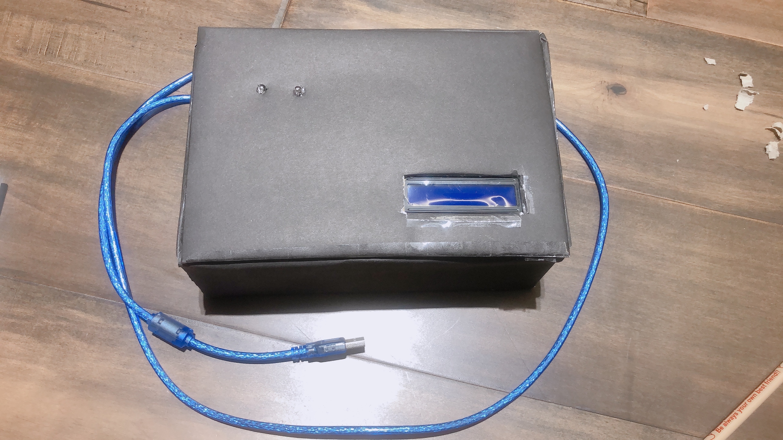
In this tutorial, you will learn how to build an Arduino timer for young age students to write their homework effectively. The timer will start once it is plugged on, and the timmer has two main sections which includes the working time and the break time after. The code provides here made the working time for 10 minutes, nad breaktime for 5 minutes, obviously, you can change the length of time if you want to. This tutorial includes the materials, steps, and the code needed to build this machine. This machine is simple and easy but a lot of fun even for Arduino beginners. So...... Let's start!
*The LCD used in this machine requires a library, so download it while you download the code. The link of the library is provided in the code.
Materials
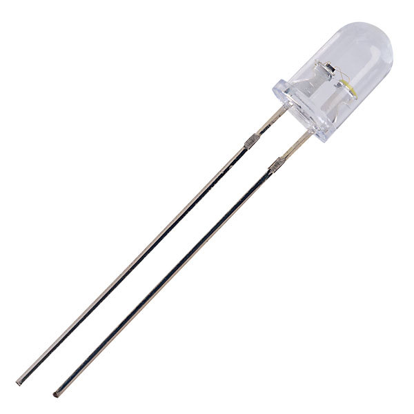
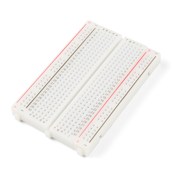
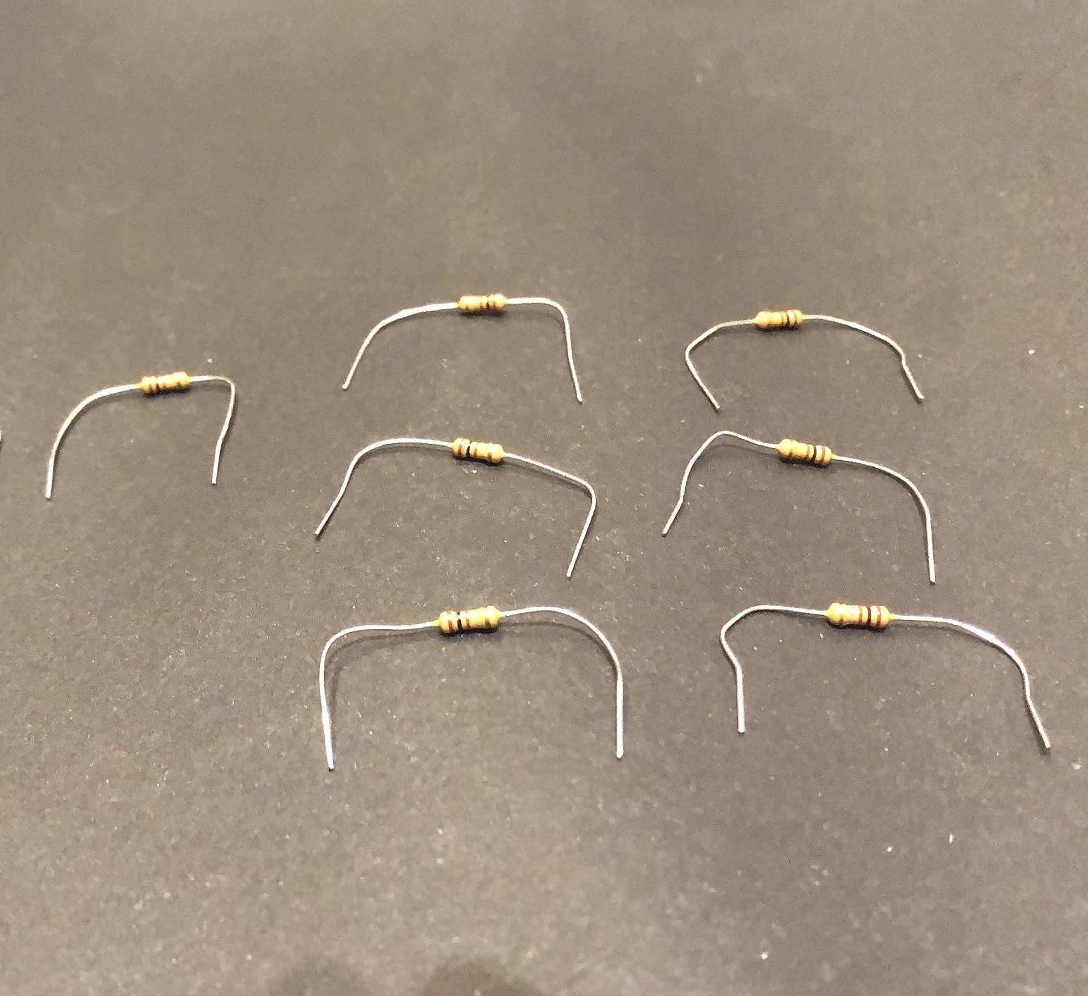
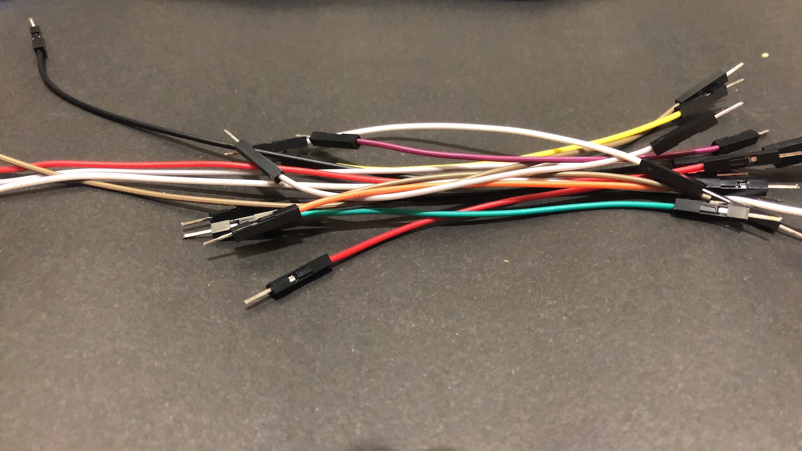
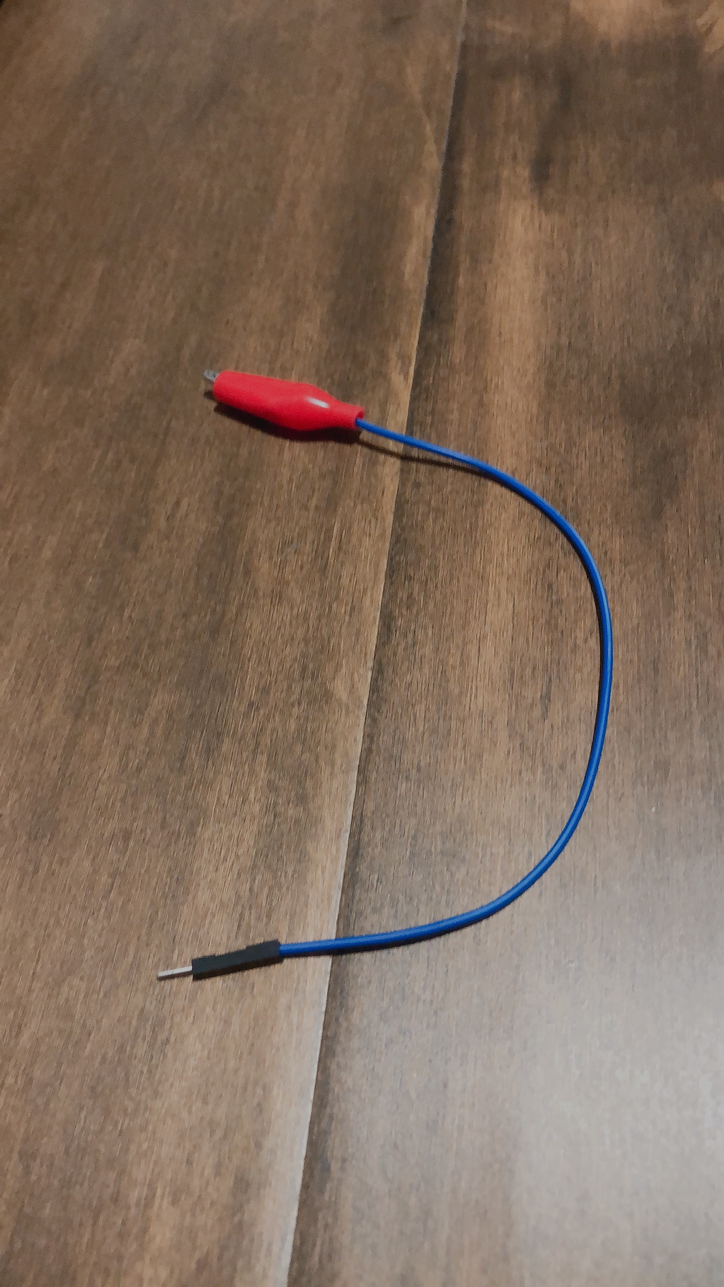
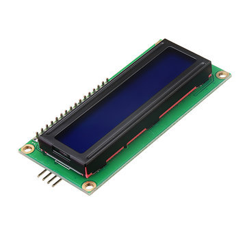
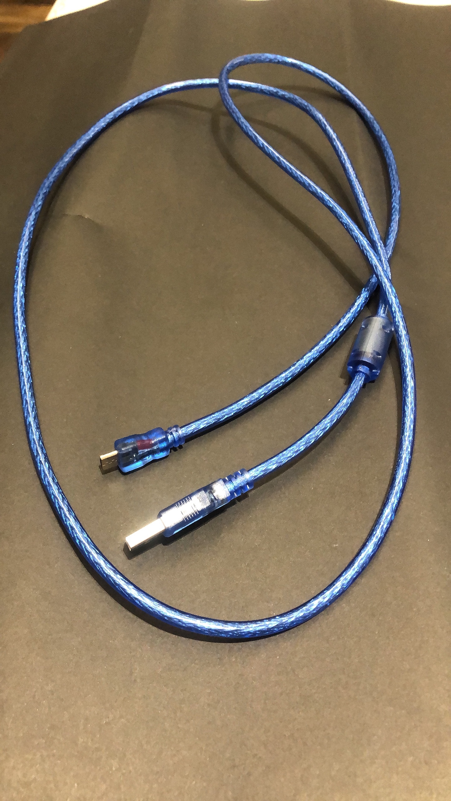
Before you start to build this machine, you will need to prepare all the materials needed so your machine can work well since you didn't miss any steps or lost any components and parts while building. The materials needed to build this machine is listed below:
- Two LEDs
- Red x1
- Green x1
- Breadboard
- Arduino Leonardo
- Two resistors
- Wires
- Crocodile clip
- LCD
https://www.aliexpress.com/item/4000073836219.html
- Arduino Software
- USB cord
- Laptop
- Cardboard
- Colored paper
Attach LCD to Arduino

After you got all materials needed, connect LCD to your Arduino. The LCD should be attached to four specific pins on the Arduino board. The SCL and SDA should connect to the SCL and SDA pin on the left of the Arduino board, and VCC should be connected to 5v and GND to GND on the Arduino. Be careful when connecting the LCD to Arduino, the Lcd might broken if the pins are not connected correctly. The image above gives you a sample picture of how I plug it onto my Arduino. (You will not need the breadboard in this step.)
Attach LEDs to Breadboard

Second, attach all LEDs to your breadboard. The picture here is a sample of how you can connect your LEDs to your breadboard. The red LED should be connected to the D6 pin and the green LED should be connected to the D7 pin in order to keep the order correct. *Remember to connect one resistor to each LED, and then connect them back to GND on Arduino.* (This is the part where you need your breadboard.)
Create the Exterior of Your Machine
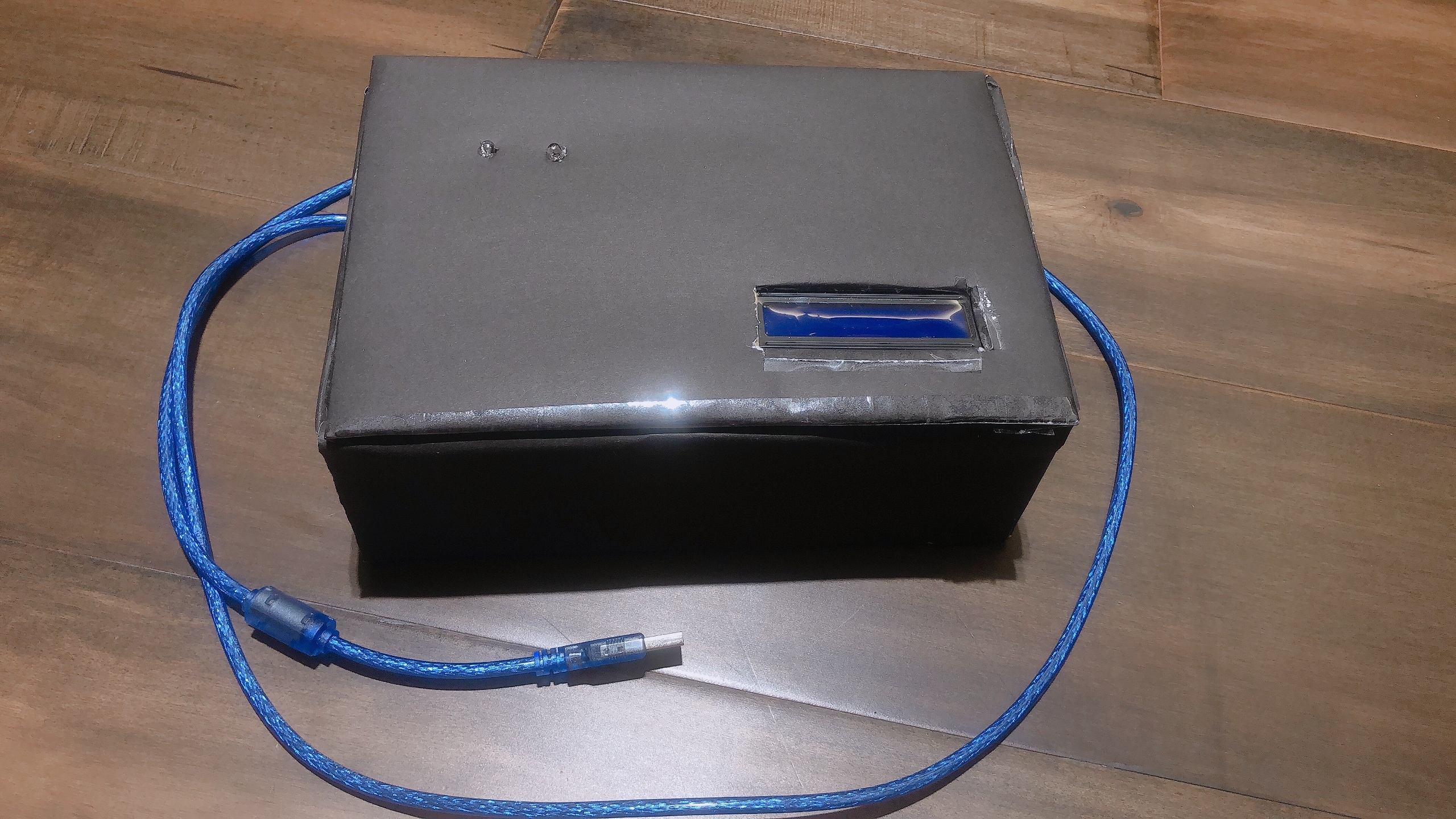
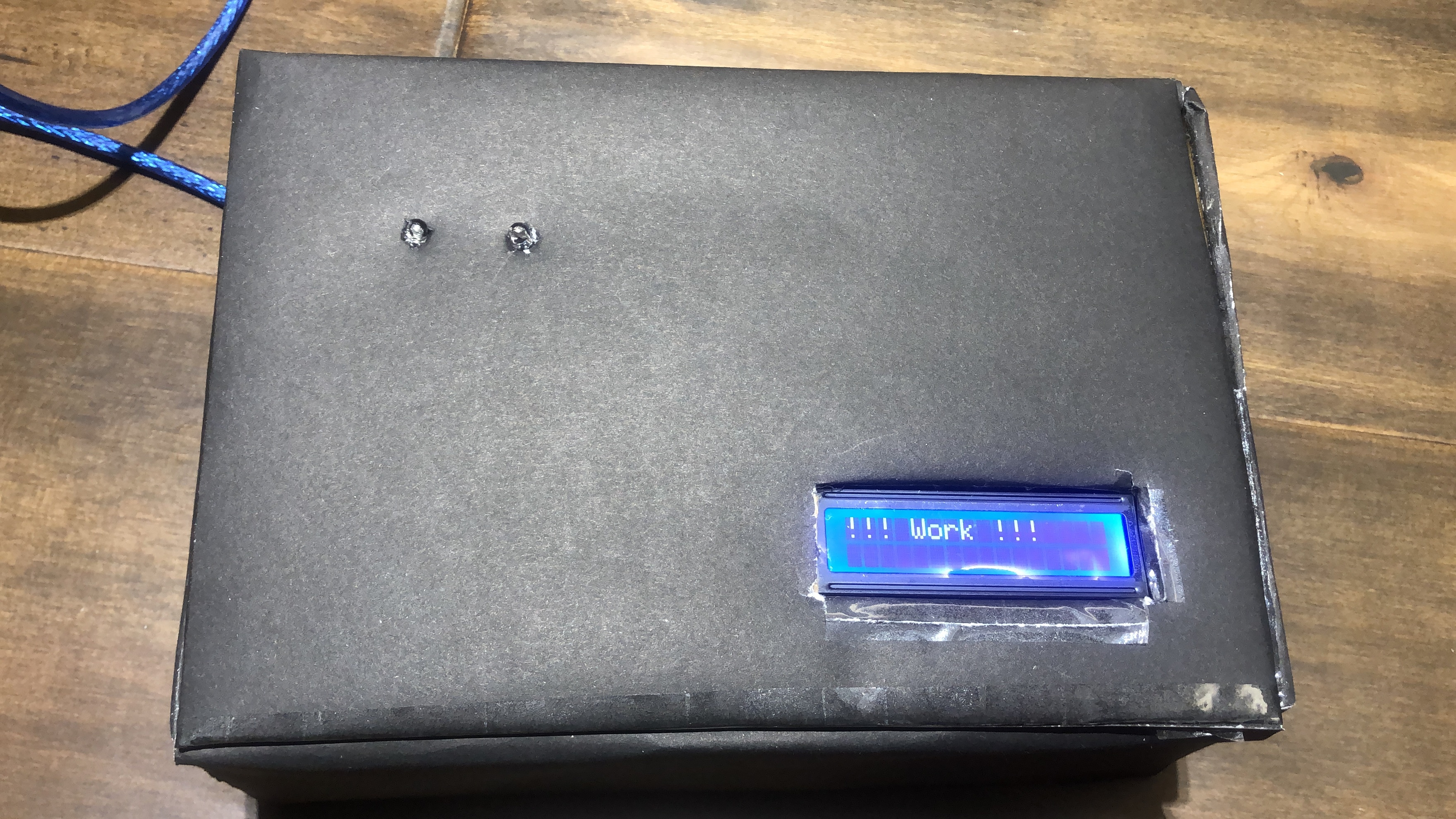
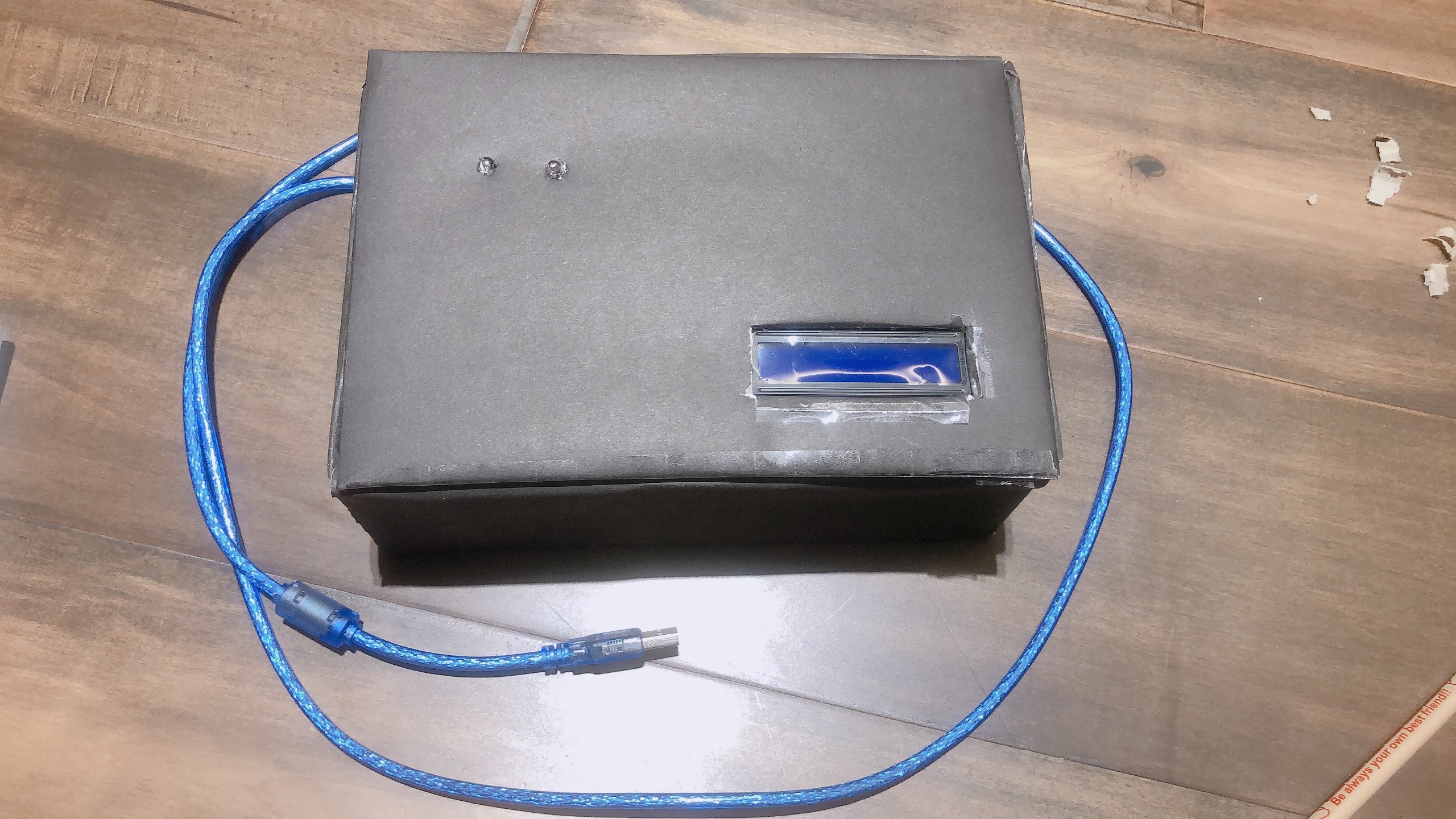
Now, use your imagination and creativity to create a cover of your machine. You can use any material you want if you want to make a special and creative one. If not, here is a sample of how I cover my machine. I use cardboard and paper to wrap up my machine.
Pull Your LCD and LEDs Out
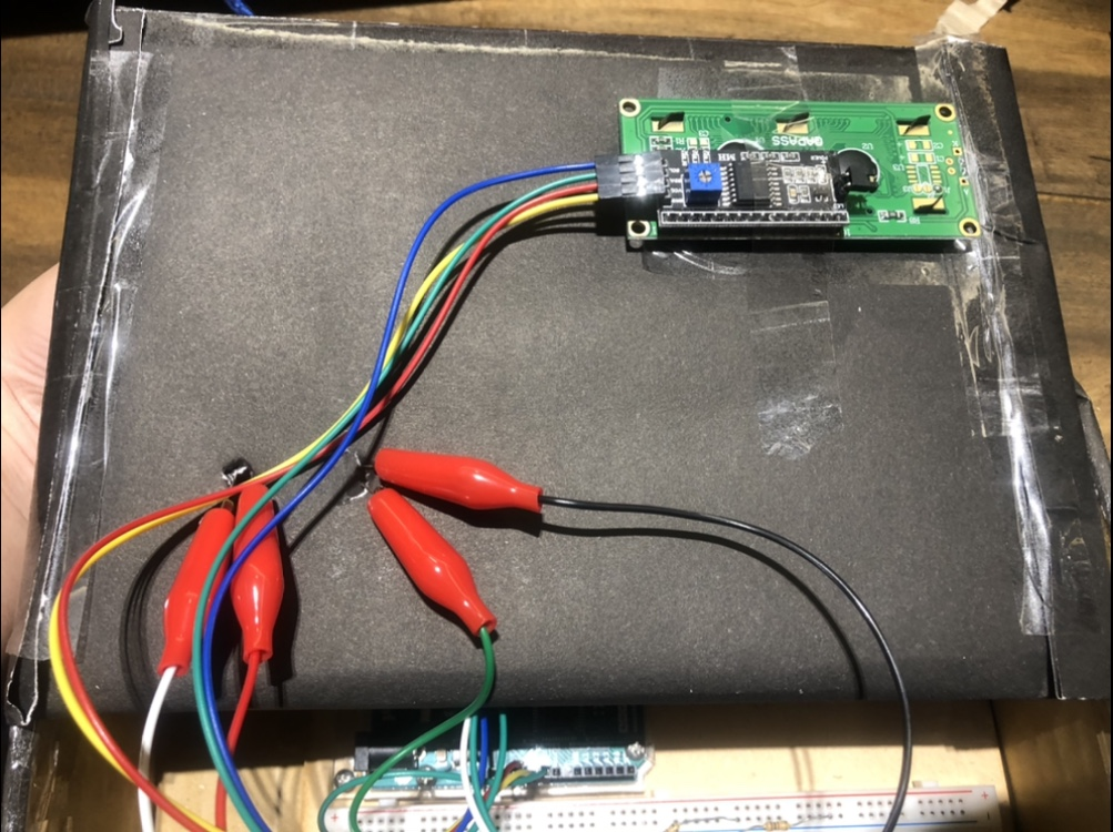
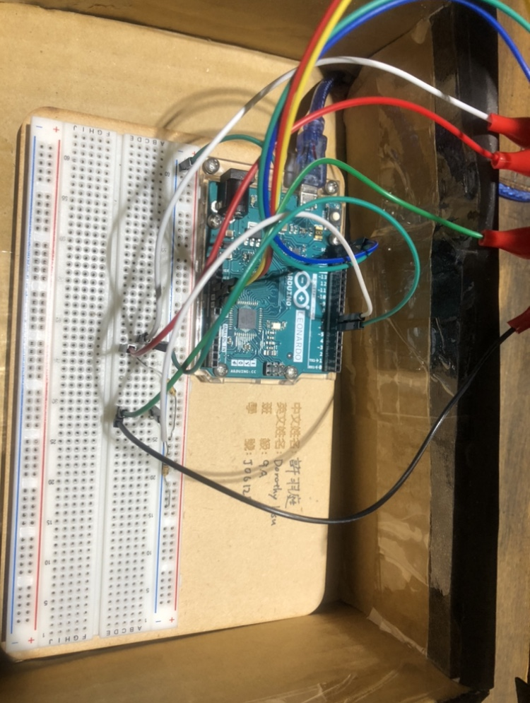
Next, after you finish making your cover, remember to pull out your LEDs and LCD, so your Arduino machine can still work even if you need the breadboard and most of the wires under the cover. You may need some extra wires or crocodile clips to keep the LEDs connected to the breadboard. Only stick the LEDs and LCD out the cover to make the machine looks better.
Code
Finally, after finishing all the attaching, input the Arduino code for this machine.
Here is the code of this timmer, you can copy and past it to your Arduino software.
Finish!!
.JPG)
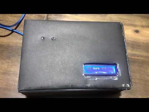
Finally, this Arduino timmer should be done now. If you feel this project has any section or part that should be changed or can improve, welcome to improve it and comment here to make it better.