Arduino Temperature Sensor With LCD
by RayTechnologies in Circuits > Assistive Tech
5363 Views, 8 Favorites, 0 Comments
Arduino Temperature Sensor With LCD

Hello everyone! We are a newly created company, Ray Technologies. We're a team of engineers, programmers, and more. Currently, we are playing with different technologies like, Raspberry Pi, and Arduino. So furthermore, today we are going to demonstrate how to make an "Arduino Temperature Sensor With LCD".
Parts List
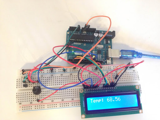
Hardware:
1 - 1x Arduino UNO board
2 - 1x LCD Display
3 - 1x 220Ω Resistor
4 - 1x 10k Potentiometer
5 - 1x TMP36 Temperature Sensor
6 - (A lot of) Jumper Wires
7 - 1x Breadboard
8 - 1x Cord for connecting to your Arduino
Software:
1 - Arduino IDE
2 - LiquidCrystal Library for Arduino
LCD Display
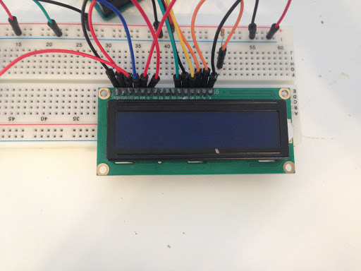
Okay, so you can now mount the LCD Display wherever you would like, on the breadboard. (Just not on the power rails, obviously.)
Note: for the LCD display you will need 12 jumper wires.
Before you do the next step, attach a jumper wire from the Arduino 5V pin, to the breadboard positive power rail. Next attach a jumper wire from the Arduino GND pin, to the breadboard negative power rail. You are now ready to go to the next step.
Wiring for the LCD Display
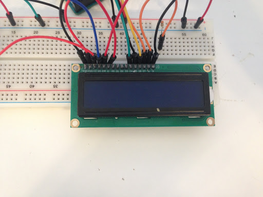
Alright, now for the more "complicated" part: Note the change from "LCD 6" to "LCD 11"
The potentiometer can go wherever you would like on the board.
______________________________________________________________________________________________
LCD 1 to breadboard negative power rail
LCD 2 to breadboard positive power rail
LCD 3 to potentiometer centre pin // this helps to change the LCD brightness
LCD 4 to Arduino Digital Pin 12 // Arduino sends LCD data (LCD character coordinates)
LCD 5 to breadboard negative power rail
LCD 6 to Arduino Digital Pin 11 // Arduino sends LCD data (LCD initiate command)
LCD 11 to Arduino Digital Pin 5 // Arduino sends LCD data
LCD 12 to Arduino Digital Pin 4 // Arduino sends LCD data
LCD 13 to Arduino Digital Pin 3 // Arduino sends LCD data
LCD 14 to Arduino Digital Pin 2 // Arduino sends LCD data
LCD 15 to 220 ohm resistor and then the same 220 ohm resistor to breadboard positive power rail
LCD 16 to breadboard negative power rail
Potentiometer positive pin to breadboard positive power rail
Potentiometer negative pin to breadboard negative power rail
Once you've finished all of that, you can go to Wiring the TMP36 Temperature Sensor.
Wiring for the TMP36 Temperature Sensor
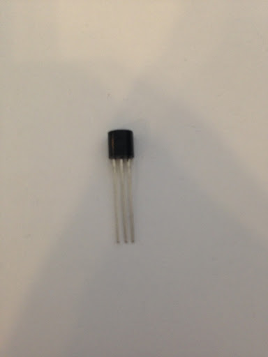
Okay, so we've gathered all of our parts, and we've wired the LCD Display to the breadboard and Arduino. Now we need to add the TMP36 Temperature Sensor. Follow the steps below:
1 - Put the TMP36 onto the breadboard wherever you would like, be sure the flat side is facing away from you. (Again, not on the power rails)
2 - Attach a jumper wire to the middle pin of the TMP36. Attach the same wire to the Arduino "A0" pin.
3 - Attach the positive (right pin) to the positive power rail.
4 - Attach the negative (left pin) to the negative power rail.
After you have completed wiring the TMP36, you can go to the next step!
Programming
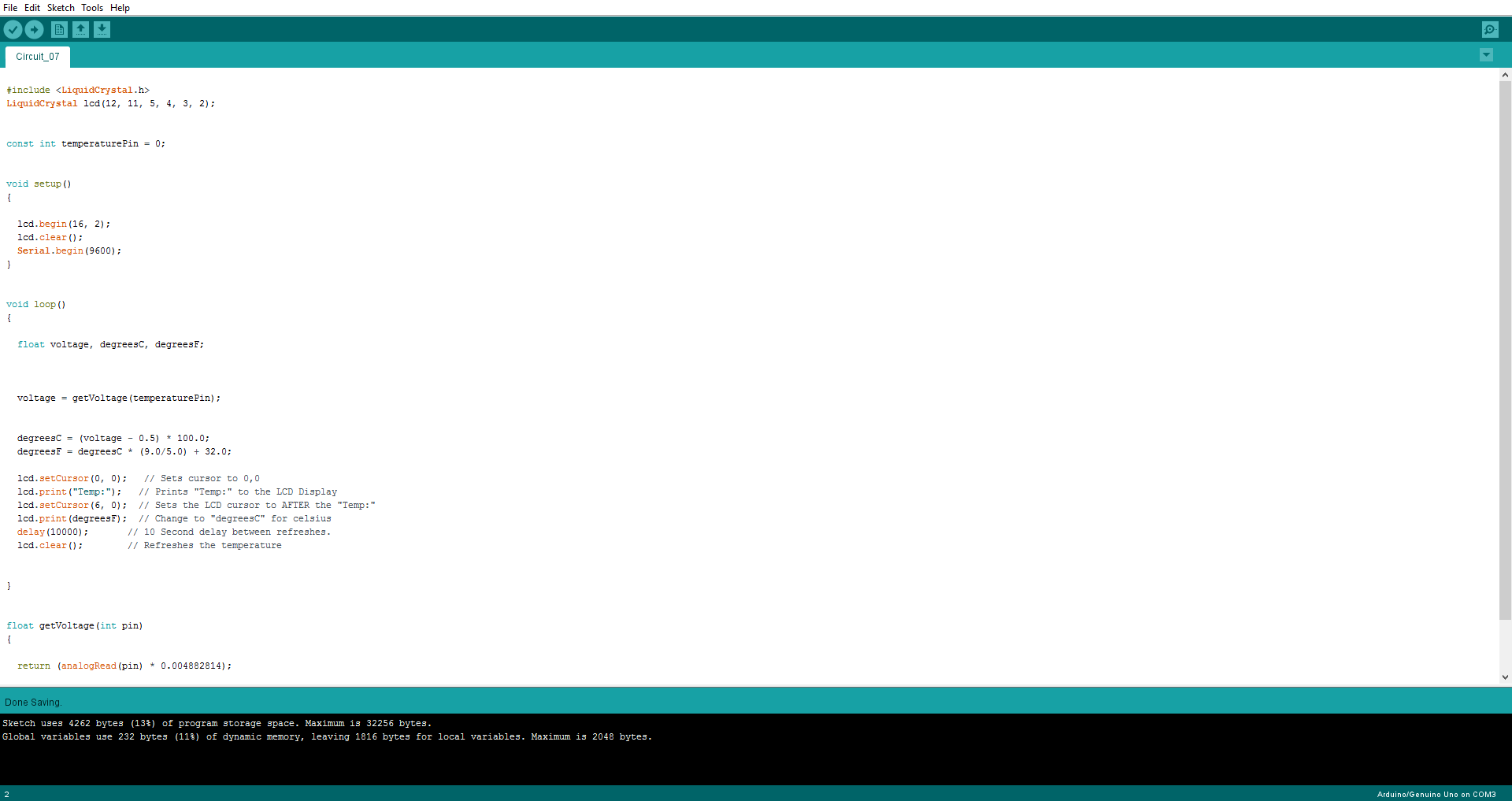
This is probably the easiest step in this Instructable. All you have to do is, download the file, and hit "Upload".OR, you could program it on your own. Your choice really. But anyways, I wrote the code for anyone who wants to use it.
Downloads
Test!
Alright. So after you upload the code, the LCD Display should light up, and say something like "Temp: 72.5". If it does, congratulations! You have just made an Arduino Temperature Sensor with LCD! If it doesn't work, double-check the wiring, and code.
Thanks for taking the time to read this Instructable!
~ Ray Technologies