Arduino-Teensy4 for Teensy 4.0 - Full Assembly
by cburgess129 in Circuits > Arduino
4422 Views, 1 Favorites, 0 Comments
Arduino-Teensy4 for Teensy 4.0 - Full Assembly
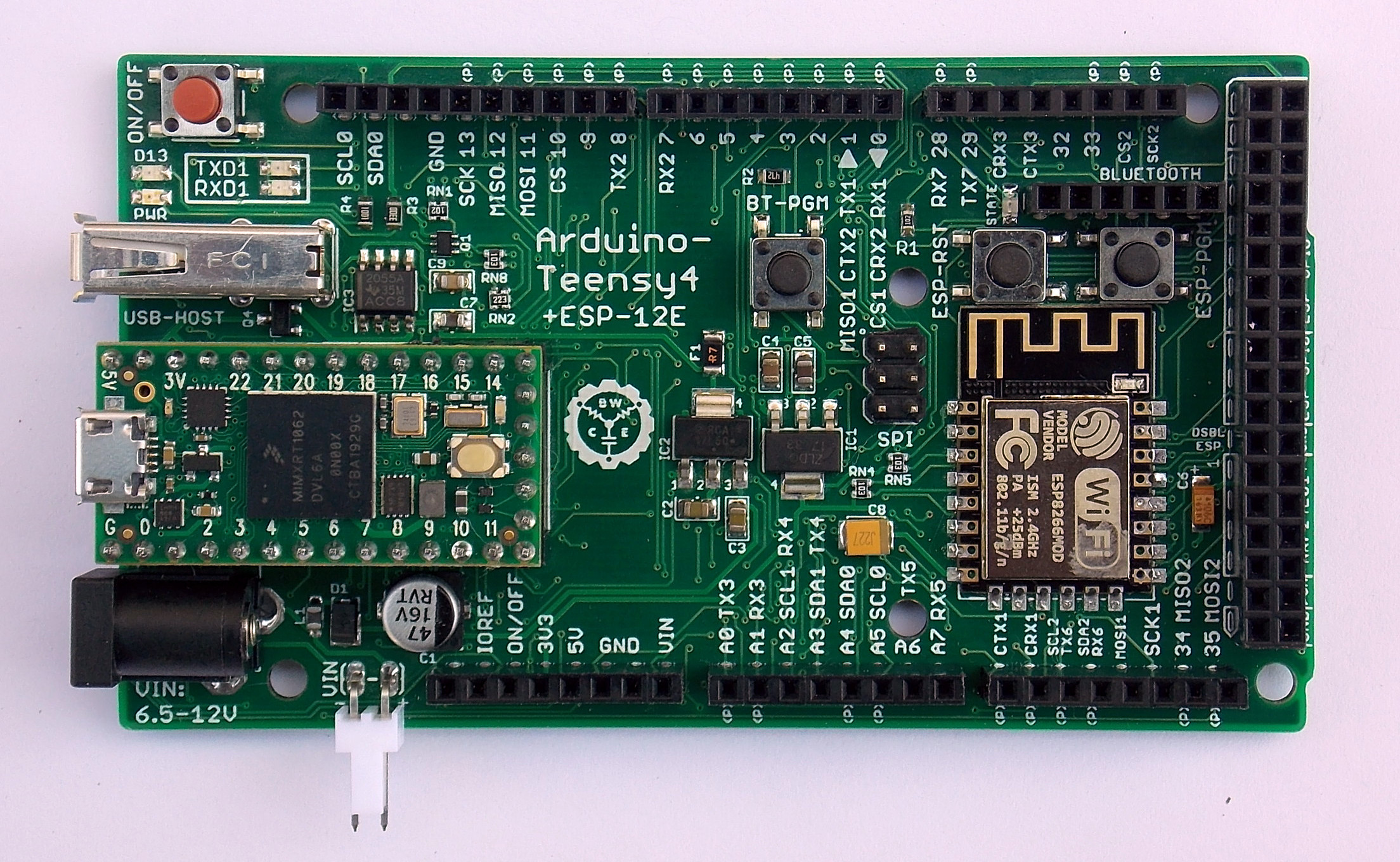
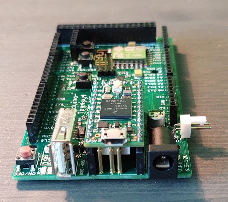
This instructable will walk you through the assembly of the Arduino-Teensy4 expansion board for Teensy 4.0
You can purchase one from my Tindie store here:
https://www.tindie.com/products/cburgess129/arduin...
You can order a Teensy 4 along with your board or order one from PJRC here:
Component List
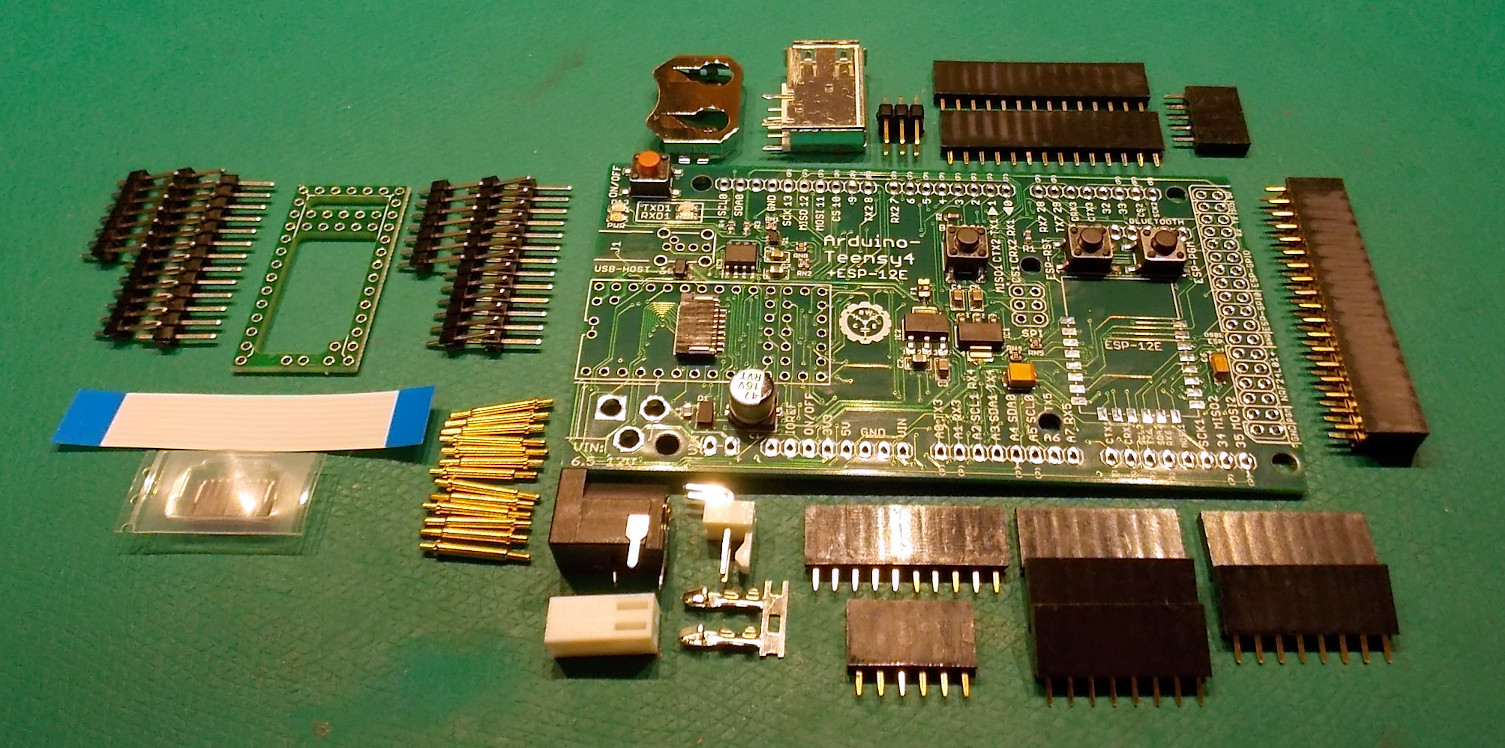
This is the list of parts that come with the Arduino-Teensy4 expansion board:
- Arduino-Teensy4 PCB with SMD components installed
- POGO pin alignment tool with male headers
- (1) 10-pin female header
- (5) 8-pin female headers
- (2) 13-pin female headers
- (1) 6-pin female header
- (1) 7-pin female header
- (1) 38-pin female header
- (1) 1 2x3 pin male header
- Male header pins for Teensy
- 8-pin flatflex cable
- (13) 12.5mm POGO pins
- (1) 8-pin flatflex connector for Teensy
- (1) 2.1mm barrel jack
- (1) 2-pin male MOLEX connector
- (1) 2-pin female MOLEX connector
- (2) pins for MOLEX connector
- (1) SMD 2032 battery holder
- (1) 90-degree USB-A connector
Replacement flatflex cables and connectors can be purchased from my Tindie shop:
Step 1: Adding Headers
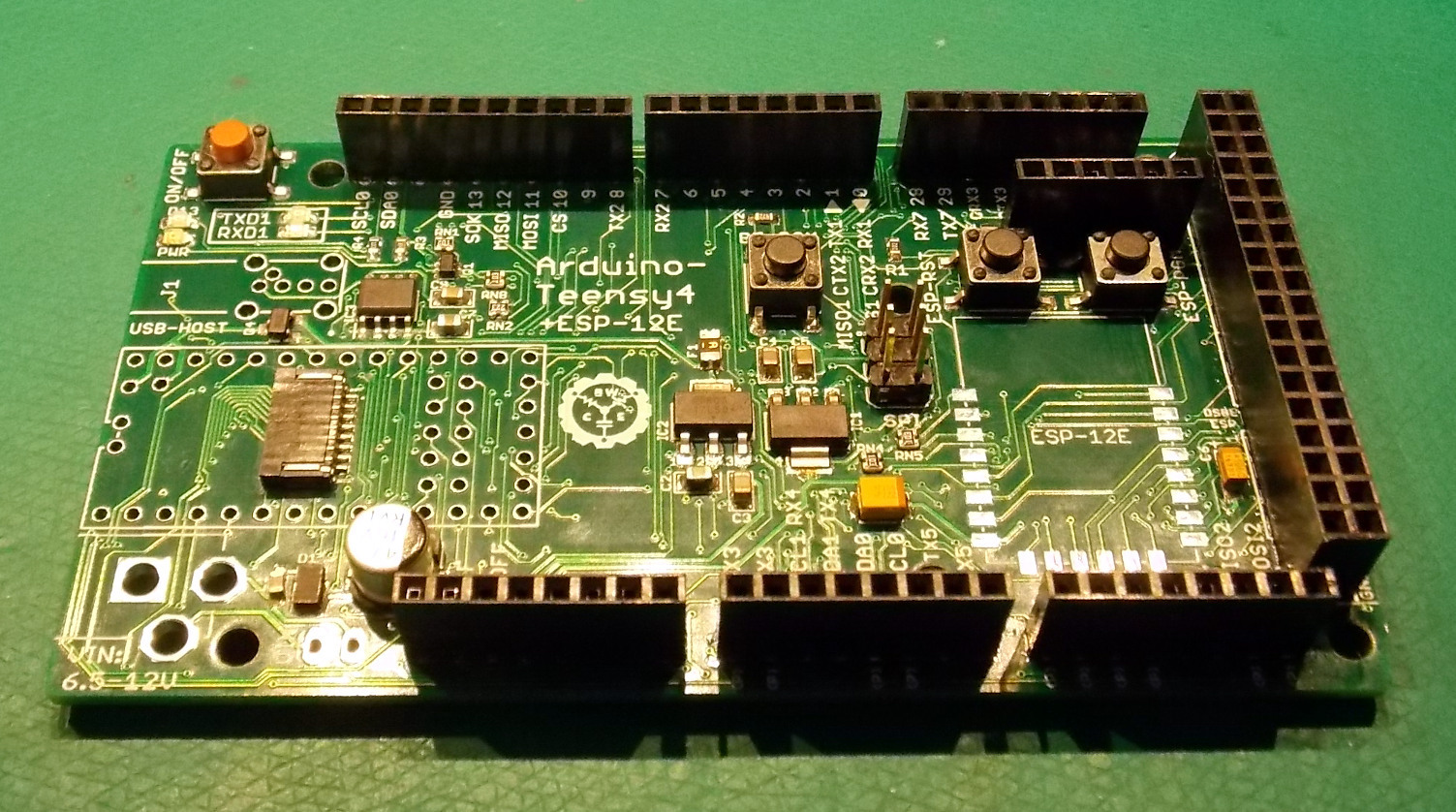
The bare board will come with all of the surface-mount components pre-installed, except for the flatflex connector on the bottom of the Teensy 4 - you will need to install that yourself.
First we will add all of the headers around the perimeter of the board, the 6-pin SPI connector, and the Bluetooth header.
Assembling the Pogo-pin Alignment Tool
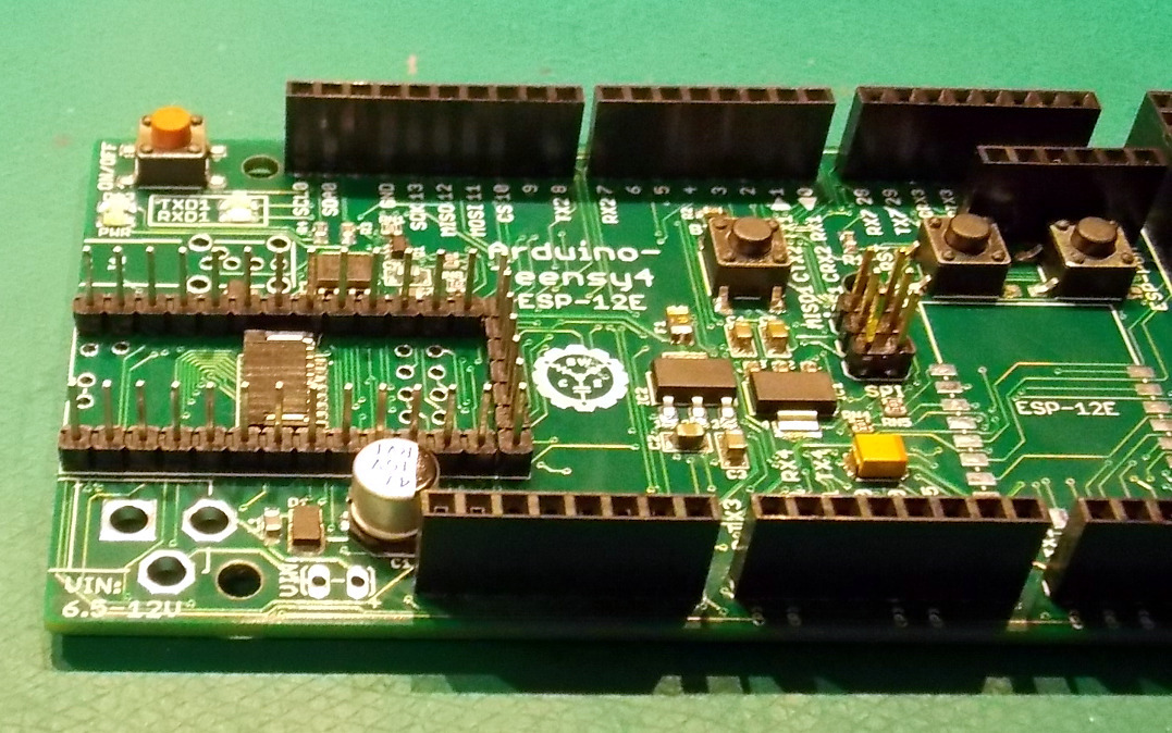
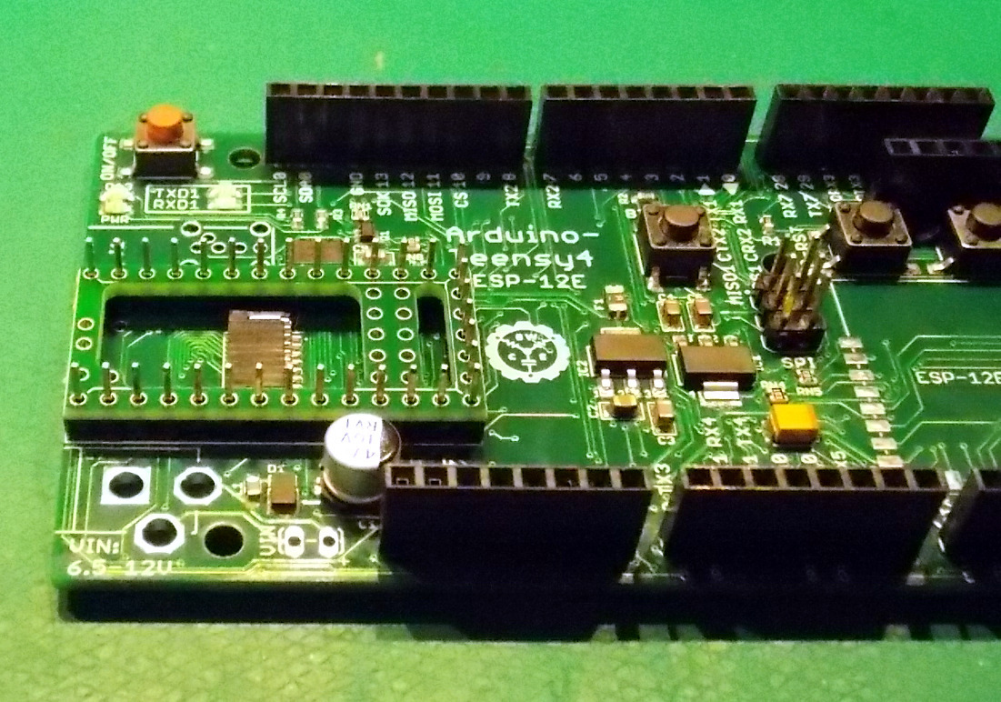
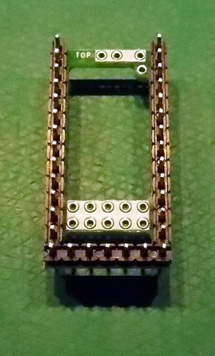
Place the alignment tool male headers into the holes for the Teensy on the main PCB SHORT-SIDE DOWN. This will hold them steady and aligned while you solder them to the alignment tool.
Place the alignment tool UPSIDE DOWN on the male pins - the top of the alignment tool has a white silkscreen and the word "top" printed on it. Solder the pins from the bottom of the alignment tool - DO NOT SOLDER THE PINS TO THE MAIN PCB.
Remove the completed alignment tool from the main PCB. The black strips on the headers should rest on TOP of the alignment tool with the long ends of the pins protruding out the bottom.
Add Female Headers to Support Teensy
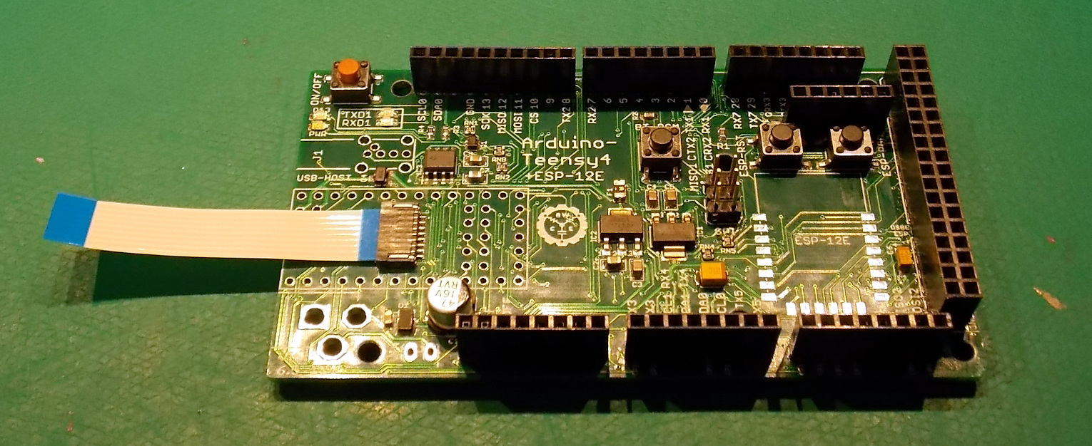
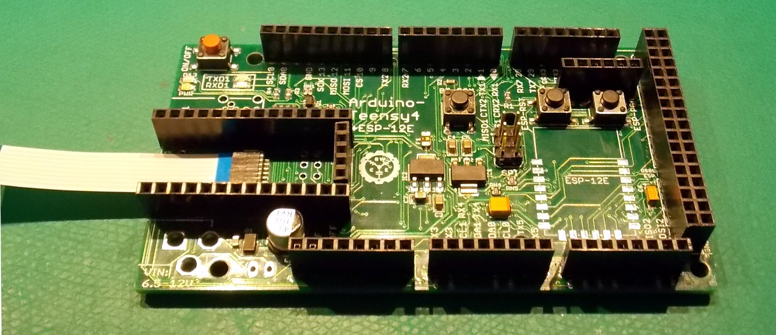
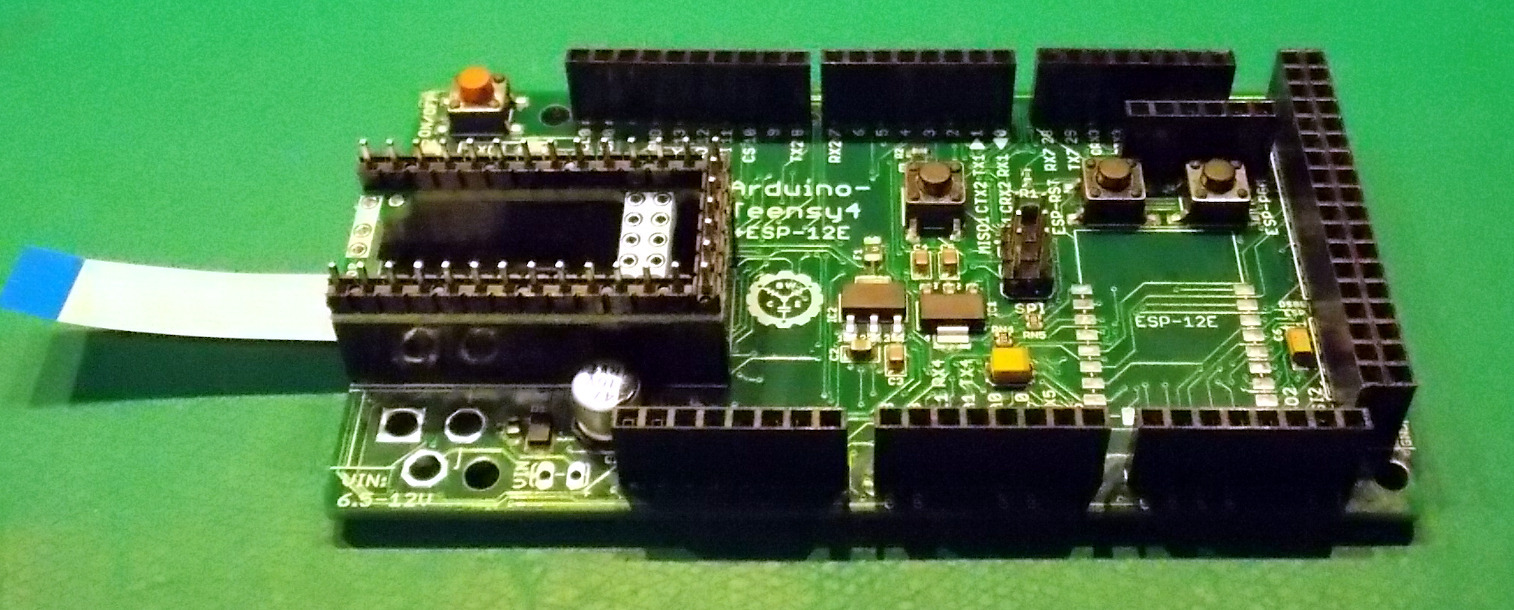
Insert one end of the flatflex cable into the connector on the main PCB. This will be harder to do after the headers are soldered around it.
Insert the female headers into the holes for the Teensy on the main PCB and plug the pogo-pin alignment tool into the top of the female headers. This will stabilize them and keep them aligned during assembly.
Holding the headers in place, turn the PCB over and solder the female headers from the bottom of the main PCB.
Remove the pogo pin alignment tool.
Install POGO Pins
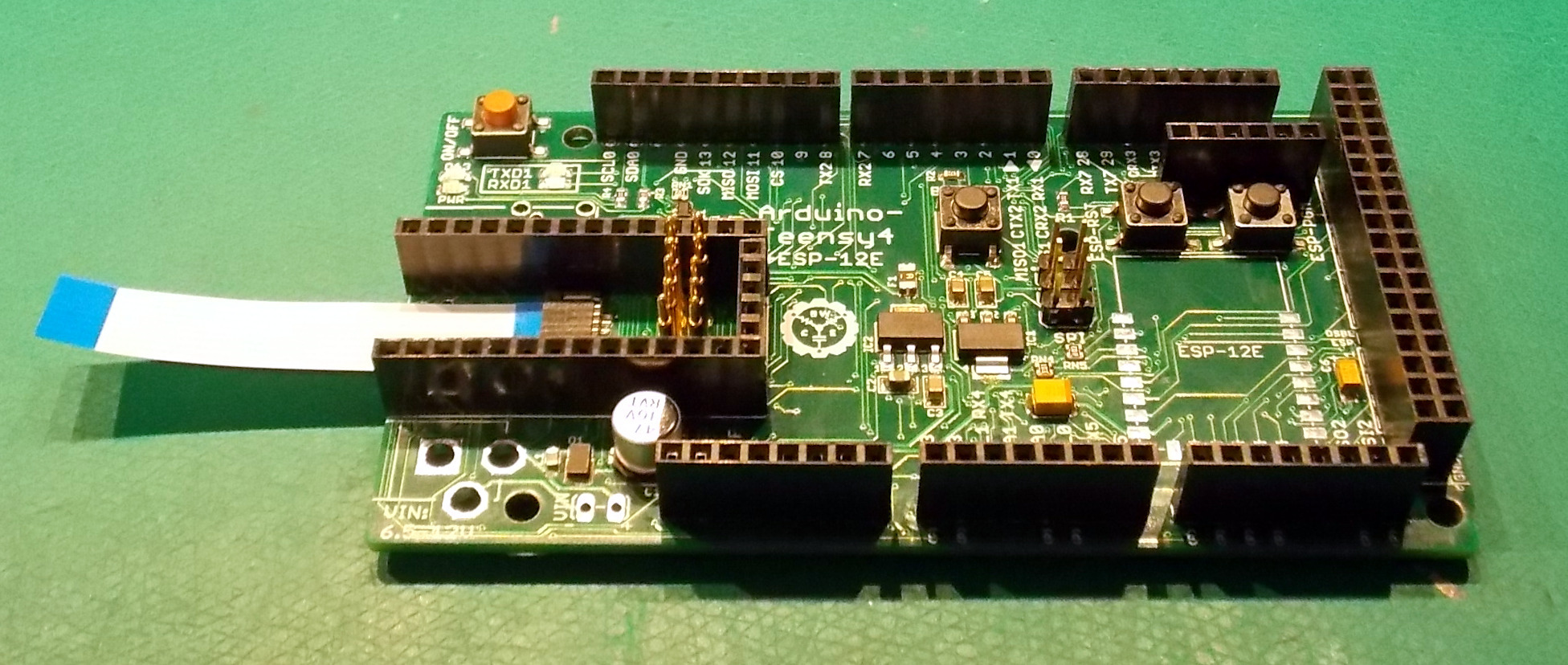
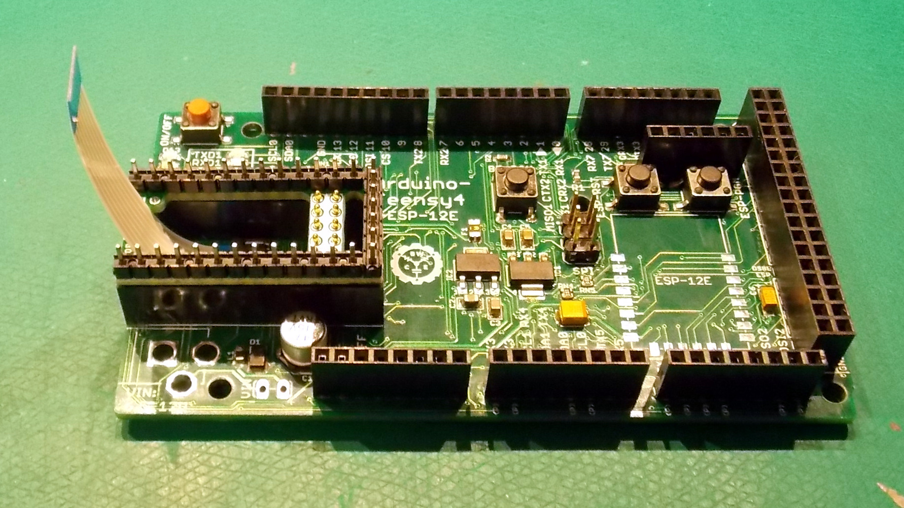
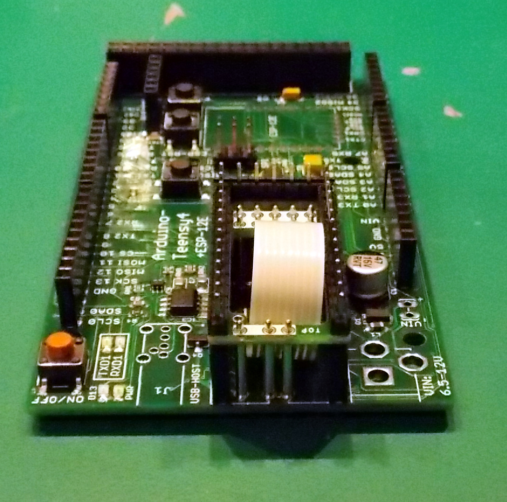
With the alignment tool removed and the flatflex cable installed, drop the 10 rear pogo pins into the holes on the main PCB. Make sure they are standing up straight with their spring ends pointing up.
Install the alignment tool into the female headers and use a thin instrument to align the pogo pins until the spring-end pops through the holes in the alignment tool.
Feed the flatflex cable through the large hole in the middle of the alignment too.
Lift the leading edge of the alignment tool and slide the remaining 3 pogo pins in place. making sure they are seated in the main PCB and their spring-ends are aligned in the holes in the alignment tool.
Seat the alignment tool firmly place and turn the main PCB upside down and solder all of the pogo pins in place.
To make removal of the microSD card easier, you can use some solder wick to remove any excess solder from the bottom of the main PCB over the 3 front-most pins.
Remove the alignment tool and retain to protect the socket and pogo pins when the Teensy is not installed in the main PCB.
Install Flatflex Connector Onto the Bottom of the Teensy
Use solder paste and a hot air rework station, or rolled solder and a soldering iron to install the flatflex connector onto the bottom of the Teensy. Ensure all pins are soldered and there are no solder bridges.
Install Male Headers Into Teensy
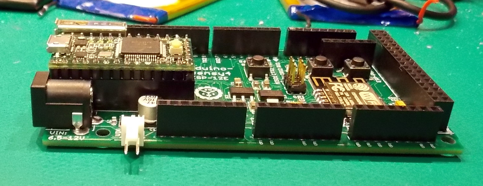
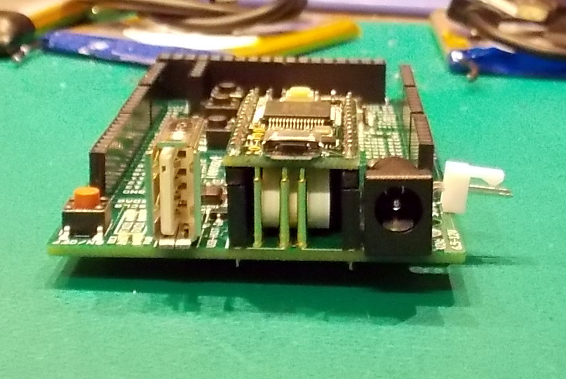
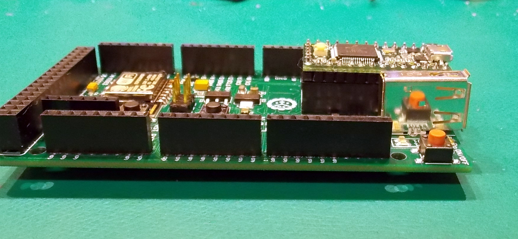
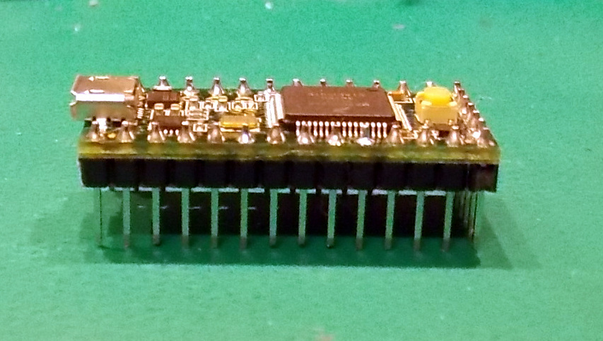
Partially Insert the male headers for the Teensy into the female headers, long-side down. This will stabilize them while you solder them to the Teensy.
Fit the Teensy onto the top of the male header pins and solder them from the top. The Teensy should rest on top of the black plastic spacer on the male headers.
Connect Flatflex to Teensy and Install in Socket
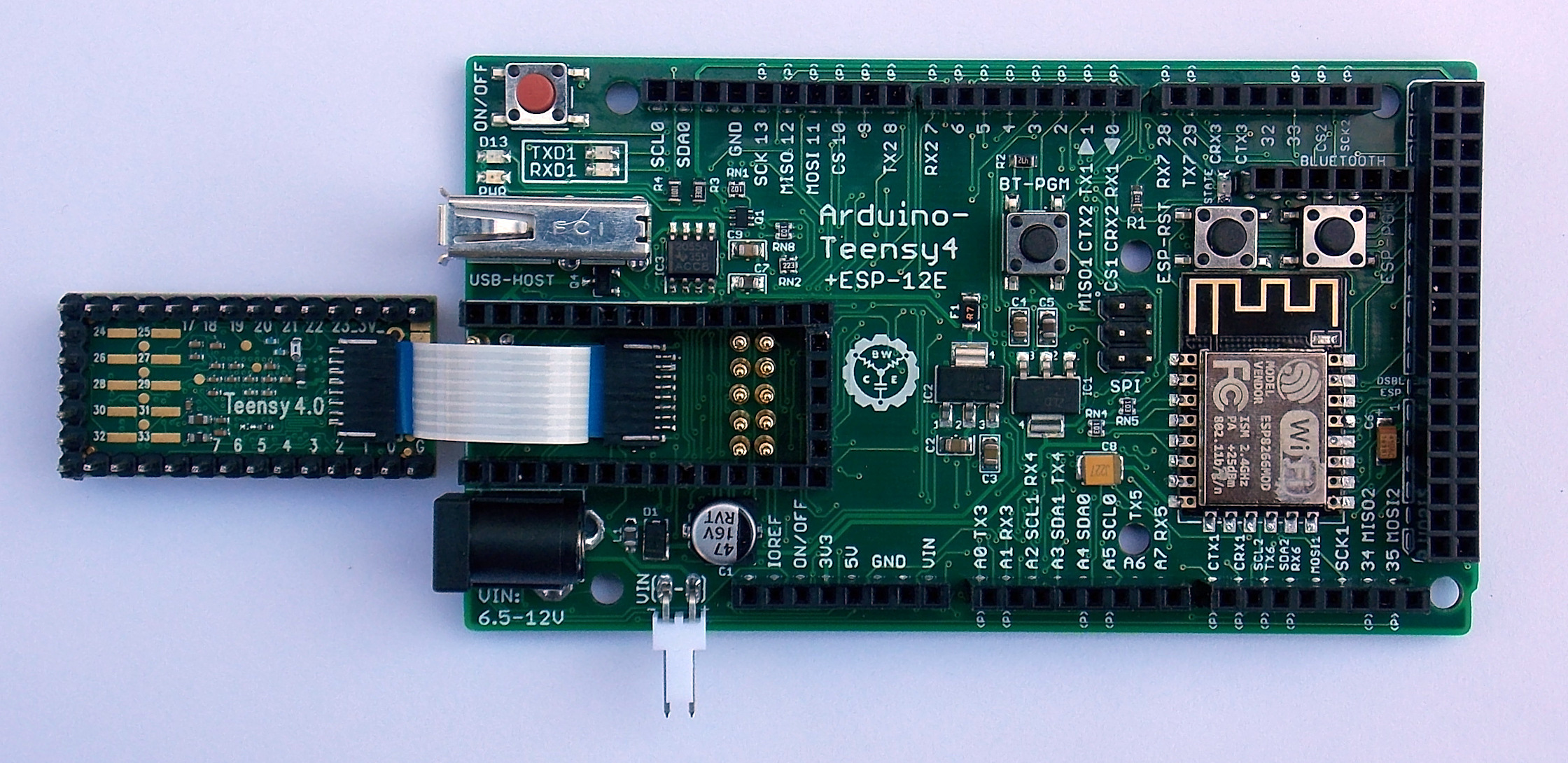
Use your fingernail or a blunt plastic tool to push the flatflex cable into the connector on the bottom of the Teensy. The silver side of the cable should face the Teensy and the blue side should be partially visible when fully inserted.
If you have a multi-meter available, ensure continuity between the pins on the connector on the bottom of the Teensy and the microSD card connector on the bottom of the main PCB. Ensure all pins make contact all the way through. If you find a pin that is not making connection, verify the soldering of both connectors and verify that the cable is inserted all the way.
If you damage the flatflex cable, you can order a new one from my Tindie store for $1 shipped.
Bend the flatflex cable close to the connector on the Teensy but not so sharply that you damage the cable or pull the cable out of the connector. You need to ensure that the cable will clear the 3 pogo pins at the front of the socket without pushing them out of alignment.
Install the Teensy into the socket. You might have to bend the flatflex cable a few times to get it to clear the pogo pins.
If the Teensy is being pushed out of the socket by the pogo pins, put a small drop of hot glue on the side where the headers meet after ensuring that the Teensy is fully-inserted. Hold the Teensy in place until the hot glue cools. Do not get glue on the pins on in the female header.
Complete Installation - Install Barrel Jack, USB and Molex Connectors
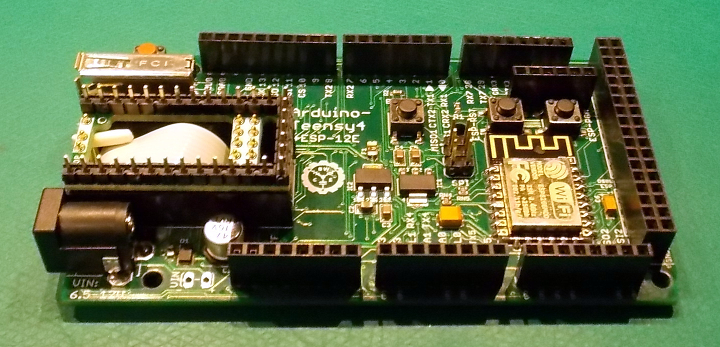
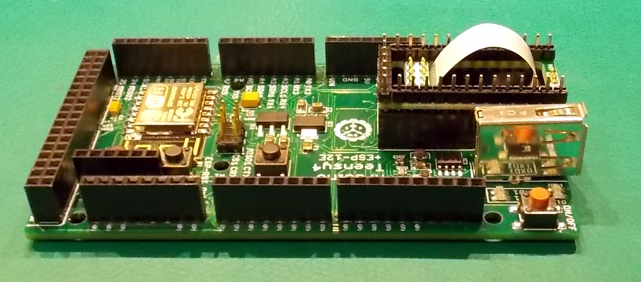
Insert the barrel jack into the PCB and solder from the bottom.
Insert the 2-pin Molex connector into the PCB and solder from the bottom.
Insert the USB connector into the main PCB and solder from the bottom.
If desired, use 90% Isopropyl Alcohol and some cotton swaps or cotton balls to remove excess solder flux from bottom of PCB.
Test Board
You can use the example sketches in my GitHub repository linked below to test the basic functions of the board:
https://github.com/cburgess5294/Arduino-Teensy4
You will need to install the latest version of the Arduino IDE and the libraries identified below in order to use the example sketches: