Arduino TVout Keyboard
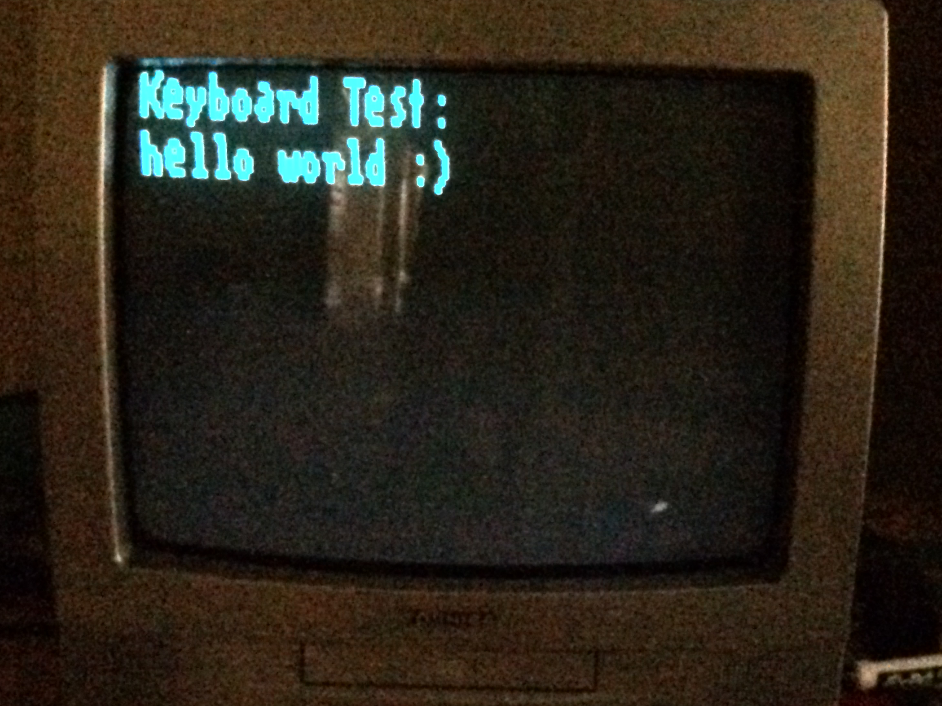
In this tutorial, you will learn how to use a PS2 keyboards and the Arduino TVout library to create a simple word processor. By the end of this tutorial, you will have the same thing show above.
Parts
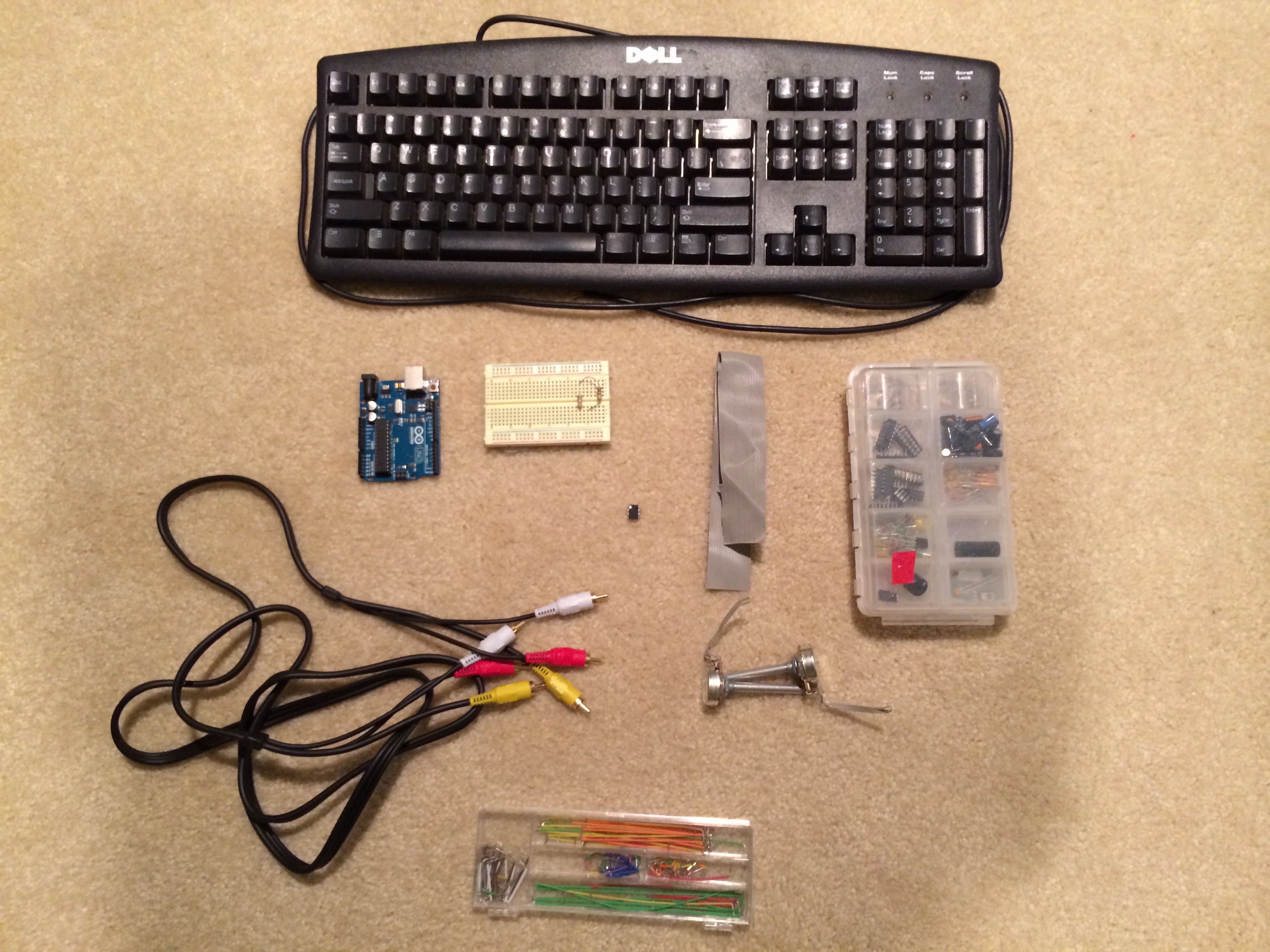
For this Instructable, you will need:
Hardware:
1.) An RCA compatible television.
2.) PS2 keyboard. If you have a USB keyboard, buy a converter. (Buy here)
3.) Arduino Uno
4.) Wire (ribbon cable)
5.) A 1k ohm (Brown, Black, Red) and a 470 ohm (Yellow, Purple, Brown) resistor
6.) If you do not own these resistors, use variable resistors
7.) Breadboard
8.) Breadboard connecters (Wire)
You will also need:
A soldering iron
Solder
Perf board
Pliers
X-acto knife (or any other kind of knife)
Software:
Creating Libraries Folder

If you haven't done this already, go to your Arduino folder and create a folder called libraries. If this folder already exists, do not do this. Next, unzip both libraries you just downloaded and put the folders into the libraries folder.
Changing TVout Beta

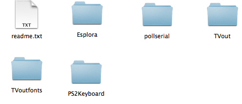

TVout beta has a few problems with it. To fix these problems, go to this link and download the files provided. Take these files and replace the pre-existing ones. This should fix some uploading bugs.
Moding the Keyboard
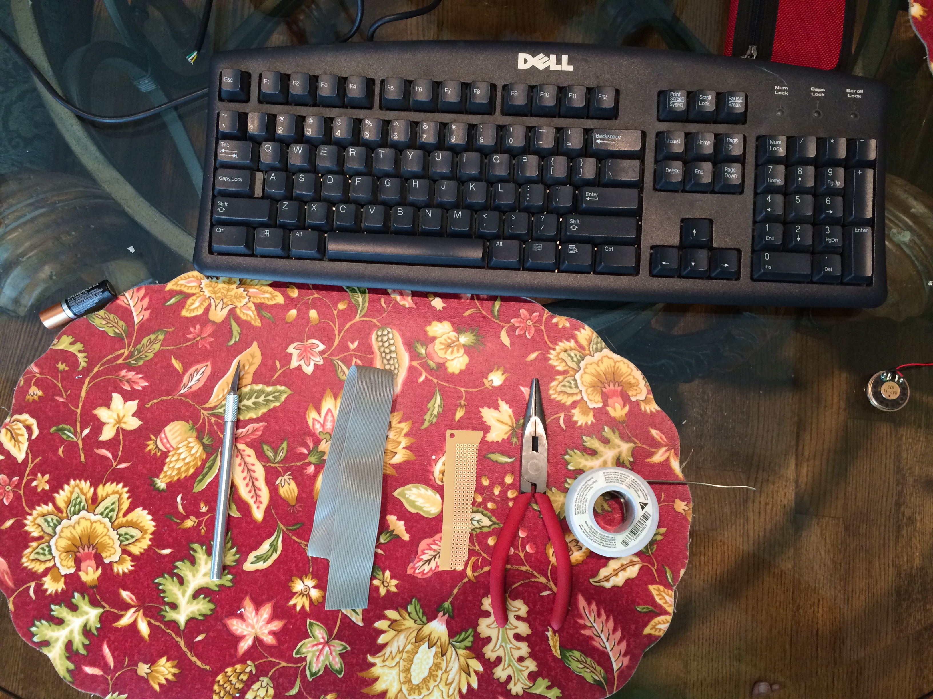
Gather these parts to mod the keyboard cable:
1.) PS2 keyboard
2.) X-acto knife (or other knife)
3.) Wire (ribbon cable)
4.) Perf board
5.) Pliers
6.) Solder
Stripping the Cable
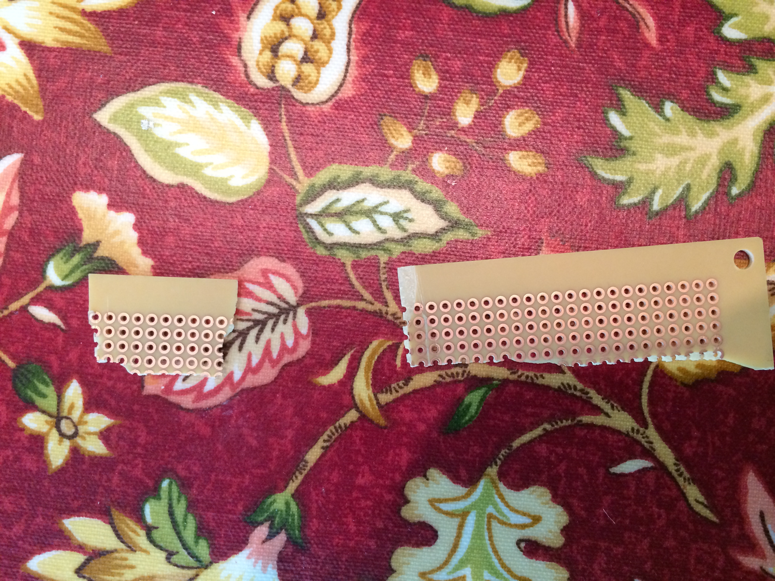
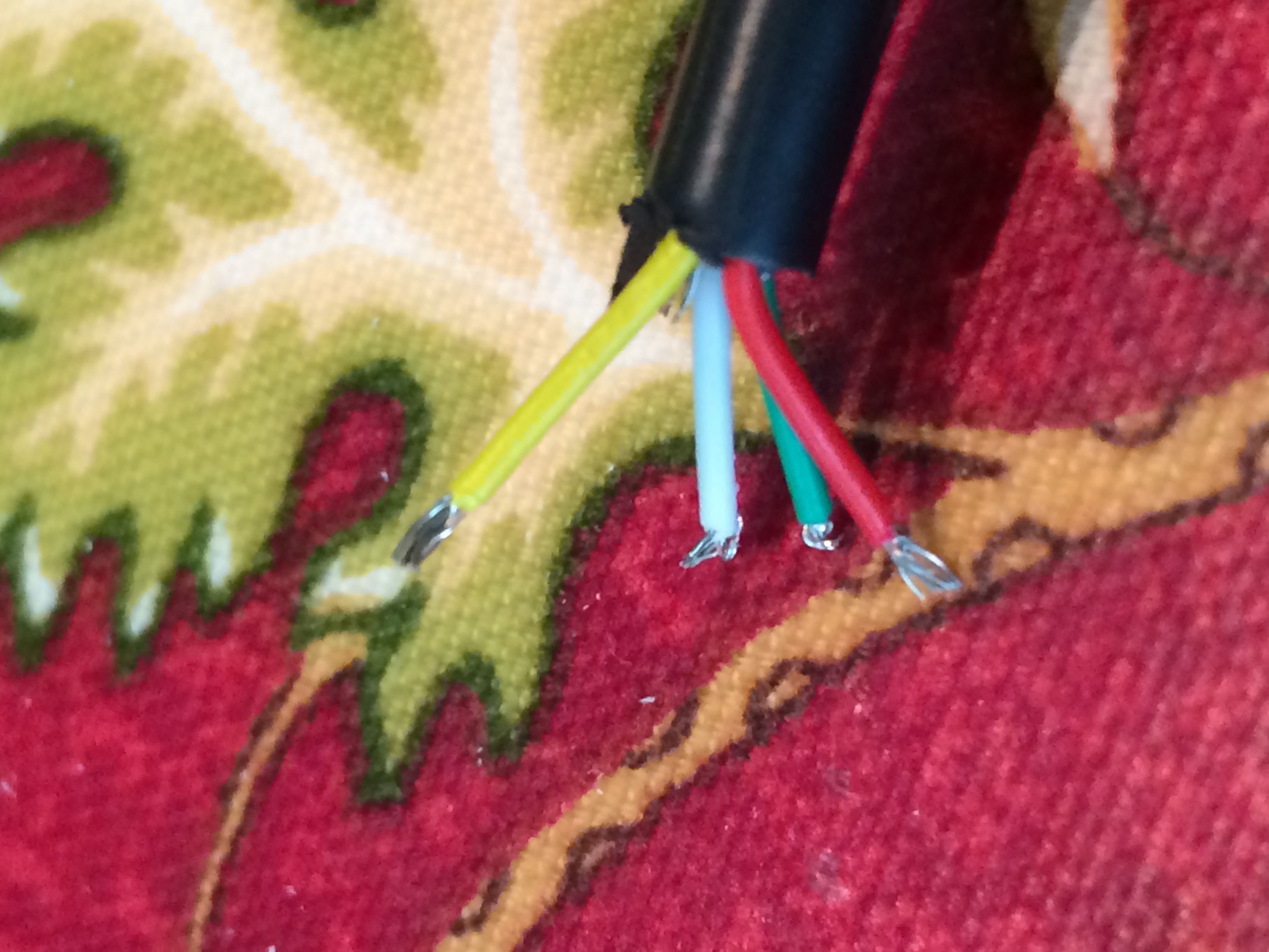
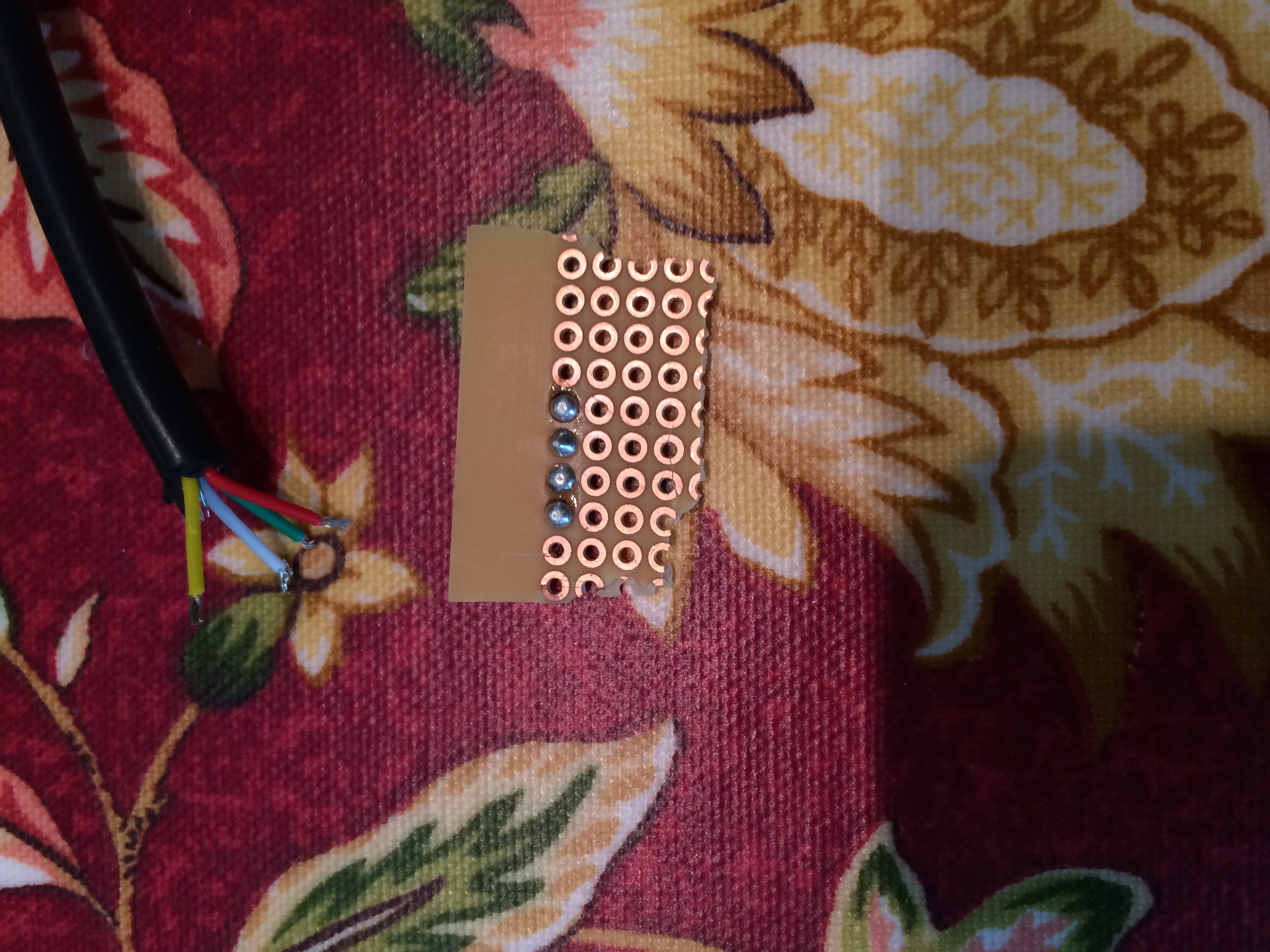
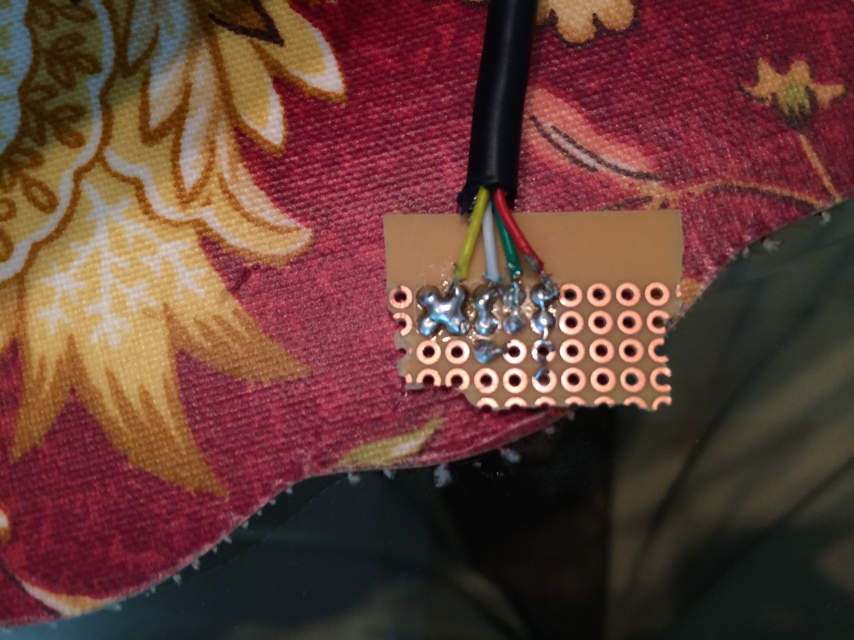
First, break the perf board as show. Next, strip the wires and add solder to the tips. Lastly, solder four pins onto the perf board. Make sure they are not touching. Solder the 4 colored wires onto the board.
Adding Ribbon Calbe
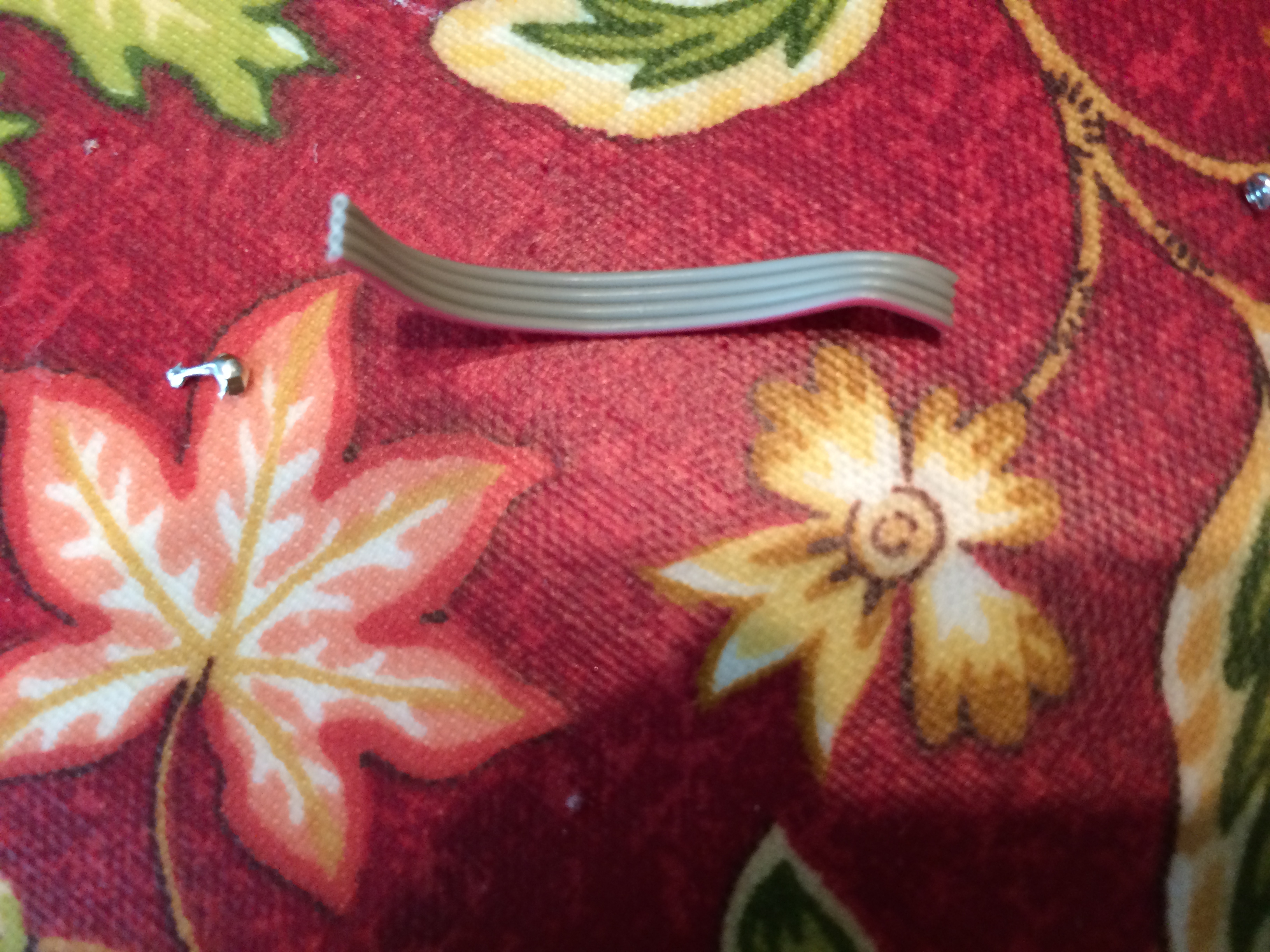
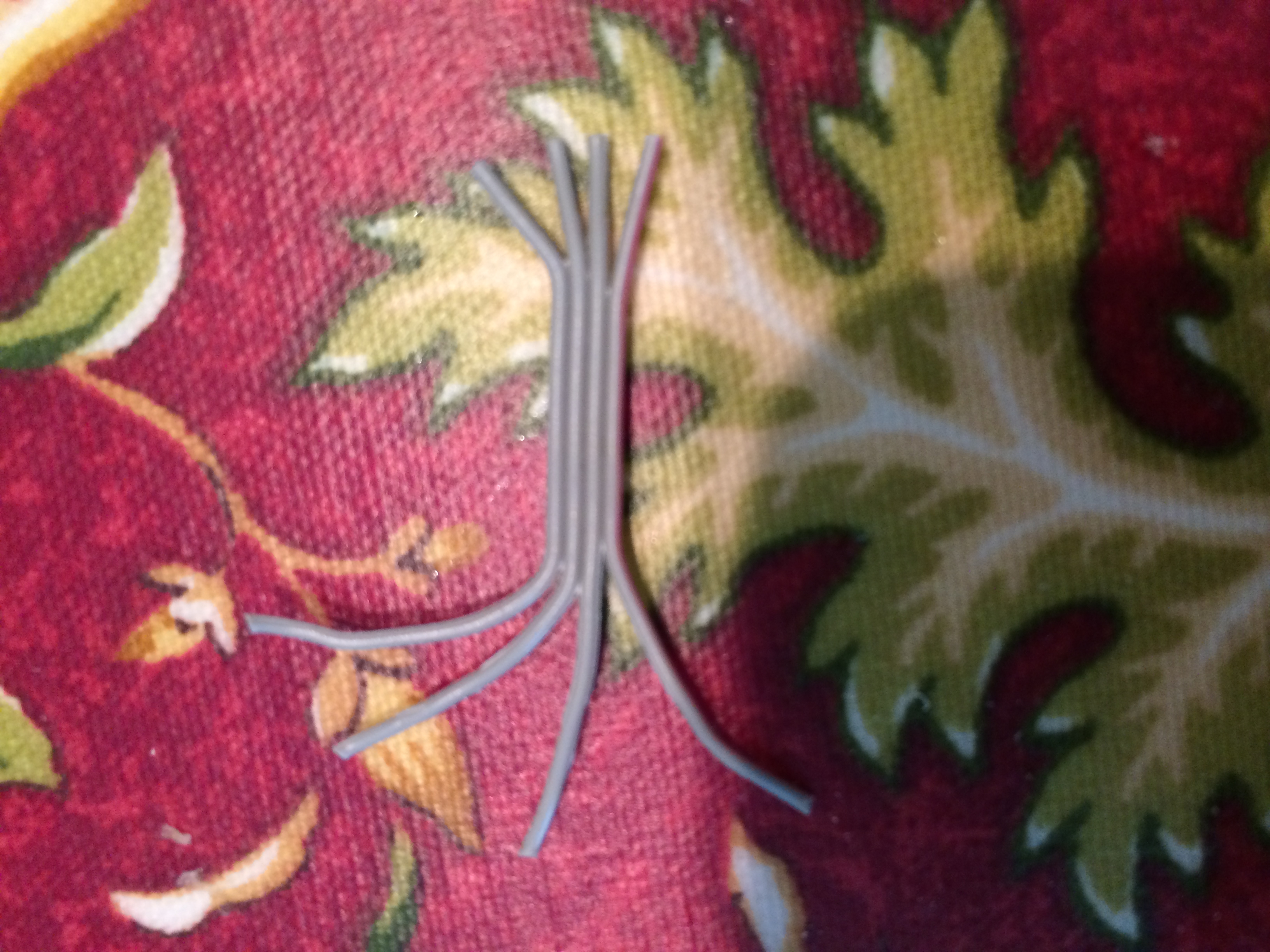
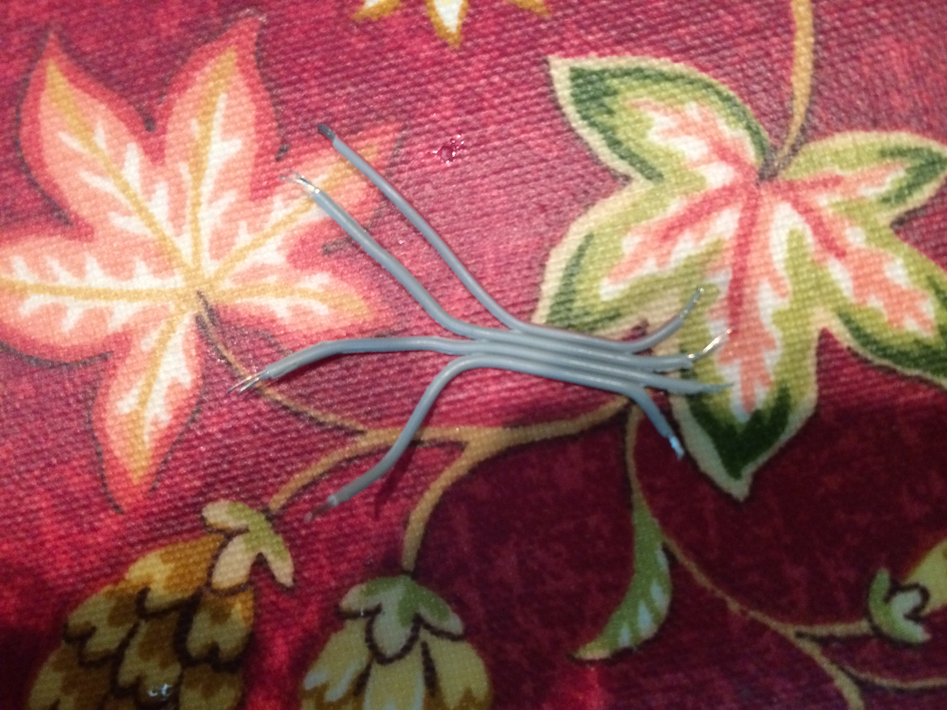
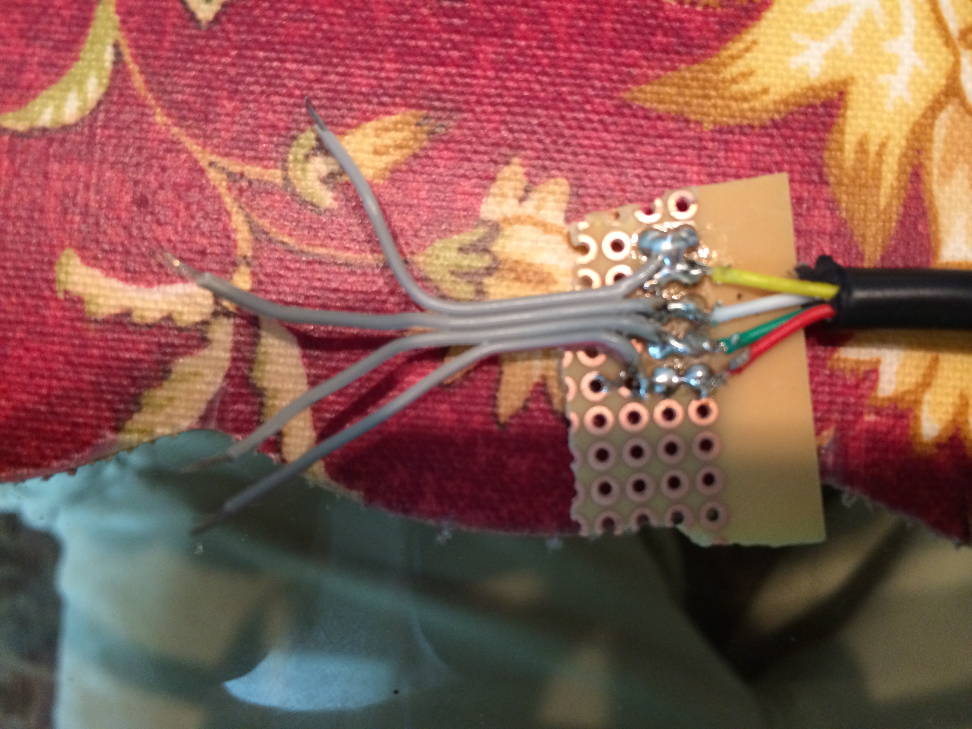
Create a 2 inch long strip of 4 wires with the ribbon cable. Pull the wires apart as show above. Strip the tips and add solder to each wire. Solder the smaller end to the wires on the perf board.
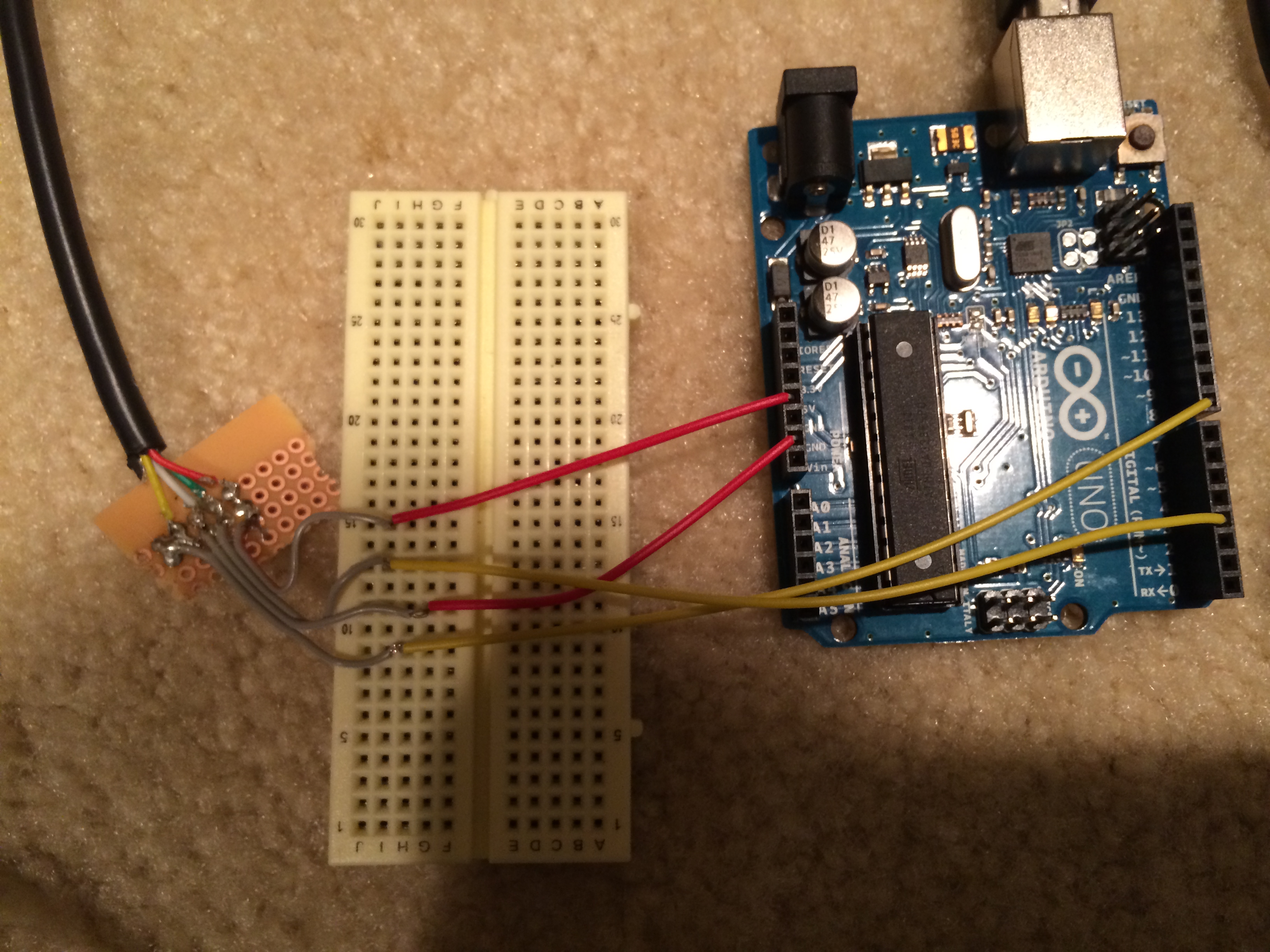
Connect the Keyboard to You Arduino
.jpg)
Connect the colored wires as follows:
Red: 5 volts
White: Ground
Green: Pin 3
Yellow: Pin 8
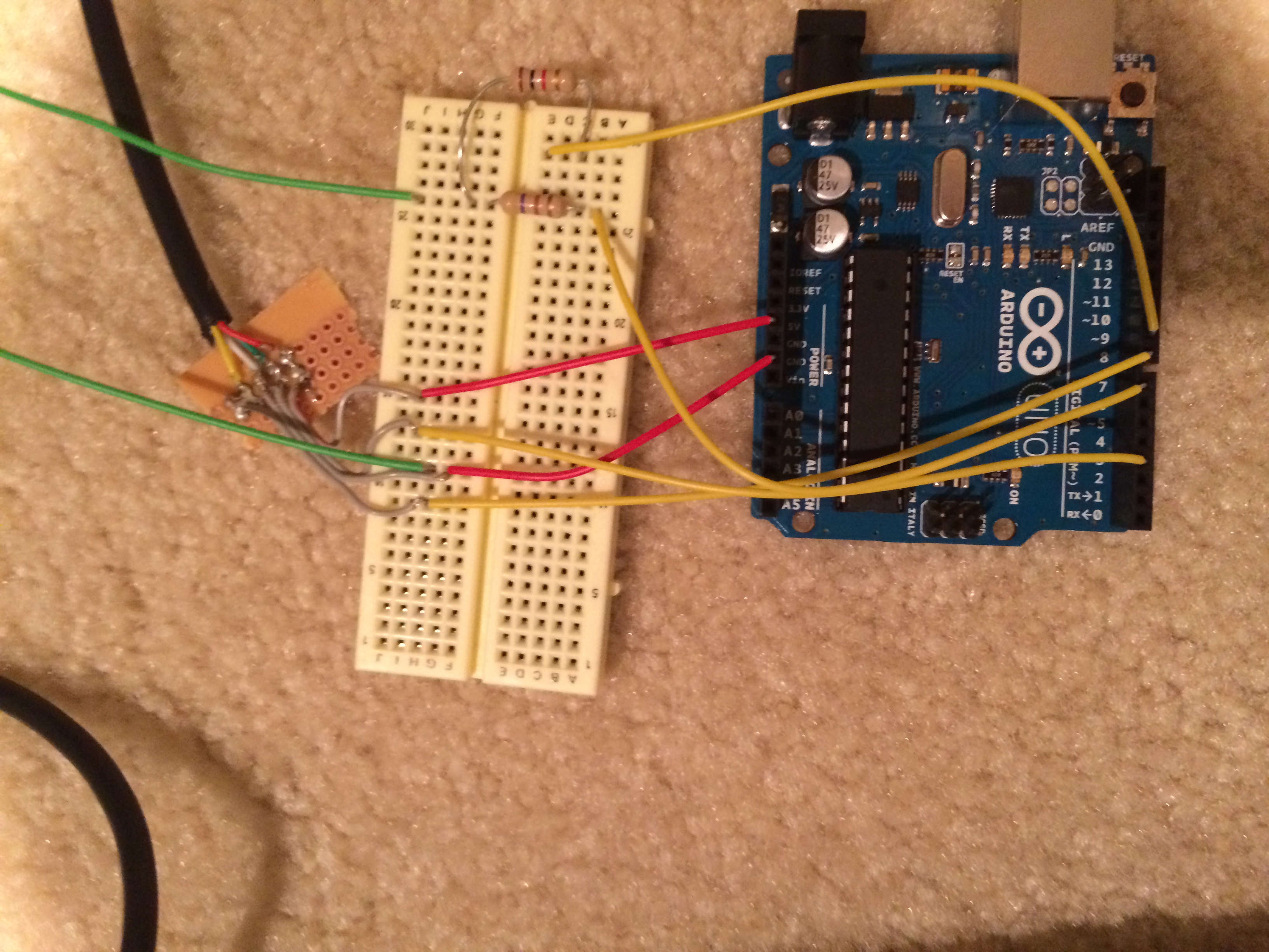
Connect to RCA
.jpg)
Connect to the Arduino as follows:
Pin 7: 470 ohm resistor
Pin 9: 1k ohm resistor
Connect to RCA as follows:
Connect both resistors to the signal line on the RCA cable
Connect the ground line to ground on the RCA cable
Upload Code
Upload the attached code to your Arduino. Make sure your Arduino is connected to the computer while uploading. While running the code, you an use either USB or the DC jack to power your project/
Downloads
Boot Up and Run!
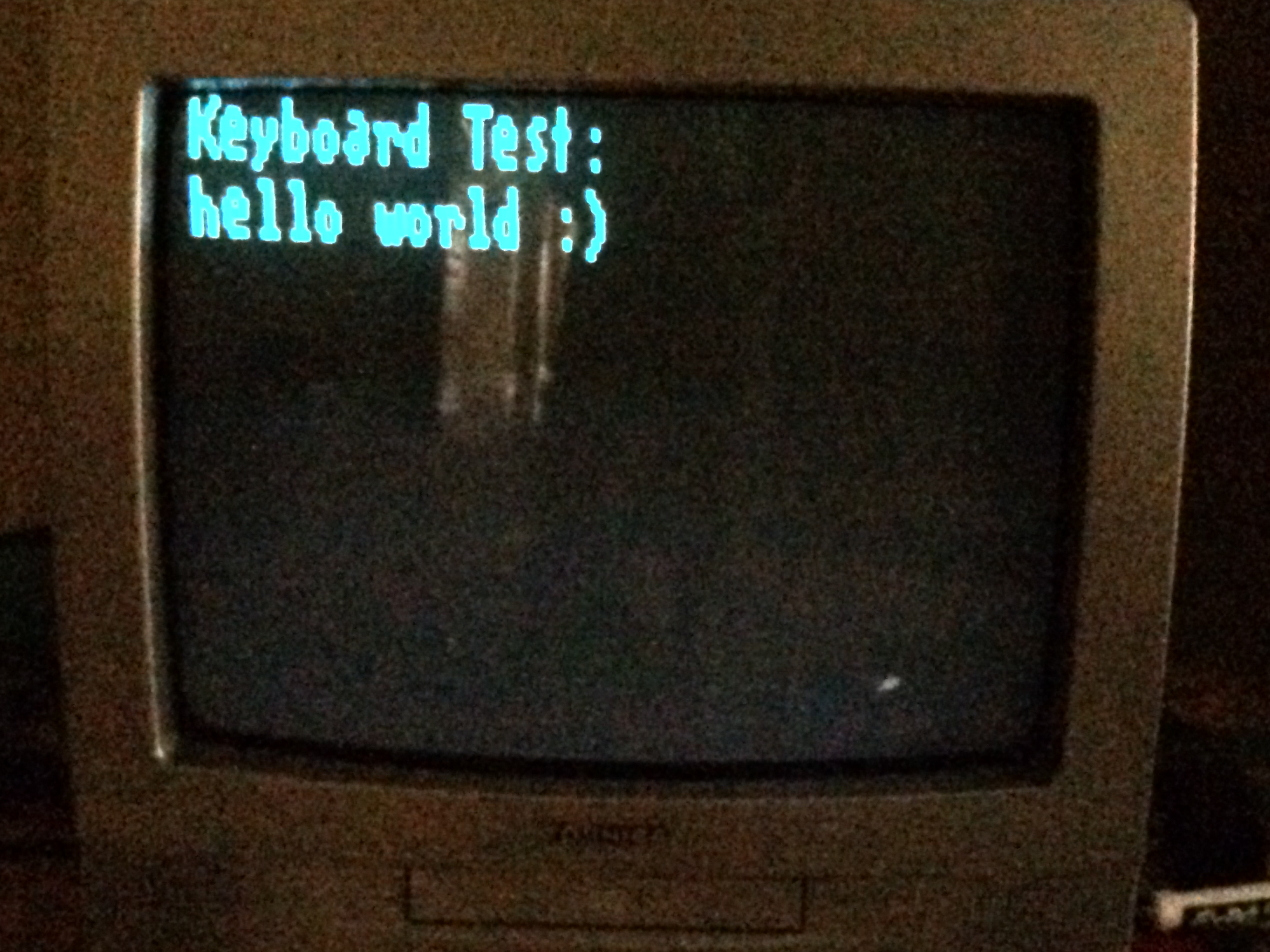
Feel free to leave in the comments what you did with this project. It is a little buggy, so feel free to fix it. Hope you enjoyed it!