Arduino Smart Home With Alexa & Google Assistant Using ESP-01 - IoT Project 2022
by techstudycell in Circuits > Arduino
18686 Views, 25 Favorites, 0 Comments
Arduino Smart Home With Alexa & Google Assistant Using ESP-01 - IoT Project 2022
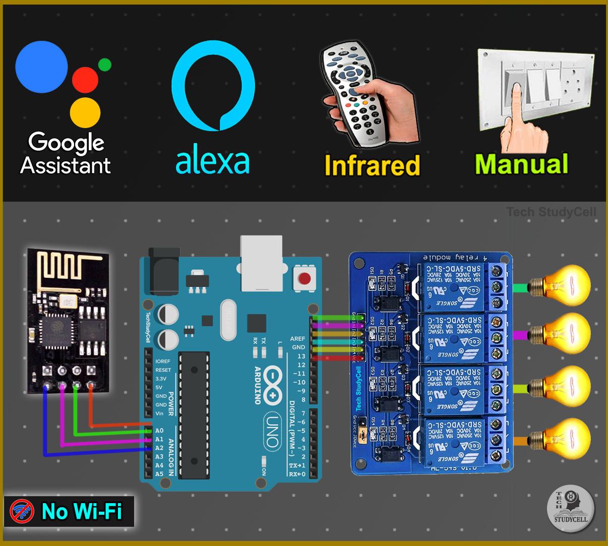
In this IoT project, I have shown how to make an IoT-based Arduino Smart Home with Google Assistant & Alexa using ESP-01 to control 4 home appliances with voice commands, IR remote, and manual switches. If the internet is not available, then you can control the home appliances from IR remote & manual switches. During the article, I have shown all the steps to make this smart home system.
This Arduino Home Automation system has the following features:
- Control appliances with Google Assistant.
- Control appliances with Alexa.
- Used Arduino EEPROM to remember previous states
- Control appliances with IR remote.
- Control appliances manually with switches or pushbuttons
- Monitor real-time feedback in the Google Home and Amazon Alexa App.
- Control home appliances manually without internet.
- All resources used for this project are FREE.
So if you follow all the steps, you can easily make this IoT project just by using Arduino UNO, ESP01, and relay module.
Although the PCB is not mandatory, I have used PCB to make the circuit compact and give the project a professional look.
Supplies
Required Components for this IoT Project (without PCB)
- Arduino UNO
- ESP-01
- 1838 IR receiver (with metal case)
- 1k, 2k, 4.7k resistors (1/4 watt)
- 5-mm LED
- 1117 3.3V voltage regulator
- 4-channel 5V SPDT Relay Module
- Switches or Push Buttons
- FTDI232 USB to TTL
- 5V DC supply.
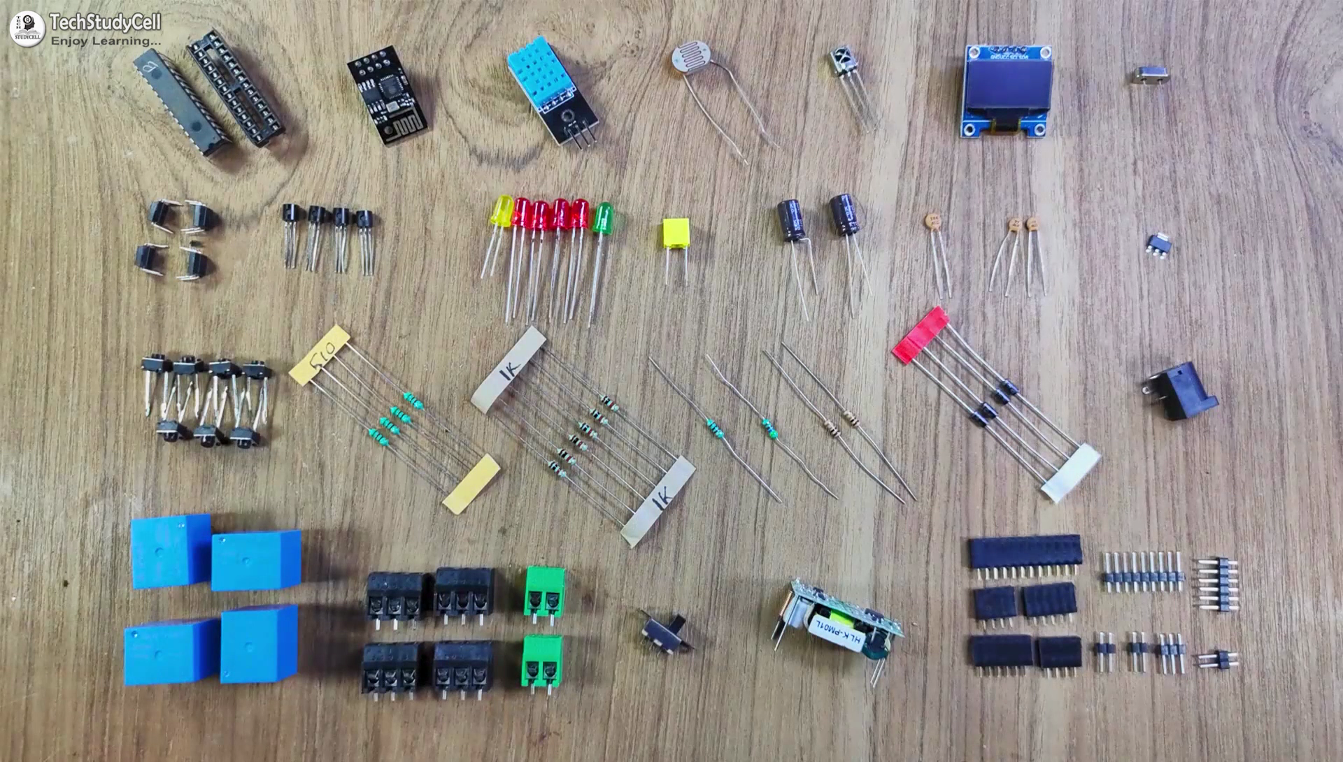
Required Components for the Arduino control Relay PCB:
- Atmega328P microcontroller
- ESP8266 ESP01
- PC817 Optocuplors (4 no)
- 510-ohm 0.25-watt Resistor (4 no) (R1 -- R4)
- 1k 0.25-watt Resistors (6 no) (R5 -- R10)
- 2k 0.25-watt Resistor
- 4.7k 0.25-watt Resistor
- 10k 0.25-watt Resistors (2no)
- 22pF ceramic capacitor
- 104 ceramic capacitor
- 220uF 25V Capacitor (2no)
- 1uF Box capacitor (1no)
- 16MHz Crystal
- LED 5-mm (6 no)
- 1N4007 Diodes (4 no) (D1 -- D4)
- Push Buttons (8 no)
- BC547 Transistors (4 no)
- Relays 5v (SPDT) (4 no)
- Terminal Connectors
- Jumper (5no)
- Switch (1no)
- Hi-link ac-dc 220v-5v
How This Arduino IoT Project Works?
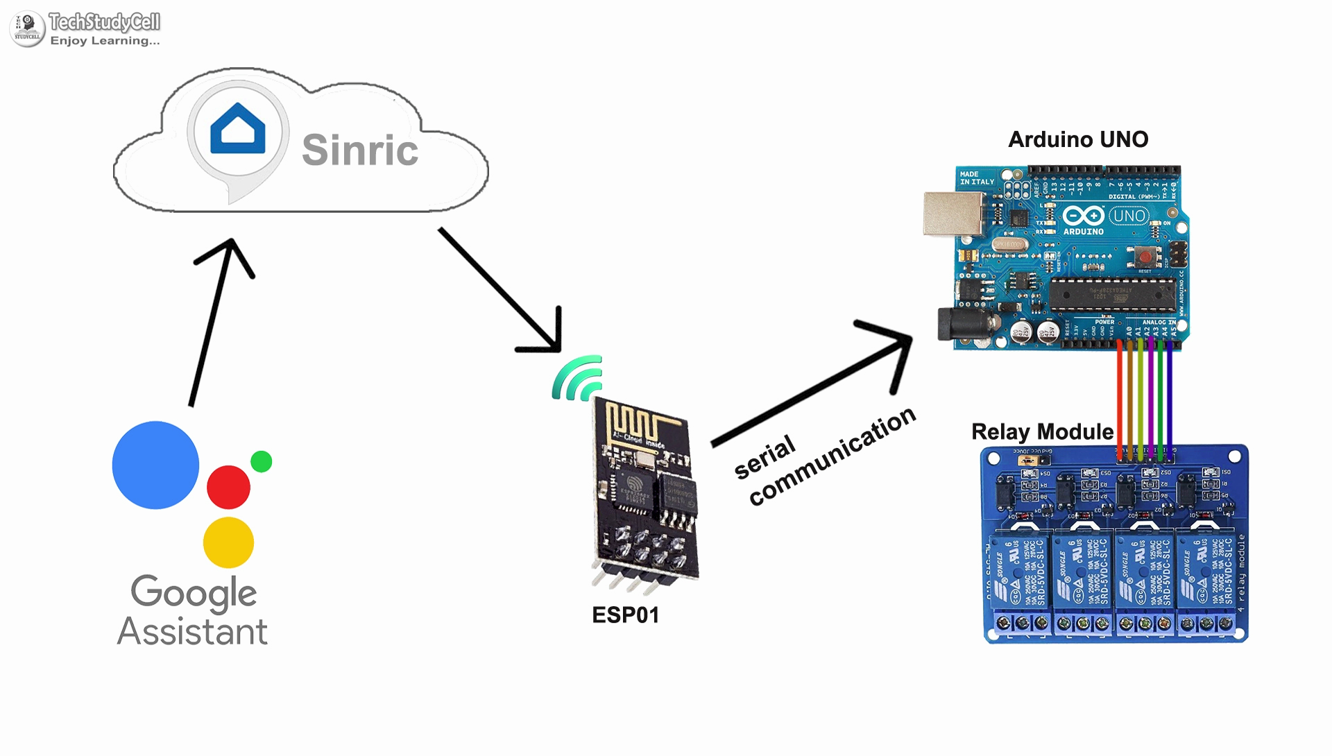
This Arduino ESP8266 Home Automation works in the following steps.
- When you ask Google assistant to control appliances, it sends the signal to the Sinric server,
- ESP-01 will receive the signal from the Sinric through the internet.
- ESP-01 sends the same signal to Arduino through the serial terminal.
- Arduino UNO will process that signal and accordingly turn on or off the relays.
- Arduino sends the feedback to ESP-01 through the Serial communication.
- ESP-01 sends feedback to the Sinric server through the internet.
- Real-time feedback can be monitored in the Google Home or Amazon Alexa app.
Circuit Diagram of the ESP01 Arduino Control Relays
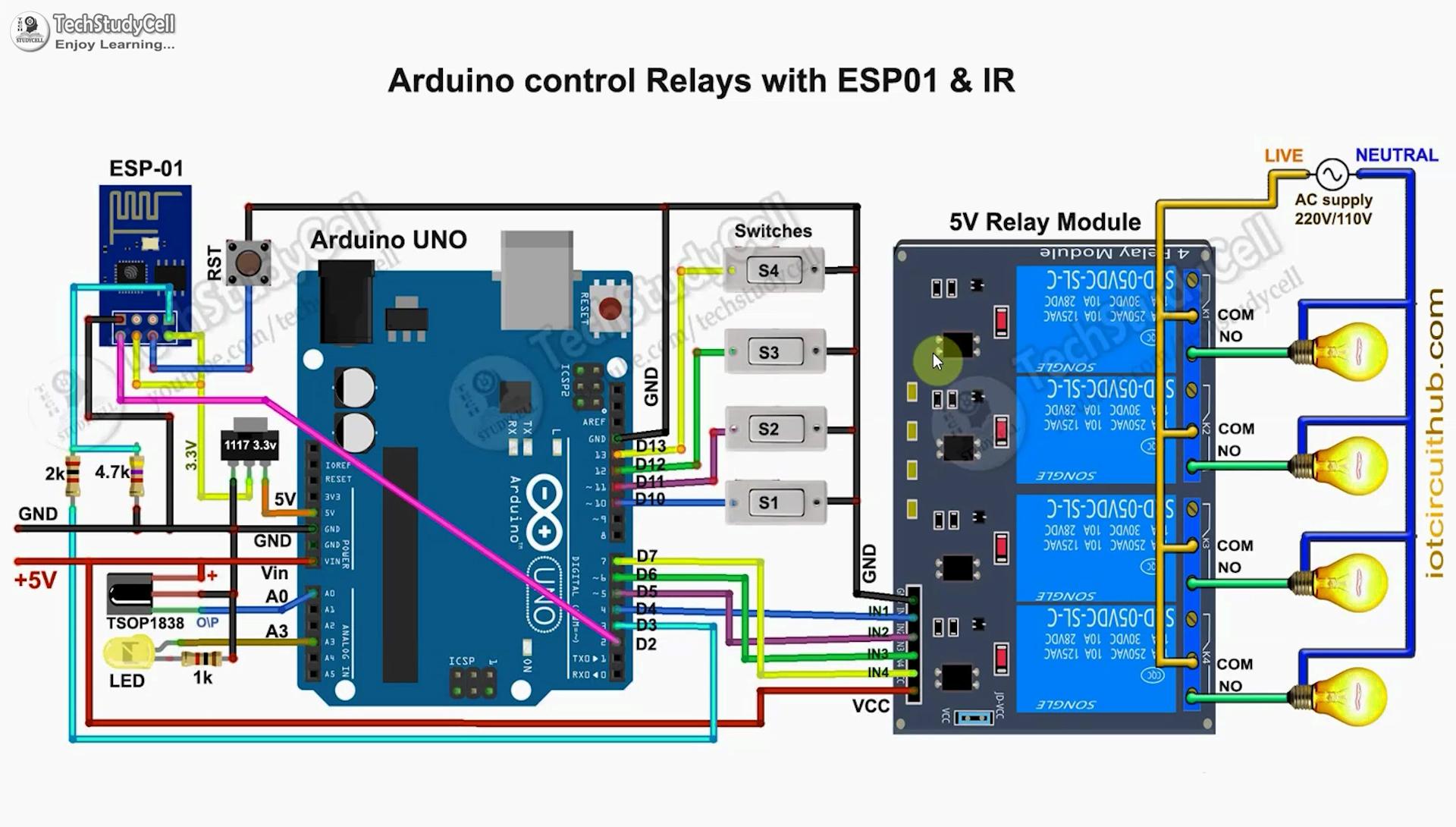
The circuit is very simple, I have used the digital pins D4, D5, D6 & D7 to control the 4 relays.
And the digital pins D10, D11, D12 & D13 are connected with switches to control the 4 relays manually.
The output pin of the IR receiver is connected with A0.
I have used the INPUT_PULLUP function in Arduino IDE instead of using the pull-up resistors.
I have used D7 as RX and D8 as TX for the serial communication with the ESP-01 module.
I have made a voltage divider using 2k and 4.7k resistors to drop down the 5volt logic level to 3.3volt logic level for the serial communication with the ESP-01 module.
If you use the momentary pushbutton then just connect the pushbutton across the digital pins and GND instead of switches.
If you use Arduino UNO then you can use the 3.3V pin instead of the 1117 3.3V regulator to supply the ESP01 but for Arduino Nano, you have to use the 1117 3.3V voltage regulator.
I have used a 5V mobile charger to supply the smart relay module.
Please take proper safety precautions while working with high voltage.
Create an Account in Sinric Pro
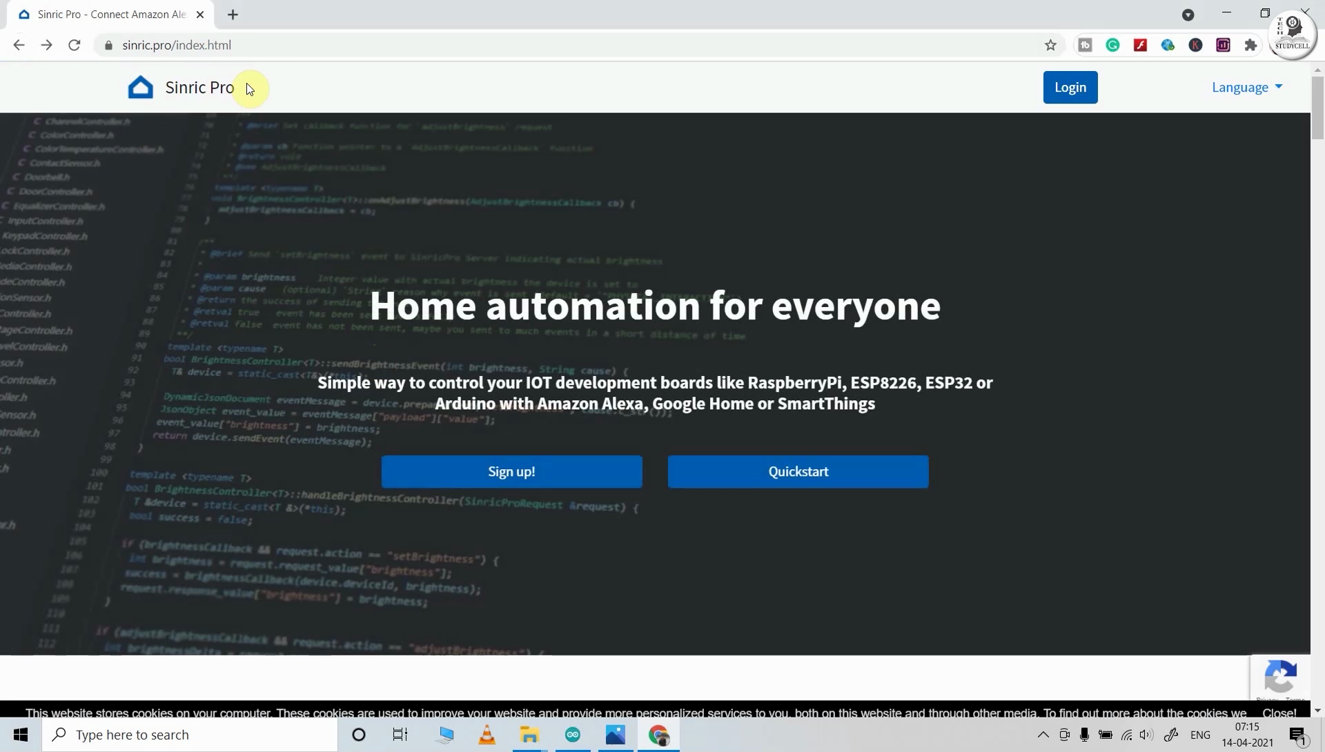
First, visit https://sinric.pro/
You have to create an account in Snric Pro.
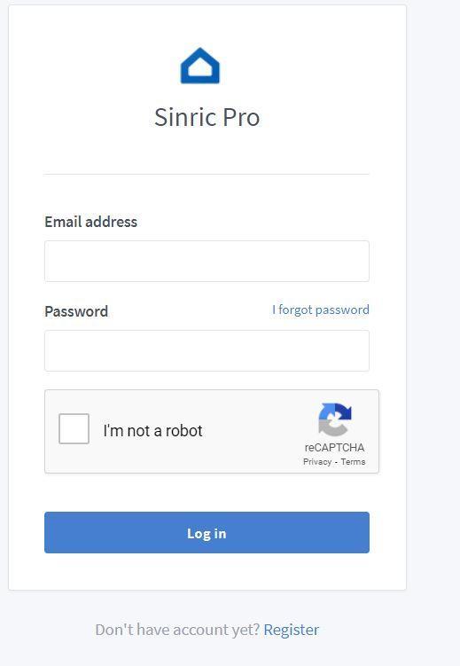
Then log in to Sinric Pro Account.
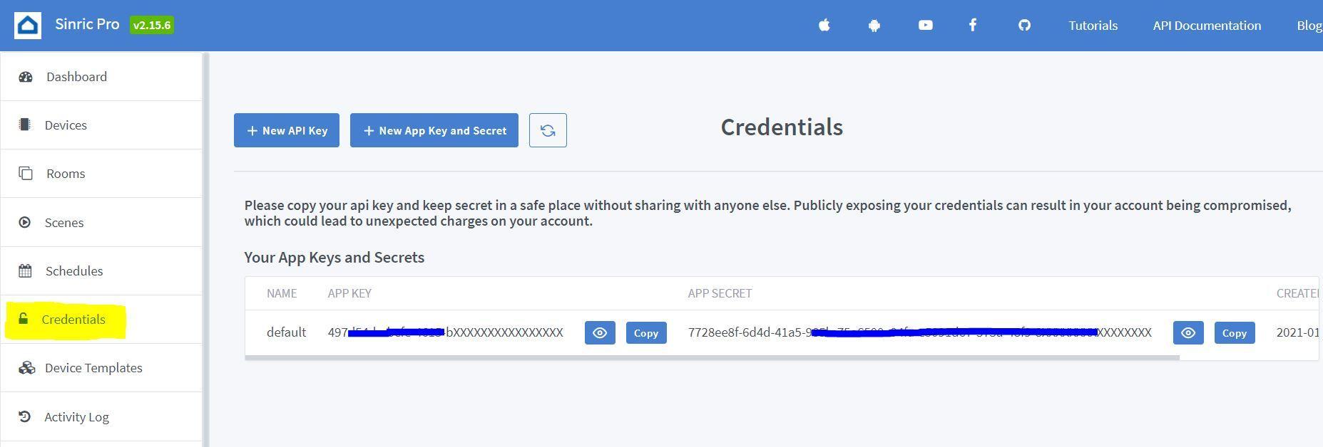
You will get an APP KEY and APP SECRET for the account, which will be required in the code.
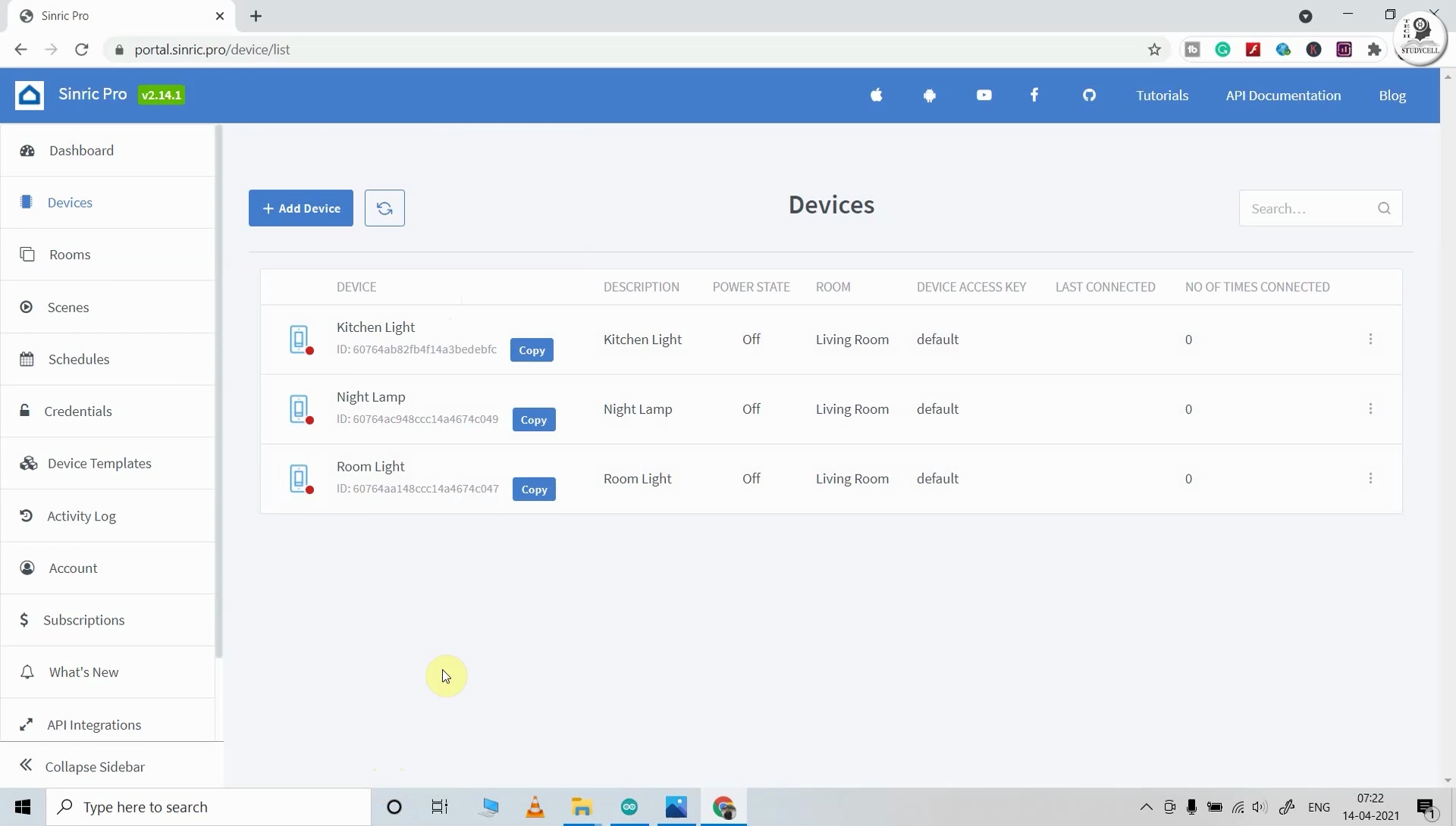
Add Room and Devices in Sinric Pro
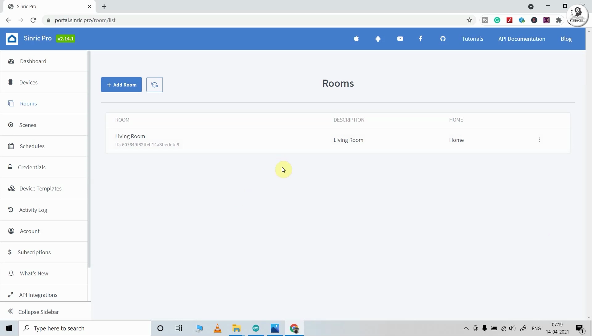
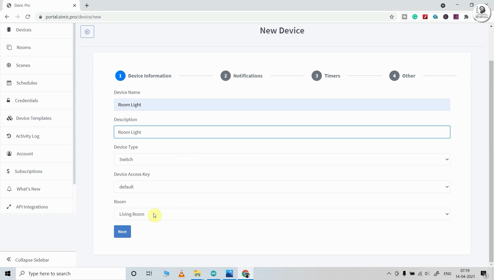
After that add a room and give a nickname to that room (Ex: Living Room)
Then Add devices one by one and give the nickname for each device. Sinric will assign a unique device ID for each device.
Here, I have used the free Sinric Pro account, so I can add a maximum of 3 devices for free.
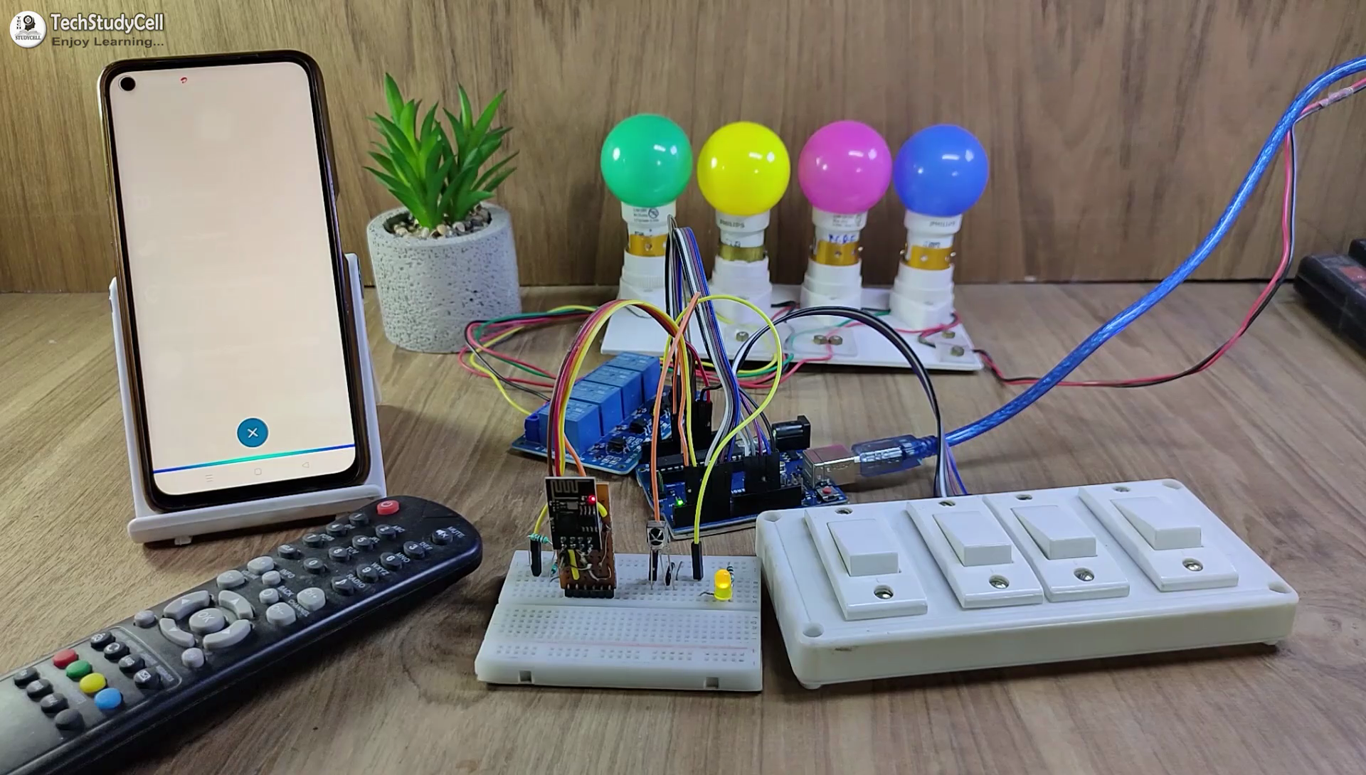
Testing the Circuit Before Designing the PCB

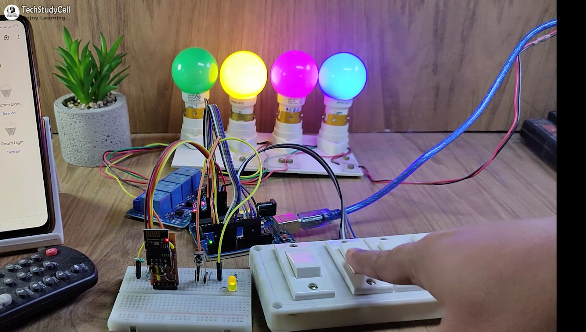
Before designing the PCB, I have made the circuit with Arduino UNO, ESP01, some resistors, and an IR receiver for testing all the features.
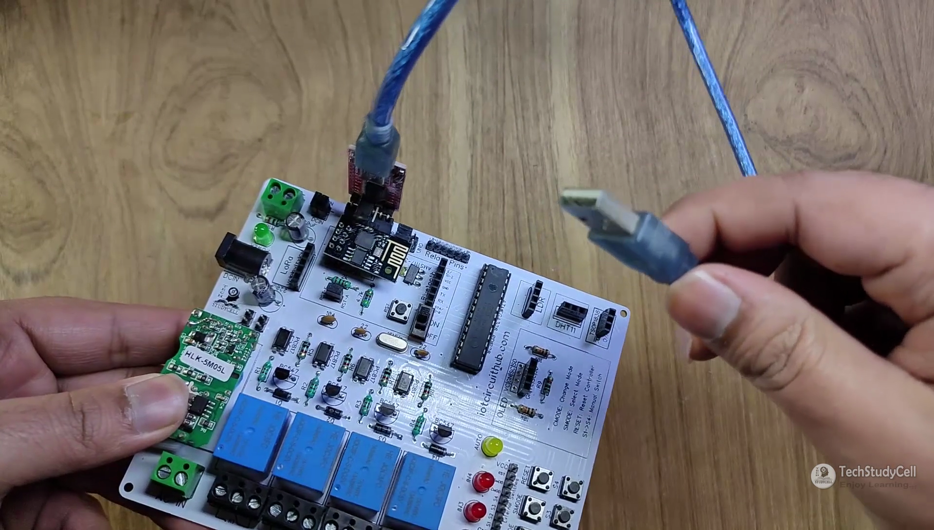
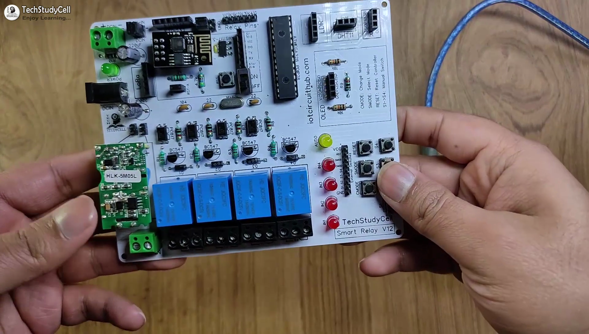
Design the PCB for This Smart Home System

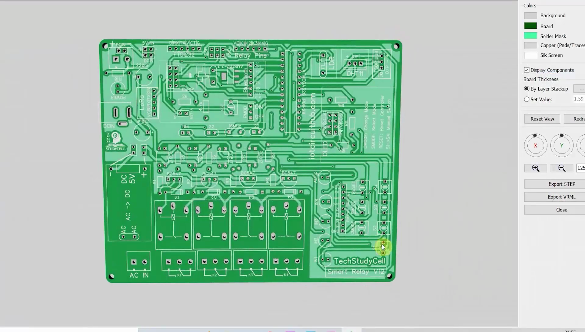
To make the circuit compact and give a professional look, I have designed the PCB after testing all the features of the smart relay module.
You can download the PCB Gerber file of this home automation project from the following link:
Order the PCB
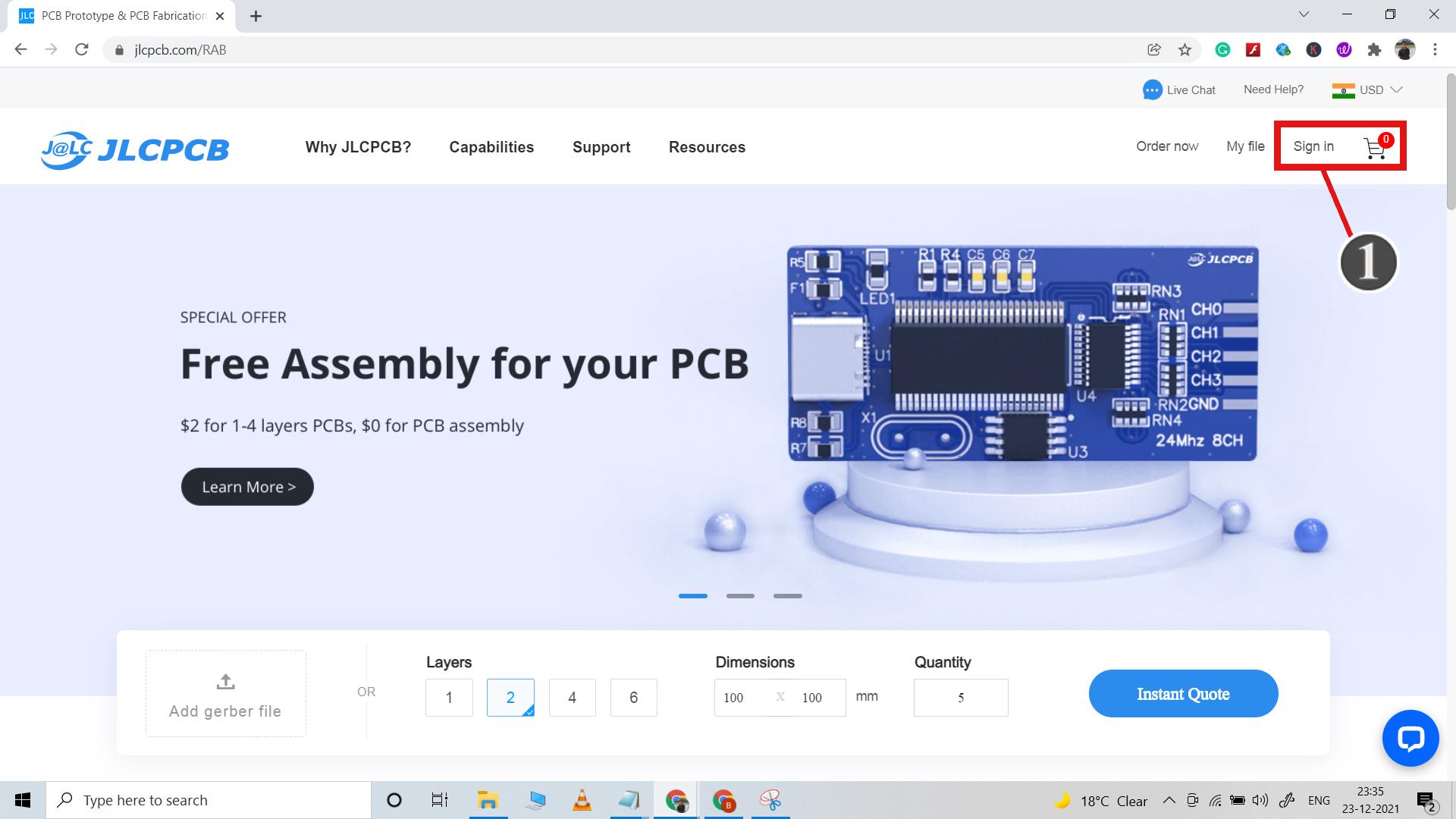
After downloading the Garber file you can easily order the PCB from JLCPCB.
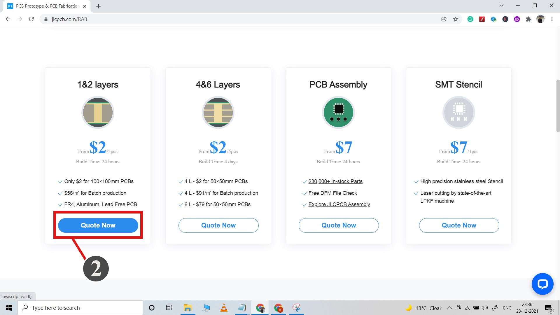
1. Visit https://jlcpcb.com and Sign in / Sign up.
2. Click on the QUOTE NOW button.
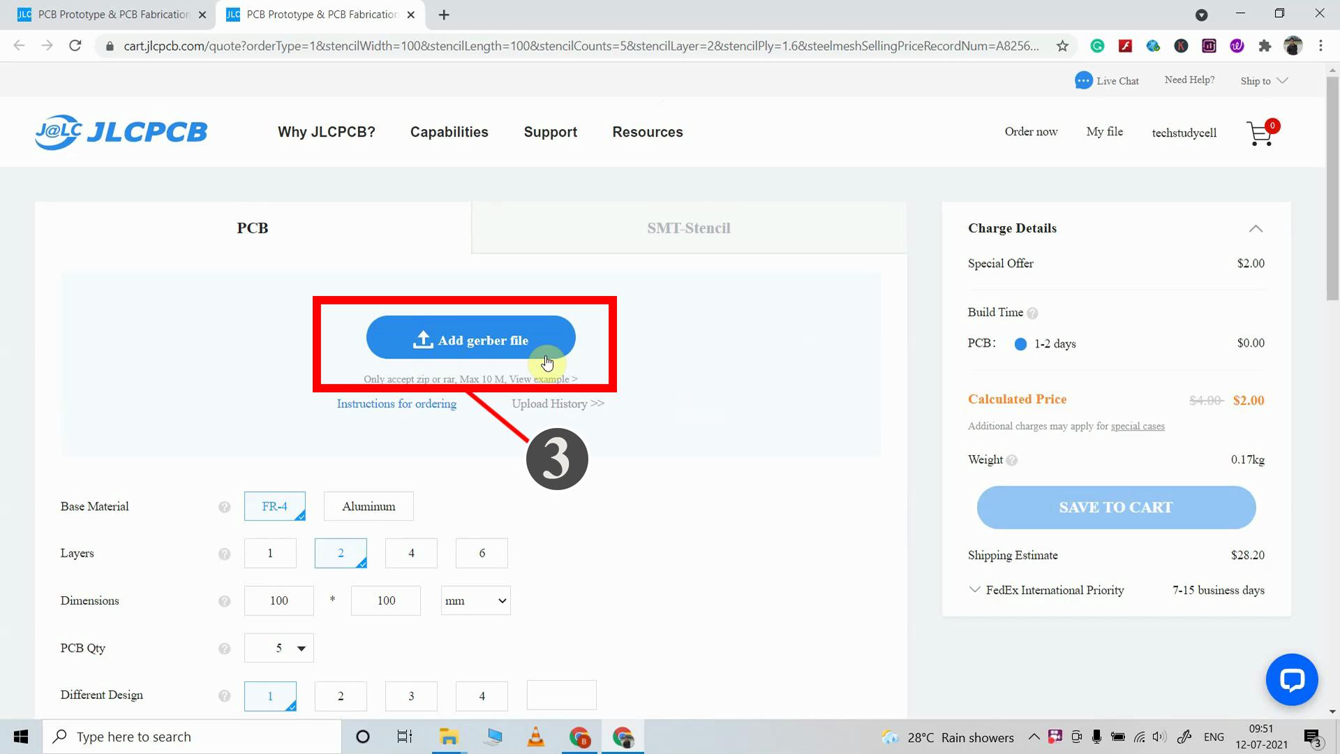
3. Click on the "Add Gerber file" button. Then browse and select the Gerber file you have downloaded.
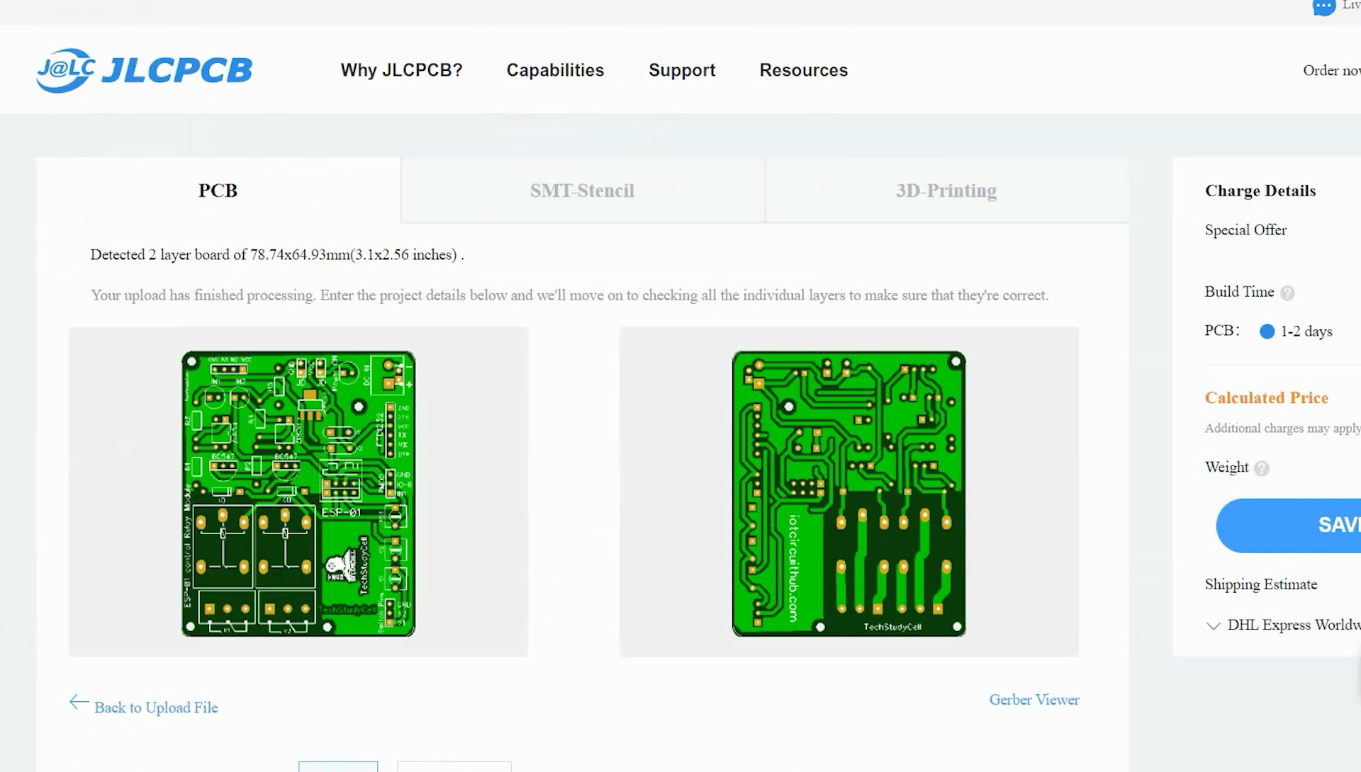
Uploading the Gerber File and Set the Parameters
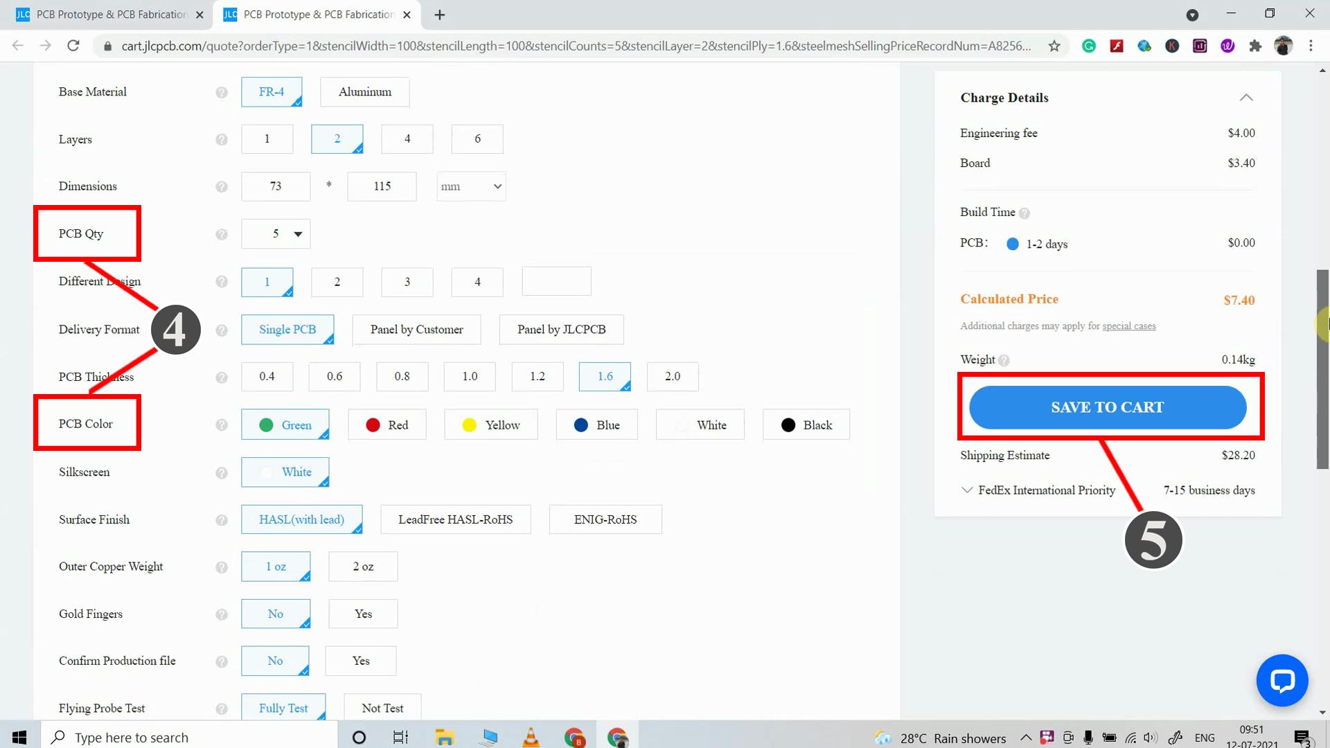
4. Set the required parameter like Quantity, PCB masking color, etc
5. After selecting all the Parameters for PCB click on SAVE TO CART button.
Select Shipping Address and Payment Mode
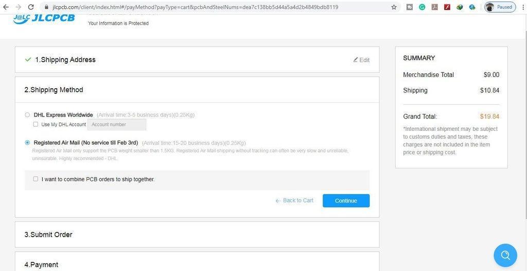
6. Type the Shipping Address.
7. Select the Shipping Method suitable for you.
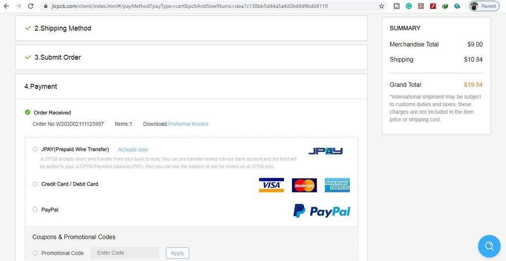
8. Submit the order and proceed with the payment. You can also track your order from JLCPCB.com.
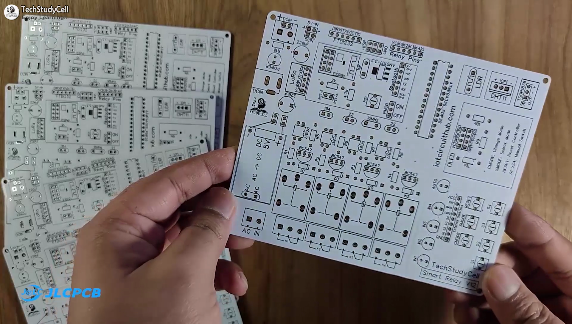
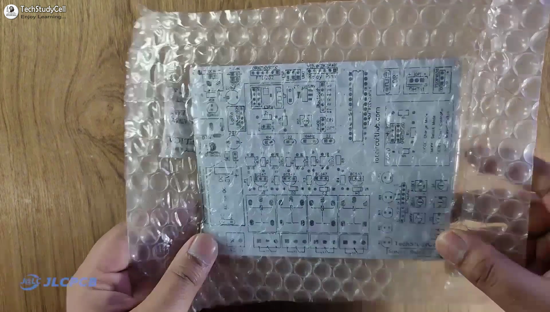
My PCBs took 2 days to get manufactured and arrived within a week using the DHL delivery option.
PCBs were well packed and the quality was really good at this affordable price.
Get the IR Codes (HEX Code) From Remote
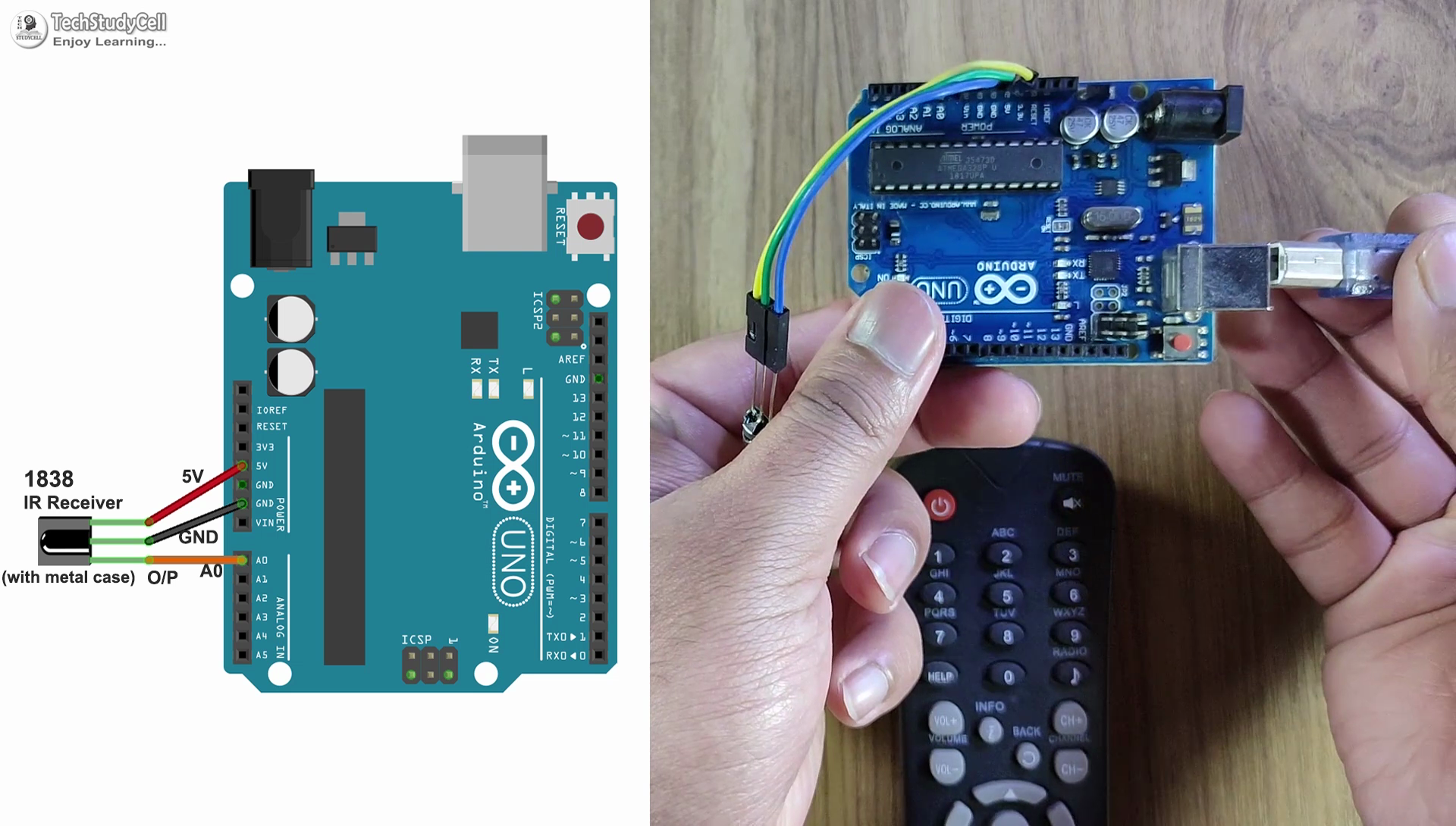
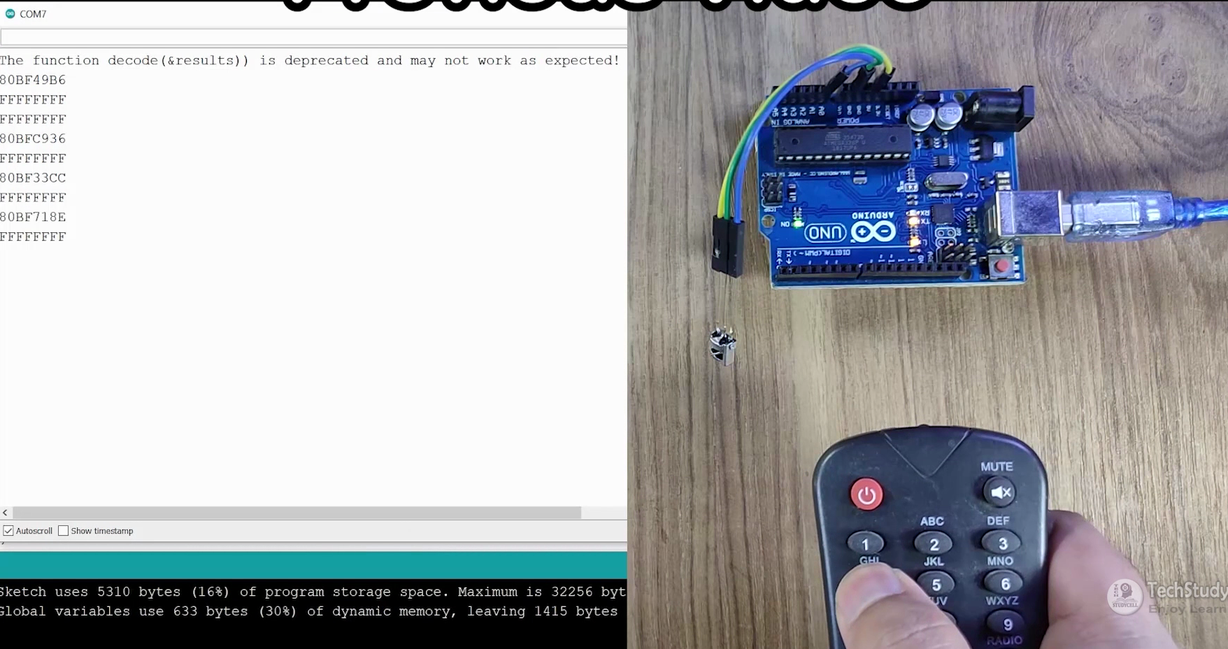
Now, to get the HEX codes from the remote, first, we have to connect the IR receiver output pin with the A0 pin of Arduino UNO.
And give the 5V across the VCC and GND. The IR receiver must have a metallic casing, otherwise, you may face issues.
Then follow the following steps to get the HEX codes:
- Install the IRremote library in Arduino IDE.
- Download the attached code, and upload it to Arduino UNO.
- Open Serial Monitor with Baud rate 9600.
- Now, press the IR remote button.
- The respective HEX code will populate in the serial monitor.
- Save all the HEX codes in a text file. You have to update these HEX codes in the main sketch.
Downloads
Program the ESP8266 ESP-01 With Arduino IDE
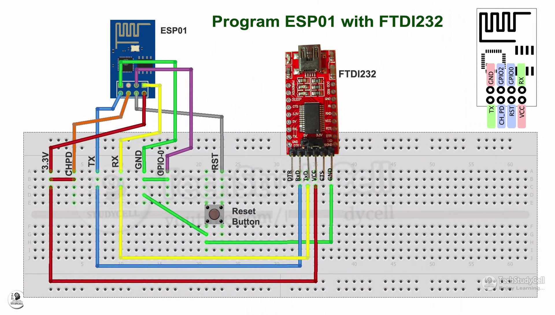
If you use the PCB, then you can easily go to program mode with a switch (PMOD) and directly connect the FTDI232 USB to the serial interface board with ESP-01.
Otherwise, you refer to this circuit to program the ESP-01. During programming, the GPIO-0 and GND should be connected.
First, download the attached source code & install all the required libraries mentioned in the code.
Required Arduino Libraries:
- Sinric Pro
- ArduinoJson
- WebSockets
Then enter the WiFi credentials:
#define WIFI_SSID "YOUR-WIFI-NAME"
#define WIFI_PASS "YOUR-WIFI-PASSWORD"
Enter the APP KEY and APP SECRET from the Sinric pro account Credential menu.
#define APP_KEY "YOUR-APP-KEY"
#define APP_SECRET "YOUR-APP-SECRET"
Enter the Device IDs from the Sinric pro account Devices menu.
#define device_ID_1 "SWITCH_ID_NO_1_HERE"
#define device_ID_2 "SWITCH_ID_NO_2_HERE"
#define device_ID_3 "SWITCH_ID_NO_3_HERE"
#define device_ID_4 "SWITCH_ID_NO_4_HERE"
Now select the "Generic ESP8266 Module" and proper PORT. Then upload the code to ESP01 Board.
After uploading the code, turn off the PMOD switch on the PCB and press the reset button.
Downloads
Program the Arduino UNO or ATmega328P With Arduino IDE
In the PCB I have used an ATmega328P microcontroller, so I have used FTDI232 USB to TTL board to program the microcontroller (Refer to tutorial video).
But if you don't use PCB then you can directly connect the Arduino UNO with the laptop.
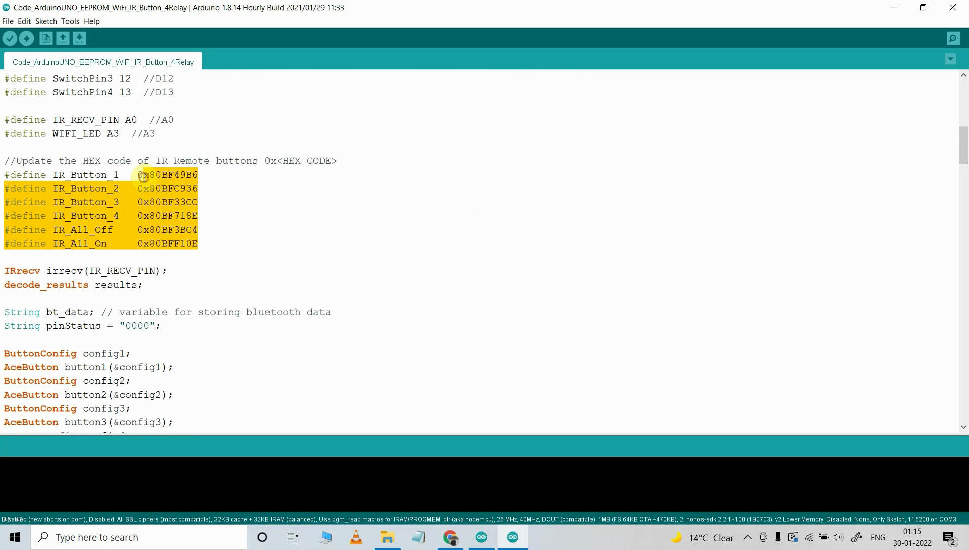
For the main sketch, you need to install following libraries
Then you have to update the HEX code in the sketch for IR remote control.
For momentary switch use the code: Code_ArduinoUNO_EEPROM_WiFi_IR_Button_4Relay.ino
and for latched switch use the code: Code_ArduinoUNO_EEPROM_WiFi_IR_Switch_4Relay.ino
Setup the Google Home App
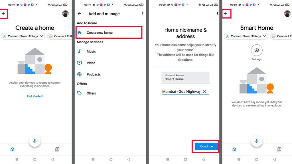
First, download and install the Google Home App. then follow the steps to create Home in Google Home app
- Tap on the "+" icon (upper left corner).
- Tap on Create new home.
- Enter the Home nickname and address.
- Then click on Continue.
The Home is created. Now again tap on the "+" icon to add devices.
Connect Sinric Pro With Google Home App | Add Devices
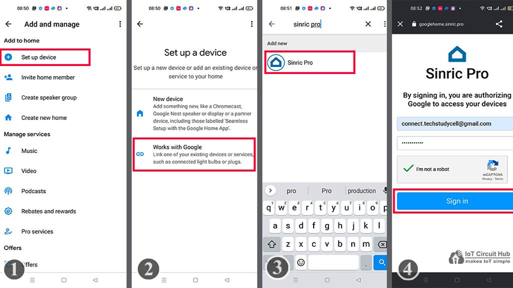
After creating the Home in the Google Home app, you can connect the Sinric Pro with the Google Home app
- Tap on the "+" icon, then select Set up device.
- Tap on Works with Google.
- Search for Sinric Pro, then select Sinric Pro.
- Enter the email id and password used for the Sinric account,
- Then tap on Sign in.
Thus, all the devices from Sinric Pro will be added to Google Home Account.
Configure the Alexa App for This Smart Home System
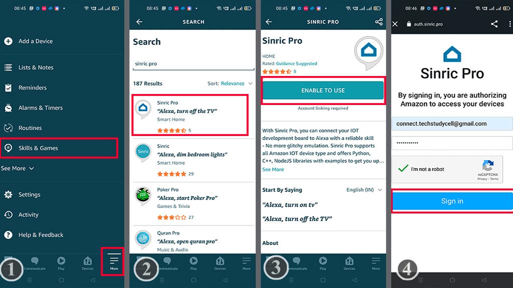
Download and install the Amazon Alexa App from the Google play store or App Store.
- Go to "More", then select "Skills & Games".
- Search for Sinric Pro and tap on "Sinric Pro".
- Tap on "ENABLE TO USE".
- Log in with the Sinric account credentials.
Connecting Devices With Alexa
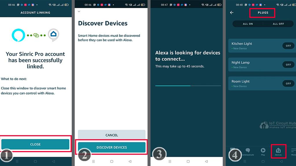
- Tap on CLOSE.
- Tap on "DISCOVER DEVICES".
- It will take a minute to add devices. During this time the ESP-01 should be connected with the WiFi.
- Tap on "Devices", and tap on "Plug" to see all the devices.
Thus, all the devices from Sinric Pro will be added to Amazon Alexa App.
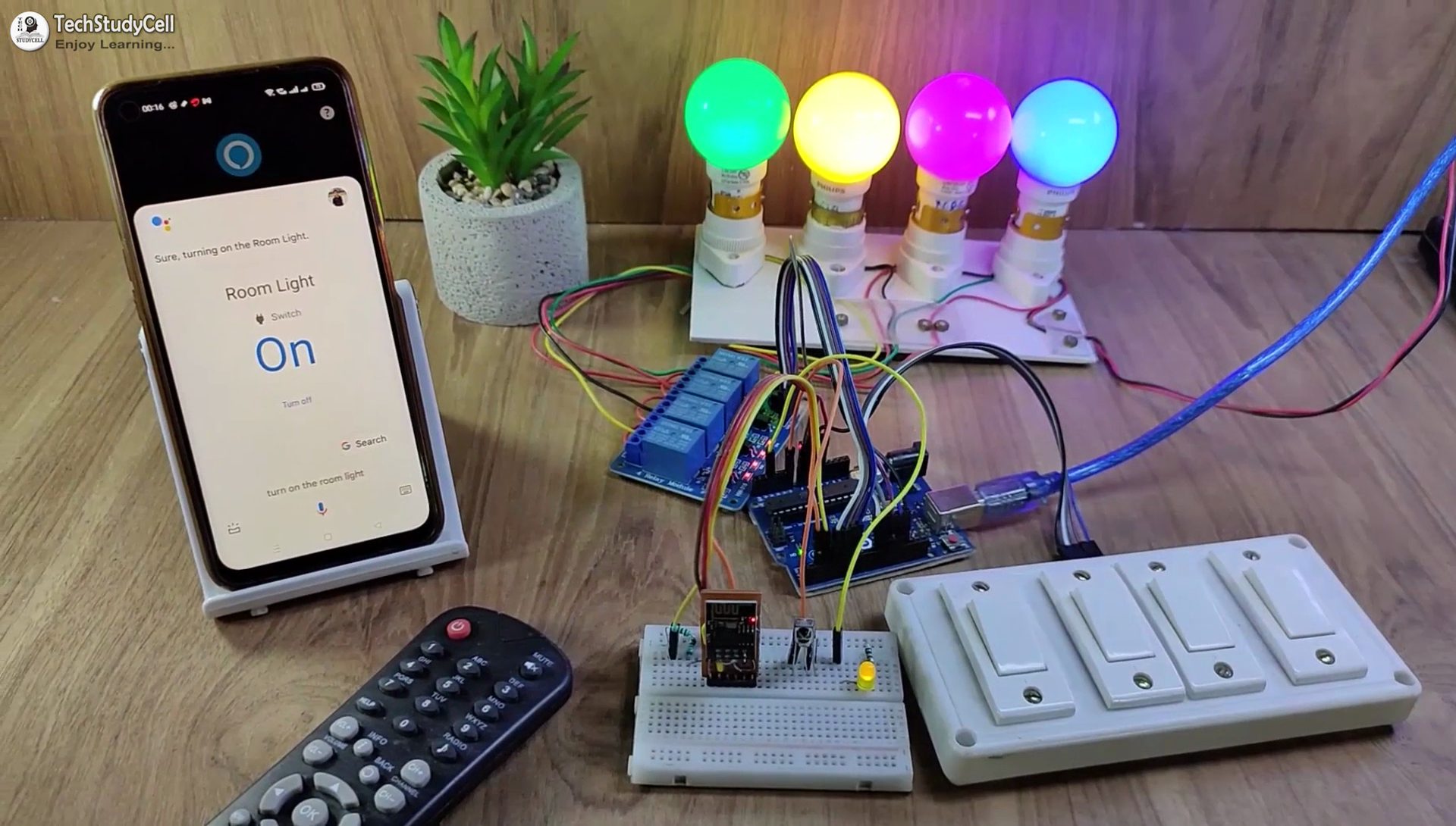
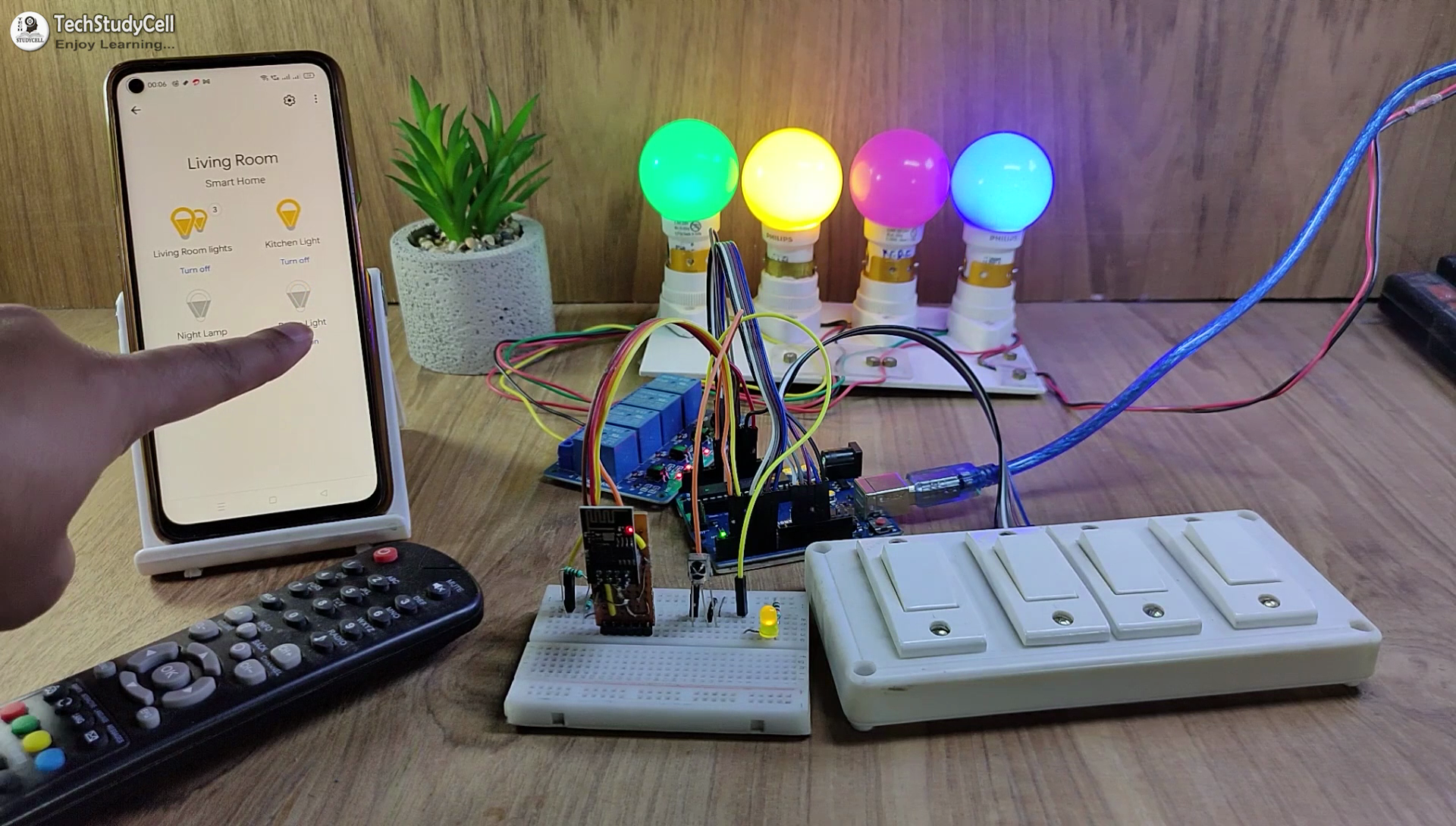
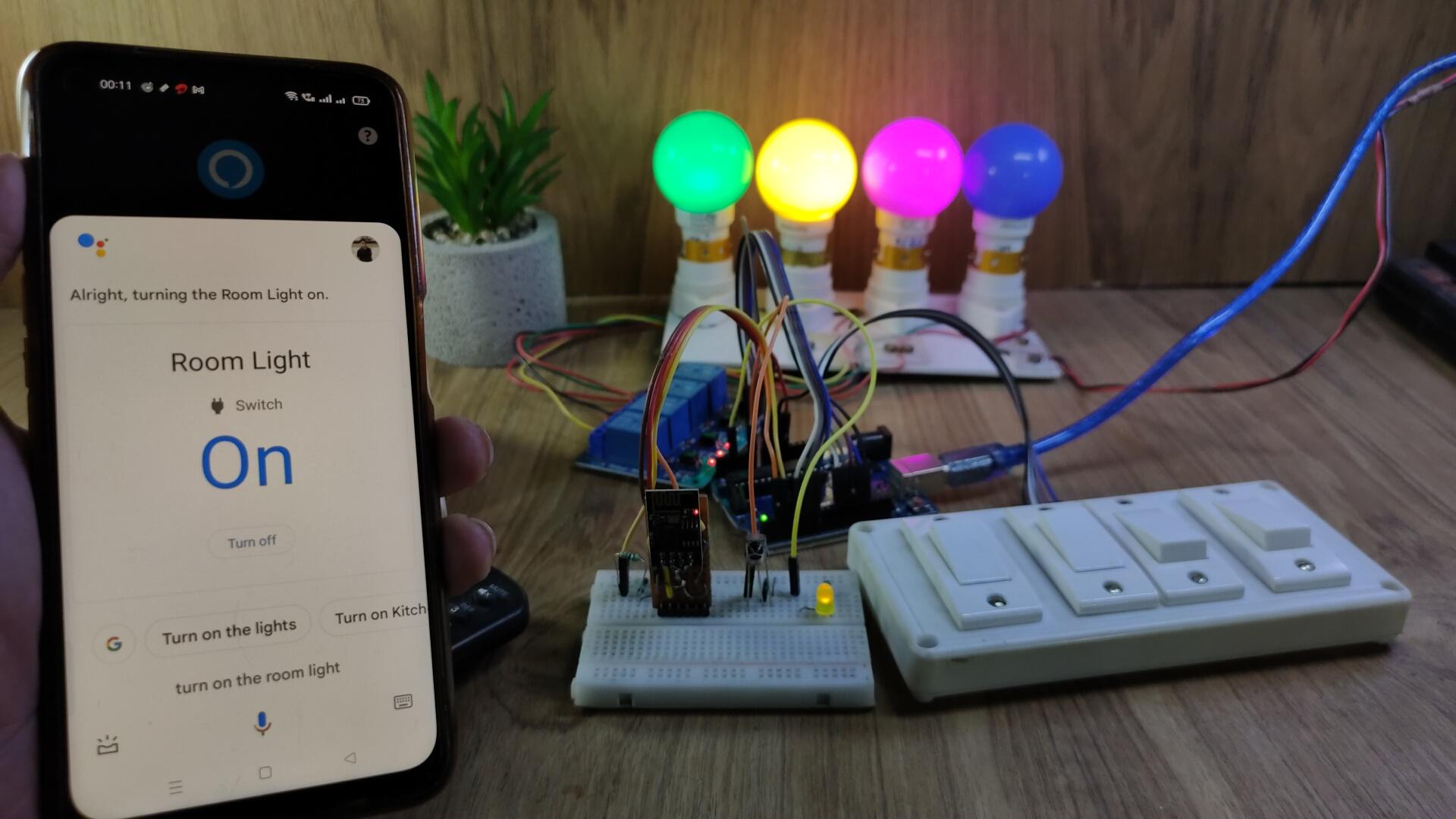
Controlling Relays With Google Assistant and Google Home
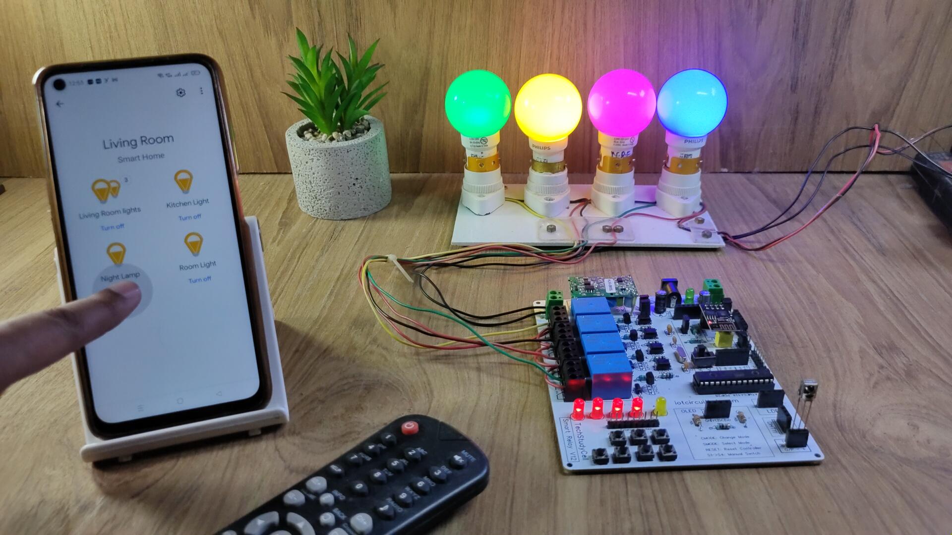
If the ESP01 is connected with the WiFi, then you can control the home appliances from Google Home App.
You can also ask Google Assistant to turn on and off the appliances.
You can control, monitor the real-time status of the relays in the Google Home App from anywhere in the world.
You don't need any Google Home Nest device for this home automation project.
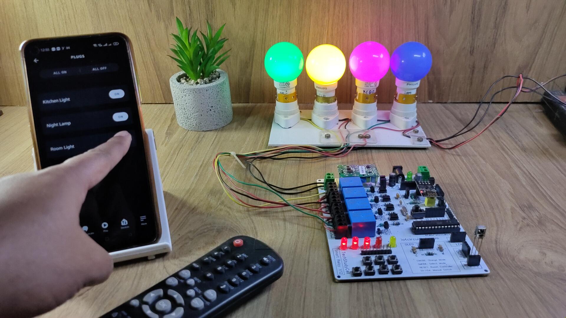
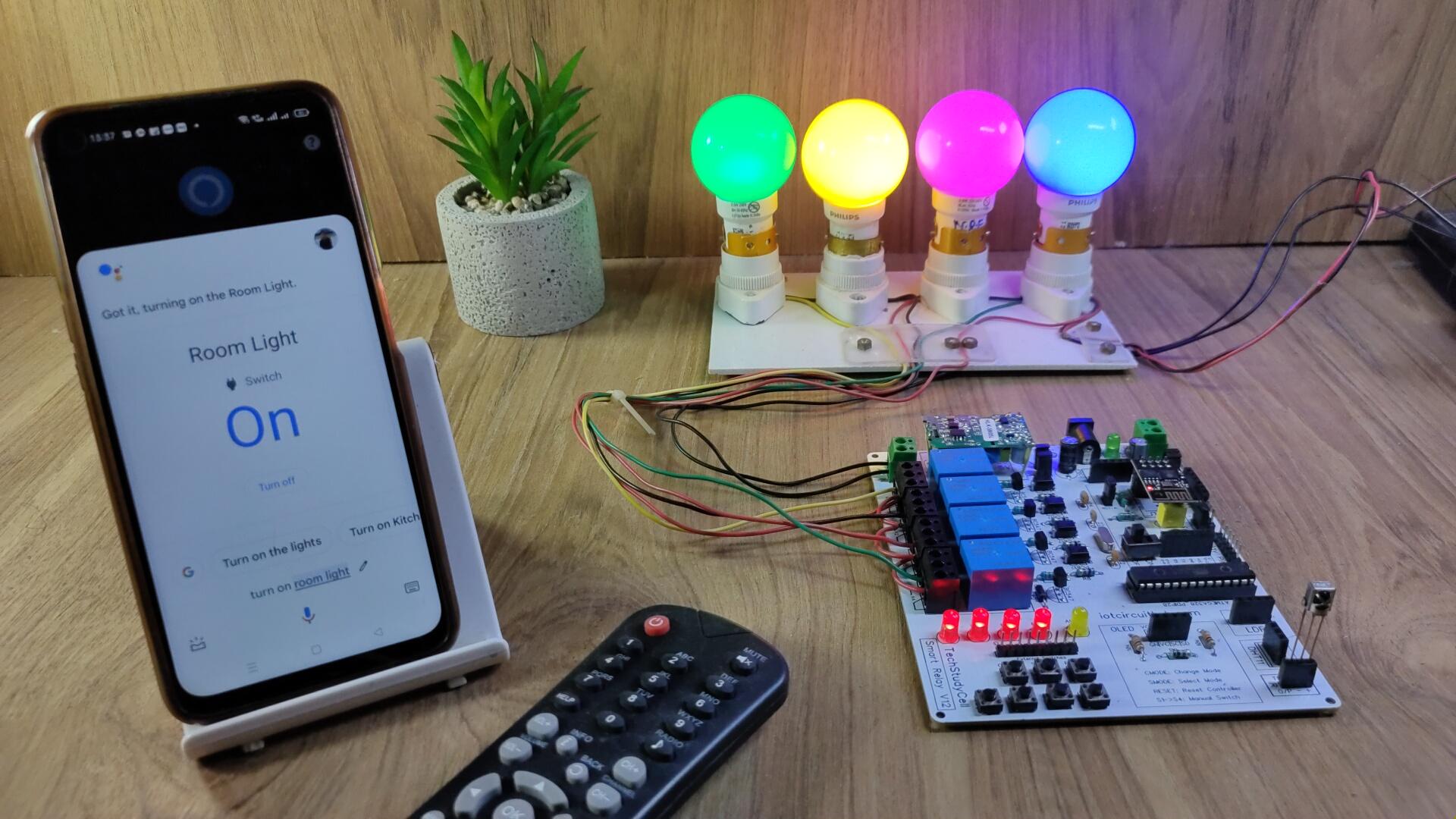
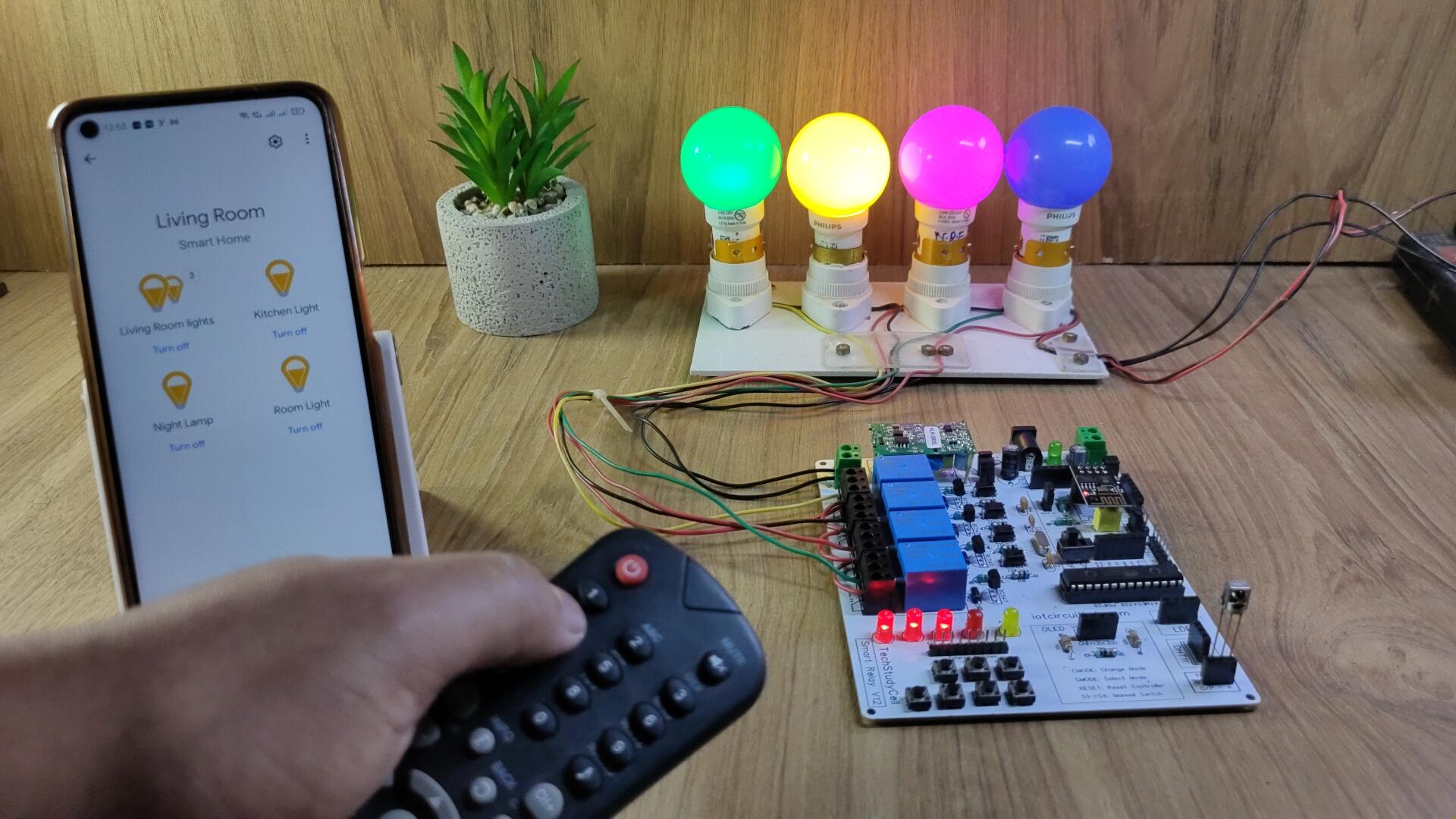
Controlling Relays With Alexa

You can also control the home appliances from Amazon Alexa App if the ESP01 is connected with the WiFi.
You can also ask Alexa to turn on and off the appliances.
You can also control the appliances from the manual switches or IR remote and monitor the real-time feedback of the relays in the Amazon Alexa App from anywhere in the world.
You don't need any Echo DOT device for this home automation project.
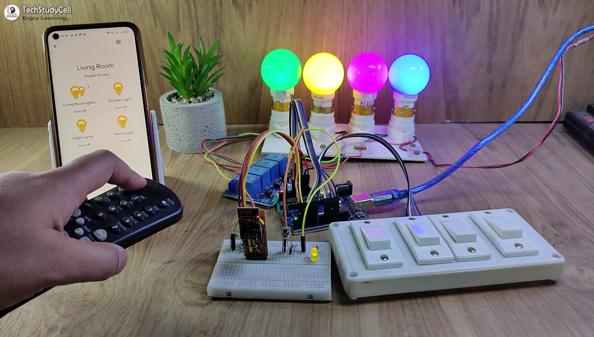
Controlling Relays Manual Switches & IR Remote
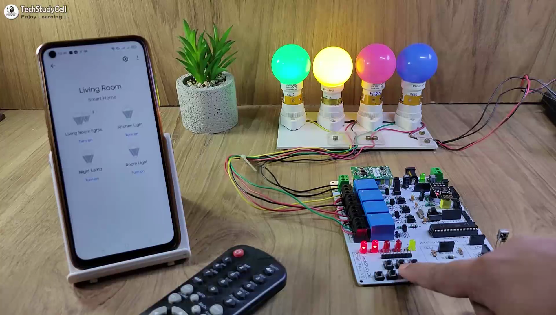
If the WiFi is not available, you can control the relays from the manual switches or IR remote.
The ESP01 will check for the WiFi after every 4 seconds.
When the WiFi is available, the ESP01 will automatically connect with the WiFi.
Please refer to the circuit diagram to connect the manual switches or pushbuttons.
Now you can control your home appliances in a smart way.
I hope you have liked this Google and Alexa control home automation project. I have shared all the required information for this project.
I will really appreciate it if you share your valuable feedback. Also if you have any queries please write in the comment section.
Thank you & Happy Learning.