Arduino Robot


Initial Plan:
I plan to create a robot with shoveling and turning/waving functions.
Features:
Chassis-
- Option 1: Laser cut wooden chassis
- Option 2: 3D printed chassis
Servos-
- Servo 1: Shovel at the front of the robot
- Servo 2: Waving a fitted piece around at the back of the robot
All Processes:
- Wiring
- Chassis
- Servos
- Testing
Supplies


Materials used:
- Wires
- Wood (chassis)
- 3D printing filament (other fitting components)
- Solder
Wiring Components:
- Sensor Shield
- Arduino Uno
- Motor Controller
- Ultrasonic Sensor
- 2 Servos
- 2 Motors
- 2 Wheels
- Battery Pack (holds the batteries in place)
- Battery Pack Brackets (attaches to the battery pack)
- Bluetooth Clip
- USB A to B cable
Assembly
- Screws or additional 3D printed parts for assembly
Tools/Resources used:
Measuring:
- Calipers (precise measurements for fitting pieces together)
- Rulers (approximate measurements)
Wiring:
- Wire Cutter
- Soldering Iron
- Screwdrivers (keeping the wires in place)
- Voltmeter (testing wire connections)
3D Printing:
- Sanding tools
- Glue or Tape (makes the filament stick to the surface)
Assembly:
- Hot glue gun
Programs:
- Adobe Illustrator (designing)
- Autodesk Fusion 360 (3D printed, assembly)
- Creality Print (slicing software for 3D printing)
- Arduino IDE (programming software)
- Dabble App (connecting the programmed robot to a gamepad via Bluetooth)
Other Resources:
- Soldering (strengthening wire connections)
- Library of Robot Resources (extra information and guides)
Wiring- Arduino Sensor Shield


Align the Sensor Shield onto the Arduino Uno.
Wiring- Connecting the Power Switch


Attach the Battery Pack Brackets to the Battery Pack.
Use the wires of the Battery Pack Brackets to connect the power switch to the Motor Controller. Additional wires can be used to extend their length either through twisting the wires together or through soldering. Soldering can be used to strengthen the connection of the wires if needed.
Wiring- Connecting It to the Arduino Sensor Shield


Connect the wires to the correct terminals on the Arduino Sensor Shield.
Red wire- Vin terminal
Black wire- GND terminal
Wiring- Arduino Sensor Shield


Use 4 wires and connect them to the 4 pins on the motor controller. Then connect them to the white terminal pin on the Arduino Sensor Shield on pins 3, 5, 6, 11.
Wiring- Connecting Bluetooth


Use 4 Bluetooth wires and connect them to the COM terminals on the Arduino Sensor Shield.
Note: Notice the order of the wires
These wires can later be connected to the Bluetooth Clip when your robot is functioning.
Wiring- Motors

.png)
Connect the motor wires of the 2 Motors to their respective screw terminals on the Motor Controller. Use a screwdriver to set them in place.
Additional wires can be used to extend their length either through twisting the wires together or through soldering. Soldering can be used to strengthen the connection of the wires if needed.
If the wheels spin the opposite direction, flip the terminals of the wires.
Attach the Motor Wheels to the Motors.
Wiring- Servos


Connect the Servo wires onto the specified spots.
Additional- Testing

Refer to the Testing Process.
Testing is used to ensure that the wired components are all functioning properly.
If working properly, the Bluetooth Clip, the Arduino Sensor Shield and the Motor Controller should all light up.
Test for working Motors and Servos.
Chassis- Sketch and Design

.png)
.png)
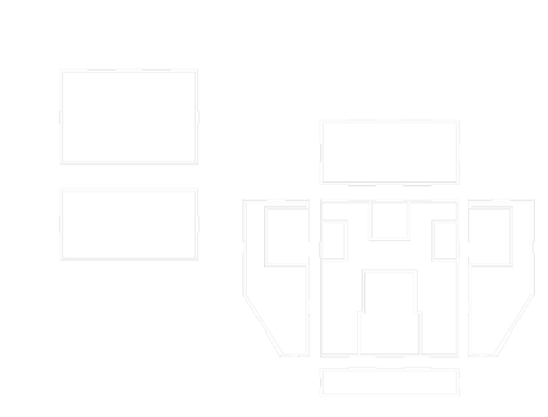
Plan out possible ideas for a chassis and design the chassis in Adobe Illustrator.
A ruler can be a useful tool for determining the size of your chassis.
Create finger joints with the thickness of the wood in mind (3mm).
Chassis- Digital Assembly
.png)
.png)
Assemble the pieces in Autodesk Fusion 360 to ensure that all pieces are being fitted properly.
Section Analysis is a useful tool to ensure that pieces are fitted as desired.
Note: Autodesk Fusion 360 may resize the Adobe Illustrator svg file. The scaling factor is the desired measurement divided by the resized measurement in Autodesk Fusion 360.
Add any corrections needed to the design and assembly digitally in Autodesk Fusion 360 until all pieces are working as desired.
Chassis- Create


Create your chassis.
Servos- Sketch and Design


Plan out the functions for your servos and their parts and design them in either Adobe Illustrator or Autodesk Fusion 360.
Servos- Create


Create your servos parts.
Testing- Completing the Robot

Unzip the downloaded code file and add the Dabble library. Select the right board and port.
Download the code into Arduino IDE after plugging the USB A to B cable into a computer. It can be helpful to unplug the Bluetooth Clip during this process if there are difficulties successfully downloading the code to the Arduino.
If the code is downloaded, it will say "avrdude done. Thank you."
Then connect the robot to the Dabble app via the Bluetooth clip.
Test for working Motors and Servos.
Conclusion

Next time if I had more time, I would like to add the following characteristics to my robot:
- LED features
- Ultrasonic sensor functions (lighting up or activating/deactivating Servos)
- Laser cut my chassis
- Add engravings to my chassis
- Design a more complicated chassis model
- Design more complicated servo functions and parts
- Increase the amount of servos used in my robot
- Add my own code to the Arduino robot to personalize it
- Soldering in order to strengthen my wiring connections