Arduino Remote Controlled Stepper Motors
by dcaditz in Circuits > Arduino
5241 Views, 7 Favorites, 0 Comments
Arduino Remote Controlled Stepper Motors

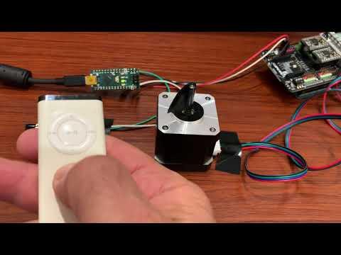
Using an IR remote control, such as an Apple remote or similar device, to control stepper motors is attractive for several reasons, not the least of which is that it eliminates wires between the user and hardware platform. There are many online tutorials demonstrating the use of IR remote controls to control stepper motors. However, because the Arduino's architecture is based on a single-thread central processing unit, these tutorials are often limited to 'canned' motions. For example, pressing a button on the remote produces 10 clockwise steps. Another button produces 100 clockwise steps. A third button produces 10 counter-clockwise steps, etc. This is not an ideal solution for applications that require real-time control. For example, controlling a telescope drive requires that the user line up the scope on a planet or star, which would be difficult with pre-programmed steps.
The source of the problem is that reading and decoding an IR remote command typically takes about 100ms, and during this time the stepper motor control code is blocked and the steppers cannot move. Likewise, when the steppers are moving, the IR Remote code is blocked and commands cannot be read by the Arduino. Even if the motor step commands are placed in a timer ISR, the interrupt may occur in the middle of receiving an IR signal, and the command will be corrupted.
To overcome these issues and to allow full real-time control over the stepper motors, I use two Arduinos: One is a dedicated IR Remote Handler that receives and interprets commands sent from the IR remote control. The other is a dedicated Stepper Motor Controller that sends step commands to one or more motors connected to a stepper motor driver shield. The two Arduinos communicate using I2C, which is much faster than IR protocols allowing full, real time control of the stepper motors.
Supplies
- Arduino Uno
- Arduino Nano (or other Arduino version)
- Stepper Motor driver ( dfrobotics DRI0023 or similar)
- Stepper motor(s)
- Apple IR Remote (other remotes can also be used with slight modification to the code)
- IR receiver TSOP38238 or similar (e.g., this one)
- Power supply for stepper motors (e.g., 12V lead acid battery or 12V DC 2 amp power supply)
- Jumper wires
Timing and Program Archirecture
I want to run my stepper motors at a nominal rate of 200 steps/sec. At this rate, my controller has 5 milliseconds to command each step. In between each step it has to perform other functions such as checking the I2C interface for a new command, checking end stop conditions if needed, etc. The stepper motor driver board that I am using is based in a TI DRV8825 Stepper Motor Controller IC (https://www.ti.com/lit/ds/symlink/drv8825.pdf). The data sheet calls for a minimum step command time of about 4 μs (2 μs high and 2 μs low). If I very conservatively allocate 50 μs for the step command, then there will be 4.5 ms between steps for other functions. As mentioned earlier, reading an IR remote signal takes about 100 ms, so this is out of the question. However, I2C data rates are 100 kbps or higher, meaning that one byte of data can be sent in less than 1 ms, which, even including overhead, should be fast enough to read and process between 5 ms steps. This is the motivation for having separate dedicated IR Remote Handler and Stepper Motor Driver Arduinos that communicate using I2C.
The Stepper Driver Arduino is designated as I2C Master and the IR Remote Handler is designated as I2C slave. The Stepper Driver Arduino uses an interrupt service routine (ISR) to command each step. The main loop polls for I2C data from the IR Remote Handler and sets flags used by the ISR to control the steppers. Using an ISR, as opposed to putting step control in the loop, guarantees that the stepper motor will run smoothly, with accurately timed step signals. So long as the loop runs at least once between steps we are guaranteed to have real-time control.
Setting Up the IR Remote Handler

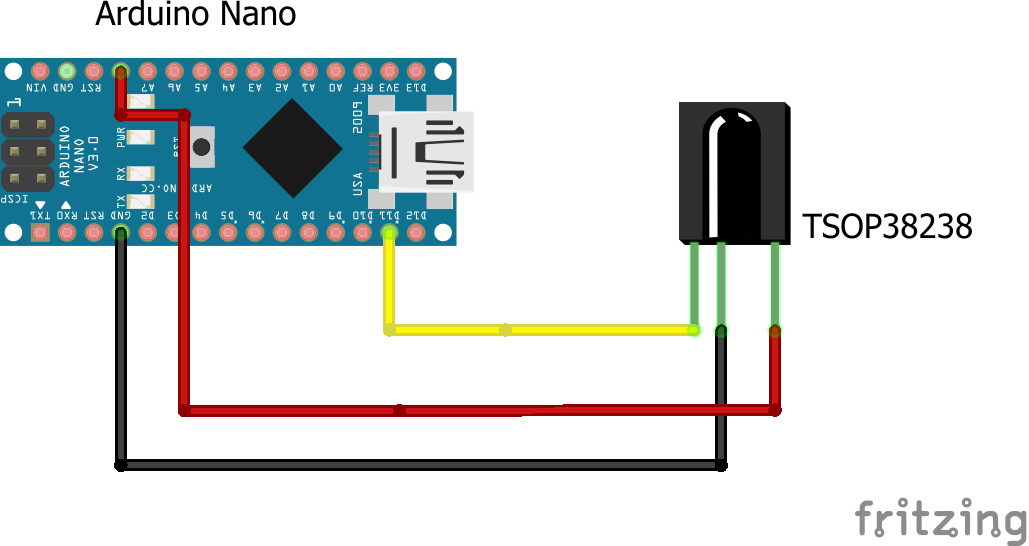
Connect your TSOP23838 IR receiver to the Nano (or other Arduino...I just happened to have a Nano) as shown in the diagram. You can inspect the TSOP23838 datasheet here.
Now, fire up your Arduino IDE and start a new file. Select Tools->Manage Libraries and in the search field type "IRremote". Install the IRremote library by shirriff. The latest version at the time of writing this Instructable is v.2.8.0. This library is being actively maintained and there may be some changes in later versions. Read through the release notes for necessary code modifications if you have a later library version.
Once the library is installed you will see several example sketches in File->Examples->IRremote. Open up the IRreceiveDemo example sketch. Now upload and run the IRreceiveDemo sketch and open the serial monitor to view the results. If things are working you should see something like the following:
START C:\[YOUR_FILE_PATH]\IRreceiveDemo.ino from Jan 21 2021
Enabling IRin
Ready to receive IR signals at pin 11
Protocol=NEC Data=0x77E15061
Protocol=NEC Data=0x77E13061
Protocol=NEC Data=0x77E16061
Protocol=NEC Data=0x77E19061
Protocol=NEC Data=0x77E1A061
Protocol=NEC Data=0x77E1C061
The last 6 lines are responses to my clicking the Apple remote up, down, left, right, center, and menu buttons in that order. (If your remote has more buttons, you can also click them and view their codes.)
You may also see lines like the following:
Protocol=NEC Data=0xFFFFFFFF
These are repeated signals from the remote due to pressing the button longer than about 100ms, which is how long it takes to receive and decode the IR signal from a single button click.
Now we know how to detect remote control clicks in our main sketch. (This procedure should work with any IR remote control to detect button codes, not just the Apple version.) If things are not working as expected, check the TSOP38238 wiring and also make sure your remote control battery is not dead!
Now we can load the IR Remote to I2C code to program the IR Remote Handler :
/*<br>// Receive and decode signal from IR remote.<br>// Functions as I2C slave<br>// Sends one byte signal to I2C master<br>// apple_left = 'l'<br>// apple_right = 'r'<br>// etc.<br>*/<br><br>#include <IRremote.h><br>#include <Wire.h><br><br>// IR commands for apple remote (last two digits truncated )<br>#define apple_left 0x77E190 //7856528<br>#define apple_right 0x77E160 //7856480<br>#define apple_up 0x77E150 //7856464<br>#define apple_down 0x77E130 //7856464<br>#define apple_center 0x77E1A0 //7856544<br>#define apple_menu 0x77E1C0 //7856576<br>#define apple_repeat 0xFFFFFF // 16777215<br><br>int IR_RECEIVE_PIN = 11; // D11 for Uno, Nano<br>IRrecv IrReceiver(IR_RECEIVE_PIN);<br>uint32_t last_command = 0;<br>char I2C_command = 'x';<br><br>void setup() {<br> Wire.begin(8); // join i2c bus with address #8<br> Wire.onRequest(requestEvent); // register event<br> Serial.begin(9600);<br> Serial.println("Enabling IRin");<br> IrReceiver.enableIRIn(); // Start the receiver<br> IrReceiver.blink13(true); // Enable feedback LED<br>}<br><br>void loop() {<br> if (IrReceiver.decode()) {<br> if (IrReceiver.results.decode_type == NEC) { //Apple remote is decoded as NEC<br> if ( IrReceiver.results.value / 256 == apple_repeat) { // divide by 256 to truncate last two digits<br> if (last_command == apple_left || last_command == apple_right || last_command == apple_up || last_command == apple_down ) {<br> IrReceiver.results.value = last_command * 256; // We want to be able to send repeated directional commands.<br> }<br> }<br><br> switch (IrReceiver.results.value / 256) { // need to remove last 2 decimal places because different remotes give different values.<br> case apple_left:<br> Serial.println("apple_left");<br> I2C_command = 'l';<br> last_command = apple_left;<br> break;<br> case apple_right:<br> Serial.println("apple_right");<br> I2C_command = 'r';<br> last_command = apple_right;<br> break;<br> case apple_up:<br> Serial.println("apple_up");<br> I2C_command = 'u';<br> last_command = apple_up;<br> break;<br> case apple_down:<br> Serial.println("apple_down");<br> I2C_command = 'd';<br> last_command = apple_down;<br> break;<br> case apple_center:<br> Serial.println("apple_center");<br> I2C_command = 'c';<br> last_command = apple_center;<br> break;<br> case apple_menu:<br> Serial.println("apple_menu");<br> I2C_command = 'm';<br> last_command = apple_menu;<br> break;<br> case apple_repeat:<br> Serial.println("apple_repeat");<br> //I2C_command = 'x';<br> last_command = apple_repeat;<br> break;<br> default:<br> Serial.println("default");<br> //I2C_command = 'x';<br> last_command = 0;<br> break;<br> }<br><br> } else {<br> Serial.println("Unknown protocol");<br> //I2C_command = 'x';<br> last_command = 0;<br> }<br> IrReceiver.resume(); // Enable receiving of the next value<br><br> }<br><br>}<br><br>// This function executes whenever data is requested by master<br>// It is registered as an event in setup()<br>void requestEvent() {<br> Wire.write(I2C_command); // respond with message of 1 byte as expected by master<br> I2C_command = 'x'; <br>}<br>Setting Up the Stepper Driver

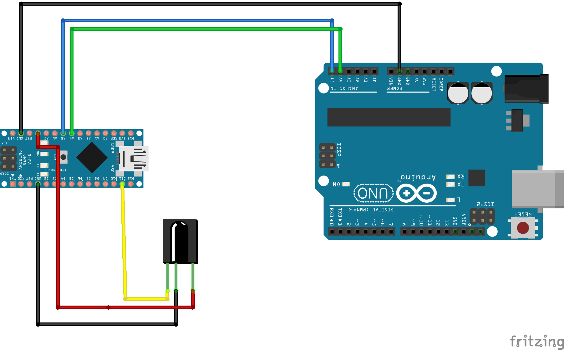
Now we add the Arduino Uno as Stepper Motor Driver/ I2C Master device. Connect the I2C bus (Ground, SDA, SCL) to the I2C slave device as shown in the image. (The stepper motor shield and motor(s) are not shown.) The code for the Stepper Motor Driver is below. This sketch is designed for a dfrobotics DRI0023 stepper motor driver board, however, it can easily be modified for another shield by modifying the pin mappings for direction, step and enable pins.
Steps are generated in the ISR on TIMER1. If M1step = 1, then a step is commanded on motor 1. Likewise for motor 2 if you have dual motors. The step_mode parameter determines whether the system is in single step (0) or continuous step (1) mode. The mode is toggled by an I2C command 'm' generated by pressing the menu button on the Apple remote. If step_mode = 0, then MXstep is set to zero after one step and a second button press will be required to generate an additional step. If step_mode = 1, then a single press will cause the motor to step continuously until a 'c' (Apple remote center button) command is received. Depending on your application, you might want to implement some end stop detectors.
Once the code is uploaded to the Stepper Motor Driver/ I2C Master device, you can install your stepper motor driver shield, stepper motor(s) and motor power supply and enjoy your real time IR Remote controlled stepper motor system!
#include <Wire.h><br><br>// dfrobotics DRI0023 stepper motor driver board:<br>const int M1dirpin = 4;<br>const int M1steppin = 5;<br>const int M1en = 8; //Motor X enable pin () Some versions of DRI0023 do not use enable pins<br>const int M2dirpin = 7;<br>const int M2steppin = 6;<br>const int M2en = 12; //Motor Y enable pin<br>int M1step = 0;<br>int M2step = 0;<br>int M1dir = 1;<br>int M2dir = 1;<br>int step_mode = 0; // single step or continuous stepping<br>int Mfreq = 200; // step frequency in Hz for continuous stepping<br><br><br>void setup() {<br><br> pinMode(M1dirpin, OUTPUT); //Direction pin for motor driver 1<br> pinMode(M1steppin, OUTPUT); // Step pin for motor driver 1<br> pinMode(M1en, OUTPUT); // Enable pin for motor driver 1<br> pinMode(M2dirpin, OUTPUT); //Direction pin for motor driver 2<br> pinMode(M2steppin, OUTPUT); // Step pin for motor driver 2<br> pinMode(M2en, OUTPUT); // Enable pin for motor driver 2<br><br> Wire.begin(); // join i2c bus<br> // Serial.begin(9600); // We want to minimize the number of Serial Monitor swites to keep motors running smoothly<br><br> // initialize TIMER1 for stepper motor<br> noInterrupts();<br> TCCR1A = 0;<br> TCCR1B = 0;<br> TCNT1 = 0;<br> OCR1A = round(16000000 / 256 / Mfreq); // compare match register 16MHz/256/Step Frequency<br> TCCR1B |= (1 << WGM12); // CTC mode<br> TCCR1B |= (1 << CS12); // 256 prescaler<br> TIMSK1 |= (1 << OCIE1A); // enable timer compare interrupt<br> interrupts(); // enable all interrupts<br><br> digitalWrite(M1en, LOW); // Low Level Enable<br> digitalWrite(M2en, LOW ); // Low Level Enable<br><br>}<br><br>void loop() {<br> Wire.requestFrom(8, 1); // request 1 byte from slave device #8<br> while (Wire.available()) { <br> char c = Wire.read(); // receive a byte as character<br> // Serial.println(c);<br> switch (c) { // need to remove last 2 decimal places because different remotes give different values.<br> case 'x':<br> break;<br> case 'l':<br> M1step = 1;<br> M1dir = -1;<br> break;<br> case 'r':<br> M1step = 1;<br> M1dir = 1;<br> break;<br> case 'u':<br> M2step = 1;<br> M2dir = 1;<br> break;<br> case 'd':<br> M2step = 1;<br> M2dir = -1;<br> break;<br> case 'c':<br> M2step = 0;<br> M1step = 0;<br> digitalWrite(M1en, HIGH); // Disbale motor to save energy<br> digitalWrite(M2en, HIGH ); // Disbale motor to save energy<br> break;<br> case 'm':<br> step_mode = (step_mode == 0) ? 1 : 0;<br> delay(500); // delay to avoid double pressing<br> break;<br> default:<br> M2step = 0;<br> M1step = 0;<br> break;<br> }<br> }<br>}<br><br><br><br><br><br>// ----------------------------------------------------------------------------<br>// TIMER ISR FOR DRIVING STEPPER MOTORS<br>// ----------------------------------------------------------------------------<br>ISR(TIMER1_COMPA_vect)<br>{<br> if (M1step == 1) {<br> digitalWrite(M1dirpin, M1dir == 1 ? HIGH : LOW);<br> digitalWrite(M1steppin, HIGH);<br> delayMicroseconds(2);<br> digitalWrite(M1steppin, LOW);<br> delayMicroseconds(2);<br> M1step = step_mode == 0?0:1;<br> }<br><br> if (M2step == 1) {<br> digitalWrite(M2dirpin, M2dir == 1 ? HIGH : LOW);<br> digitalWrite(M2steppin, HIGH);<br> delayMicroseconds(2);<br> digitalWrite(M2steppin, LOW);<br> delayMicroseconds(2);<br> M2step = step_mode == 0?0:1;<br> }<br>}<br>