Arduino Relay Activated Light (TinkerCad)
by 649723 in Circuits > Arduino
6935 Views, 17 Favorites, 0 Comments
Arduino Relay Activated Light (TinkerCad)
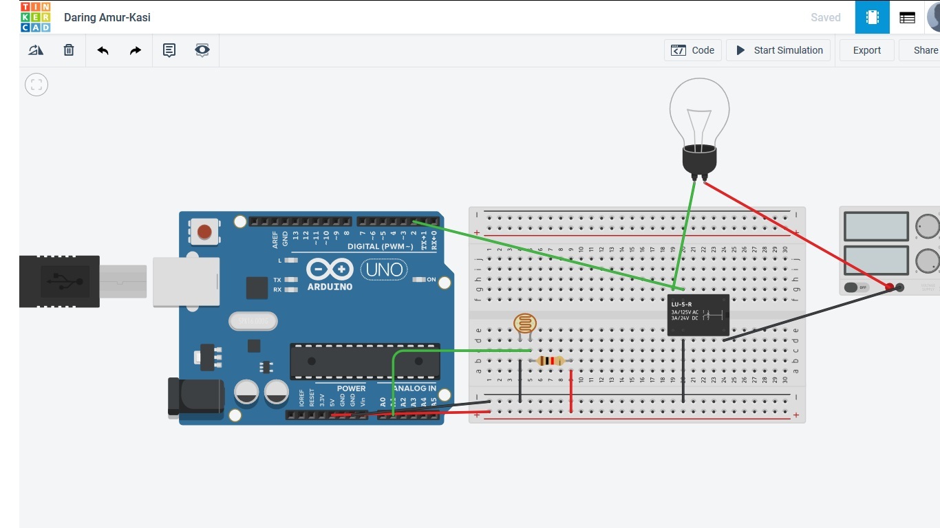
So today we'll be making an Arduino Relay Activated Light on TinkerCad. If you already have a TinkerCad account then that's great but if you don't then you'll need to make an account. Since TinkerCad is a free simulation application you don't need any real materials but these are the supplies you'll need from TinkerCad.
Supplies
- LDR (1)
- Arduino microcontroller (1)
- Lightbulb (1)
- Relay (1)
- A power source (1)
- Breadboard (optional) (1)
- A 1000 Ohm resistor (1)
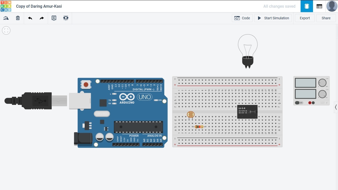
So first what you'll need is to bring out all of your materials and lay them out like this. After we bring out all the required materials what we'll need to do is connect the wires.
LDR
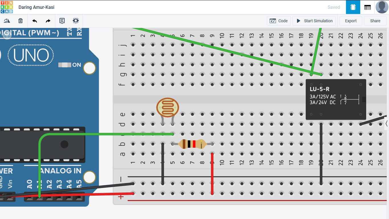
So first what we'll wire is the LDR sensor. We'll have to connect power and ground throughout the breadboard and then connect the LDR to ground, power (with a 1000 Ohm resistor) and connect it to the Arduino with pins A0-A5.
Relay
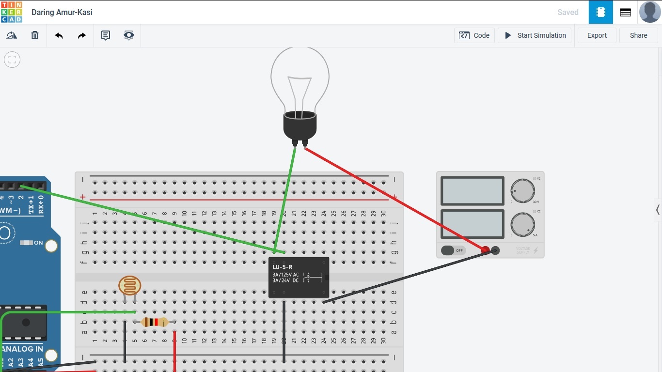
Next what we need to do is connect the lightbulb, power source, relay and Arduino. The relay is important in this circuit because it uses a lower voltage in order to control higher voltage circuits. We connect the power from the power source to the lightbulb, and the ground goes to the relay on terminal 12. The lightbulb gets its power from the power source because the Arduino's 5V is too weak to power it. The ground from the Arduino then goes to terminal 8, with the lightbulb remaining terminal being connected to terminal 6 of the relay. Finally, a digital pin from the Arduino (with no ~ in front of it) will connect to terminal 5. Now we move onto the code.
Void Setup
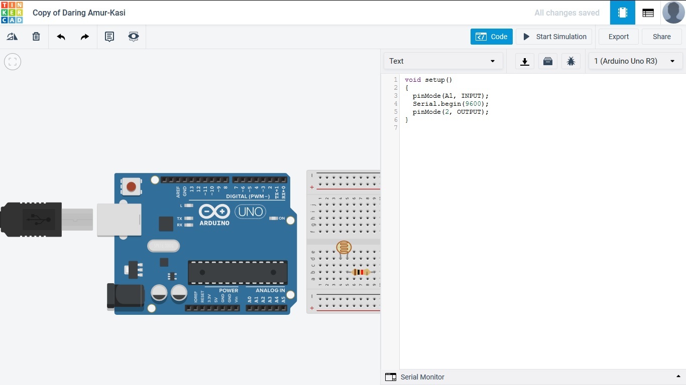
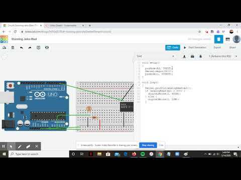
Now once the wiring is done, we have to begin coding. What we need to do is define the pins that we connected the LDR and relay to. We use pinMode and select the pin number, and then chose input or output. For the LDR we would put pinMode (A1, INPUT) because the LDR is used to show how much light is there. For the relay, we would put pinMode (2, OUTPUT) because the output allows the power to be sent to the lightbulb. We also use the Serial.begin(9600) to start the serial monitor, which is used with the LDR. (The pin numbers change based on which ones you connected the LDR and relay to).
Void Loop
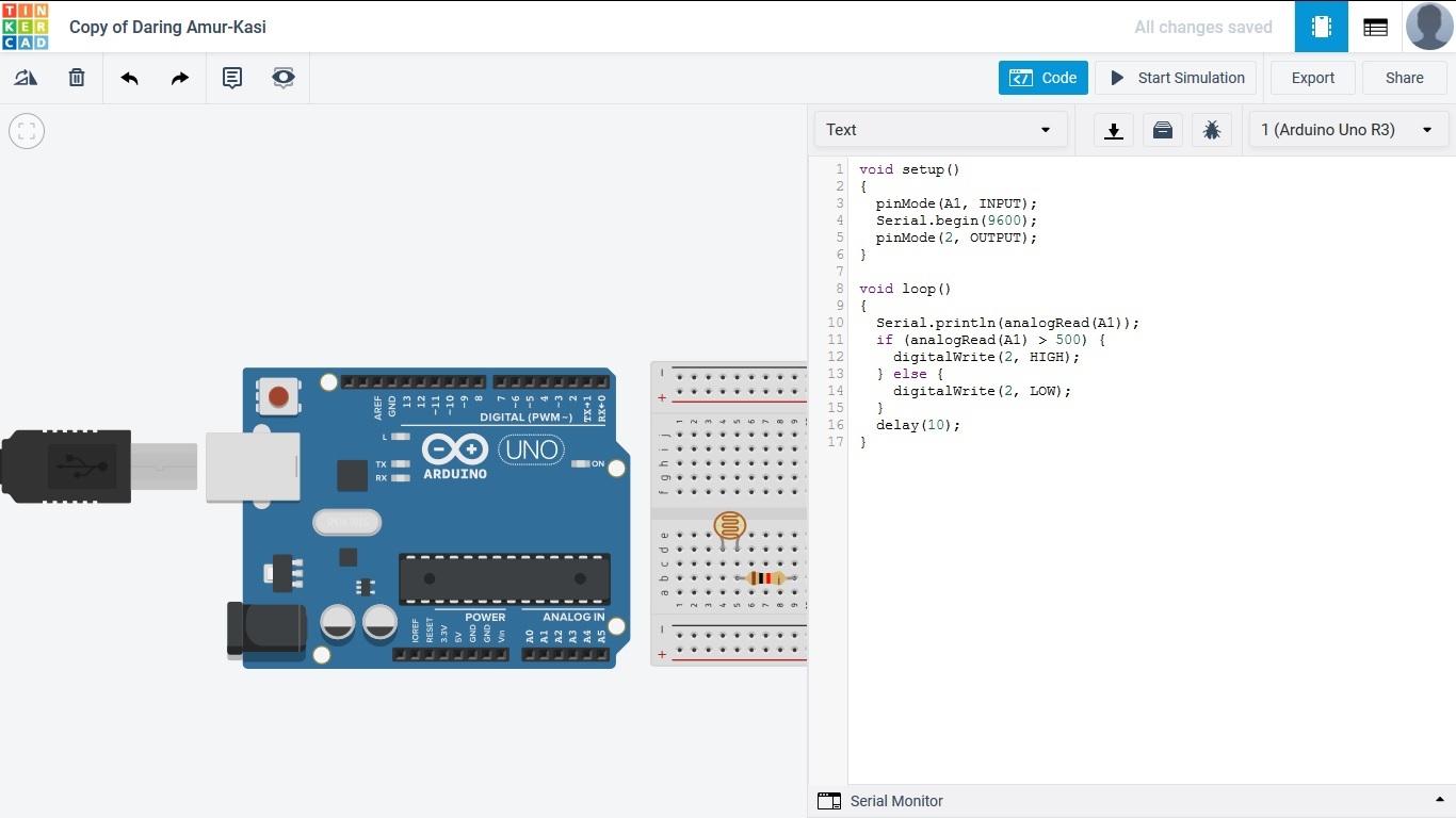
The void loop is the final piece of code used to keep the program working. The first thing to do is use Serial.println(analogRead(A1)); to print the LDR data to the serial monitor. Then what we do is add an if statement. The if statement can be used to turn on the light, and an else statement can be used to turn off the light. The code will be if (analogRead(A1) > 500) {
digitalWrite(2, HIGH);
}
else { digitalWrite(2, LOW); }
This code is telling us that if the LDR produces numbers above 500 (which would mean there's a lack of light) the light will turn on, and if the number in the serial monitor is below 500 (which is an adequate amount of light) the light will turn off. Finally, you can add a delay (10); to the code just so the code runs smoothly.
There you have it guys, the code can also be done with blocks just make sure you remember the pin numbers when coding. I will show the complete code and the making of the circuit in this video just to clear any confusion.
Check Out Videos to Make Sure Everything's Right
