Arduino Relay Activated Lamp
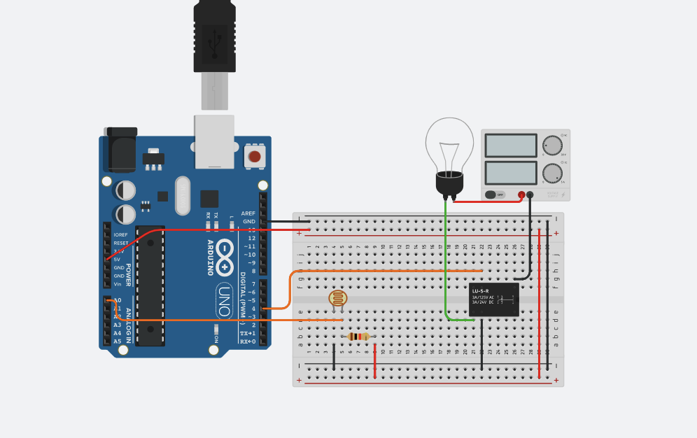
In this project we will be using primarily an Arduino to make a lamp that will only be activated when it's dark! To do this we will be using various electronic components such as a relay and light dependant resistor. The light bulb requires 120 V however the Arduino only proves 5 V, the relay will fix this issue. The light dependant resistors job will be to determine how bright it is, we will use this along with some code to make the light bulb only turn on when it's dark.
Supplies
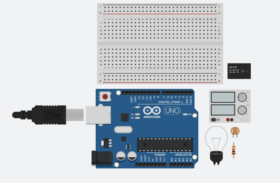
Here are all the supplies you will be needing
- Arduino Uno R3
- Power supply
- Light bulb
- SPDT relay
- light dependant resistor
- 1k ohm resistor
- bread board
- jumper wires
Basic Assembly
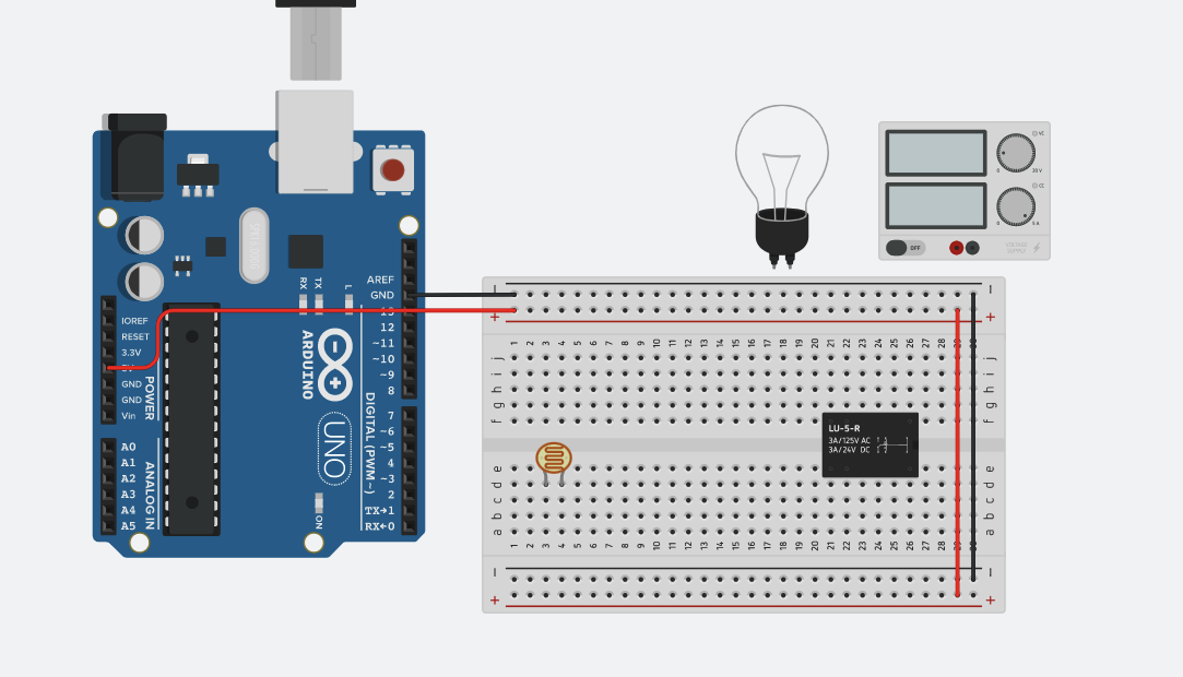
First thing to do is to setup all the basic wiring, such as giving both rails power and ground as well as setting up a few of our pieces such as the relay and light dependant resistor along with the light bulb and power supply.
LDR Assembly
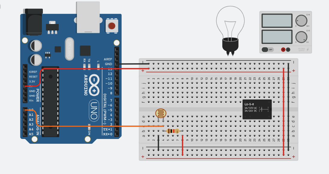
For the LDR connect one leg to ground and the other into power along with the 1k ohm resistor. Also connect the leg with power to Analog 0
Relay/Light Bulb Assembly
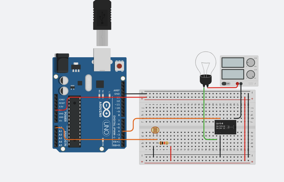
Next up is to assemble the relay. Connect terminal 8 to ground. Connect terminal 5 to port 4 on the Arduino. Connect terminal 7 of the relay to terminal 1 of the light bulb. Connect terminal 1 of the relay to the negative side of the power supply, and then connect the positive side of the power supply to the light bulb. Now your finished with the assembly! Onto the code.
Code
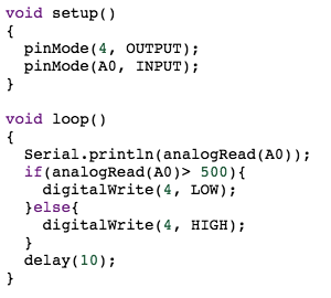
I will go over each part of the code and explain it.
void setup(){
pinMode(4, OUTPUT);
pinMode(A0, INPUT);
}
this part of the code sets pin 4 (our relay) since we will not be needing any input from the relay. It sets pin A0 (our LDR) to input since we will be reading it's signals to determine the amount of brightness.
void loop(){
Serial.println(analogRead(A0));
if(analogRead(A0)> 500){
digitalWrite(4, LOW);
}
else
{
digitalWrite(4, HIGH);
}
delay(10);
}
this part of the code determines wether or not to turn the light bulb on based on the brightness. The first line prints whatever the LDR is determining the brightness to be through the A0 ping. The if statement also reads what the LDR is determining the brightness to be and than if it's greater than 500 set pin 4 (our relay) to low turning the lightbulb, otherwise it's dark and set pin 4 to high turning the light bulb on.
Your Done!
Now you can start your simulation or power your Arduino on and see the light bulb turning off and on based on the brightness. Make sure the power supply stays at roughly 5V.