Arduino Reaction Game
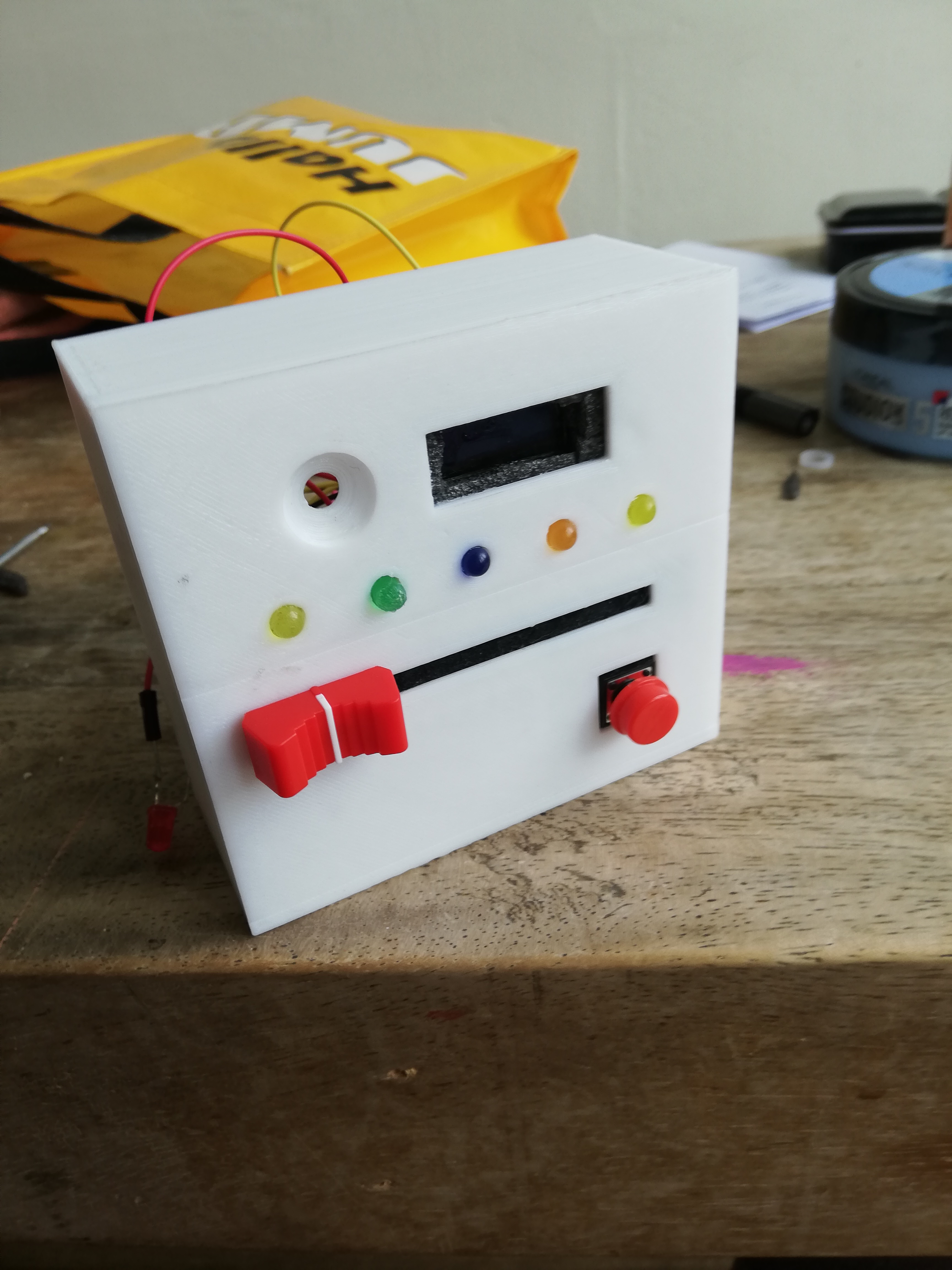
I made this game as a school assignment. We had to make something interactive with an arduino. This is my first Arduino project I've ever made, so it was pretty difficult, but not impossible!
Gathering Your Tools
For this project you'll need:
- Arduino. (I used the nano, but you can use any Arduino)
- slider (potentiometer)
- A button
- LED screen, preferably 32 x 128
- At least six LED lamps (I would recommend getting a bunch of them, they will break easily)
- A breadboard to test your project
- battery holder
- laptop/ computer
- Soldering Iron
Connecting LEDS
When you have gathered all your tools, it's time to make!
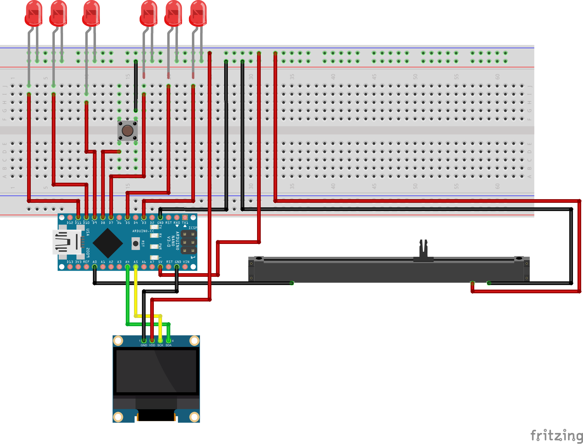
This is the Schematic of the project.
So, how do you do this?
First of all, connect your Arduino to your computer and download the code. Upload it to your Arduino
When you've uploaded the code, get your breadboard out!
Connect your LED lamps as the scheme above, put the litttle string of the LEDS in the ground line on your breadboard (usually it's the blue line on the top side of your breadboard). Get one or your cables and connect it to GND (ground) on your arduino, and the other side on the ground line on the breadboard. Now everything you will put on this whole horizontal line, will be grounded.
The other side of the LEDS should be on the breadboard. You can put them anywhere, as long as you connect them to the digital pins of your Arduino. That way, they will get electricity and you can use them for your code. As for the digital pins: you have five leds, so you're going to connect them all to different digital pins.
Led one should be connected to digital pin 3, led two connected to digital pin 5, led three connected to digital pin 7, led four connected to digital pin 9 and led five connected to digital pin 10. Make sure that you put the cables on the vertical line of your breadboard, and not on the horizontal line.
There is a sixth led, this led is your players "Life lamp", a light that indicates if the player loses or not. This light should be connected in the same way, but uses the digital pin 11.
And that's it for connecting the LEDS!
Downloads
Slider
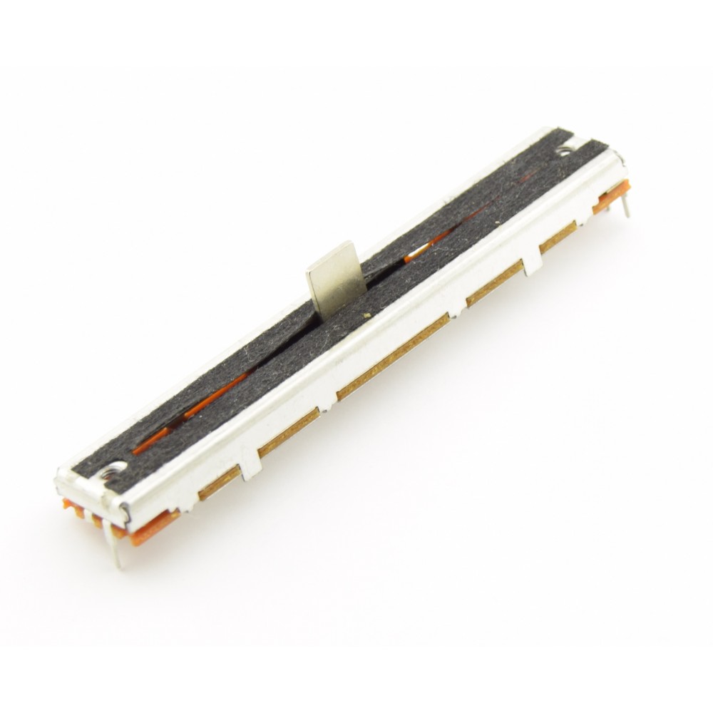
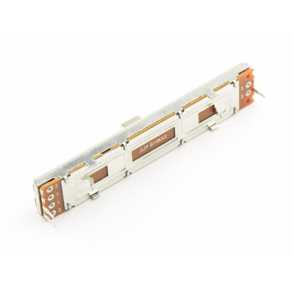
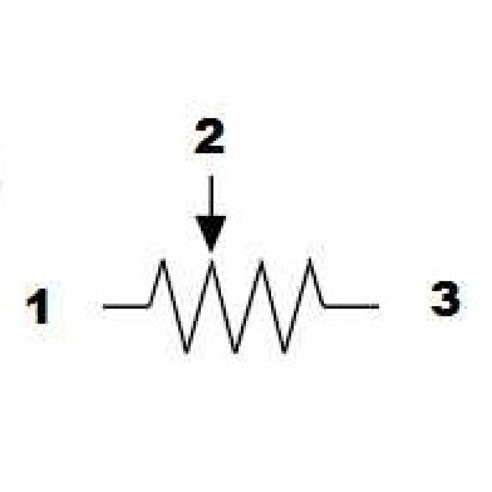
The slider is fairly easy to connect. The slider has 3 pins. The two pins on one side are the ground and volt, the other pin is your signal.
The signal pin goes to the Analog Pin A1
The ground pin goes to ground line on your bread board.
Now, we havent done this yet, but it's also important to make a 5V line on your breadboard. It's either beneath or above the ground line, and it's red. Get your cable and put it in the 5V on your arduino. Put the other line on the 5V line on your breadboard. This whole horizontal line is now your 5V line and you can put all your electricity here.
Put the 5V pin on this line and your slider should be connected!
LED Screen
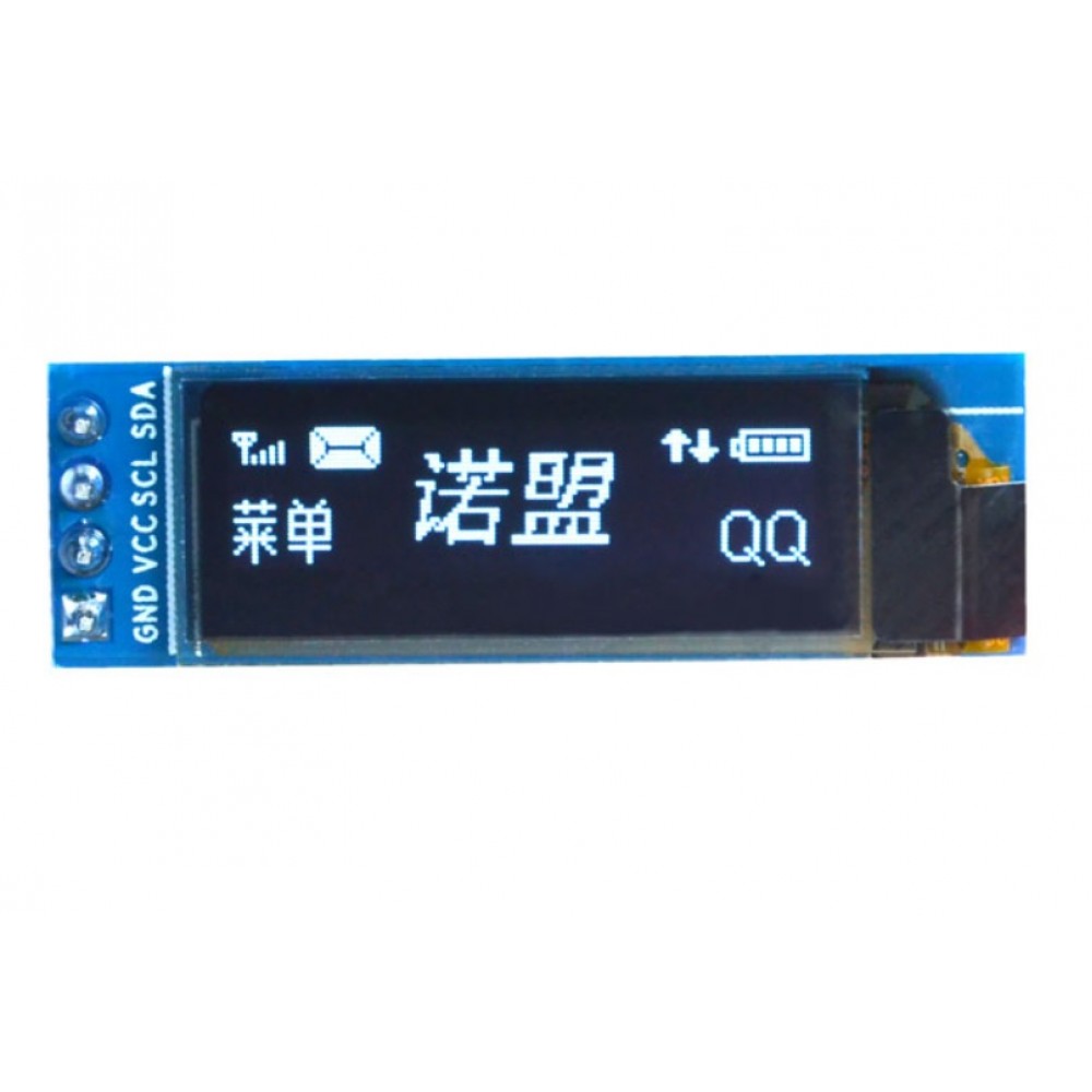
This part of the instruction only works for a 4 pin LED screen on the Arduino Nano. Make sure your screen has these pins: GND, VDD, SCK and SDA. The Arduino Uno has the SCK and SDA switched around, so google this step if you are not sure how to connect your screen.
The GND pin is easy, you connect this to either your ground line on the breadboard, or the remaining ground pin on your arduino.
After that, connect the VDD to your 5V line.
The SCK and SDA use the analog pins 4 and 5, SCK uses Analog pin 5 and SDA uses Analog pin 4.
Now that your screen is connected, put your arduino in your power source and make sure it's working.
Button
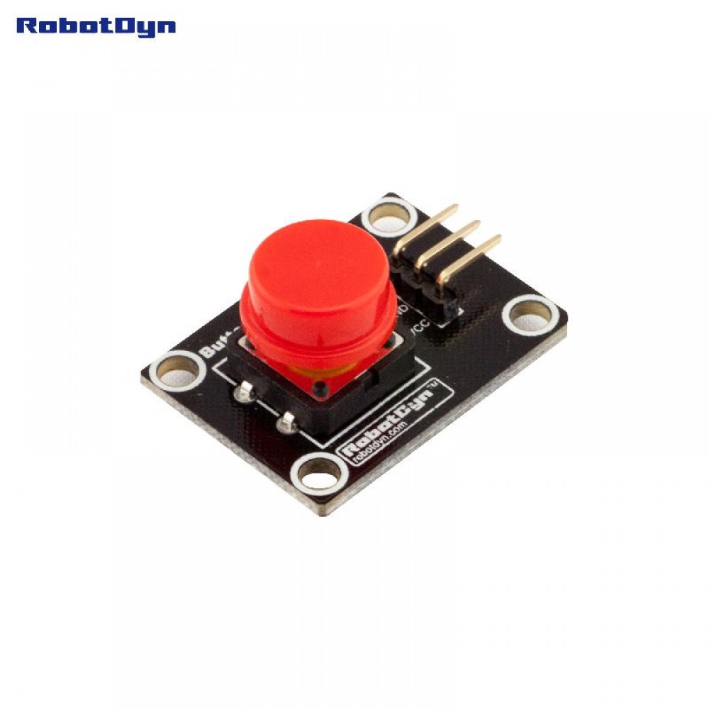
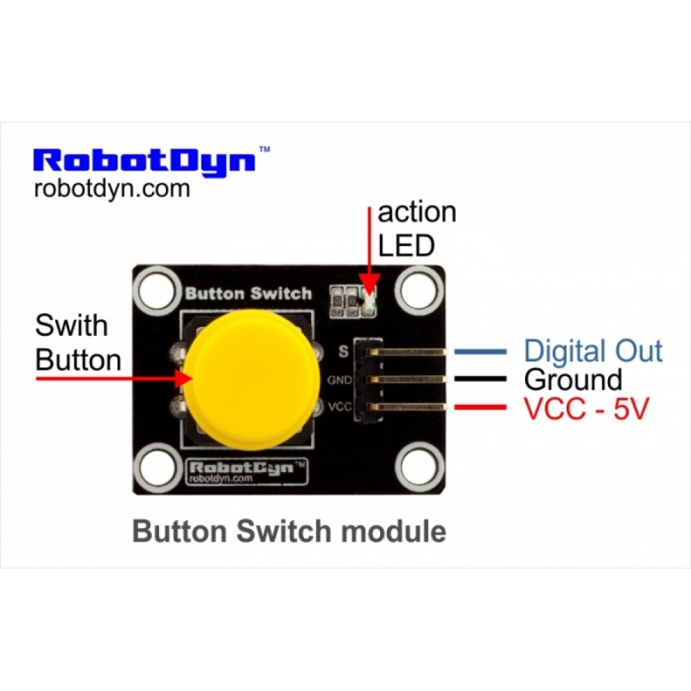
The last thing you need to connect is your button. There are different kind of buttons with different ways to connect. Above you can see the button im using. If you have this, or a similar button with the same pins, you can follow this tutorial. Otherwise you need to google how to connect your button.
There are 3 pins on this button.
GND goes to your ground line on the breadboard
VCC goes to your 5V line on the breadboard
and S is a digital out, goes to digital pin 8.
Yay! Now everything is connected and ready to test.
Testing
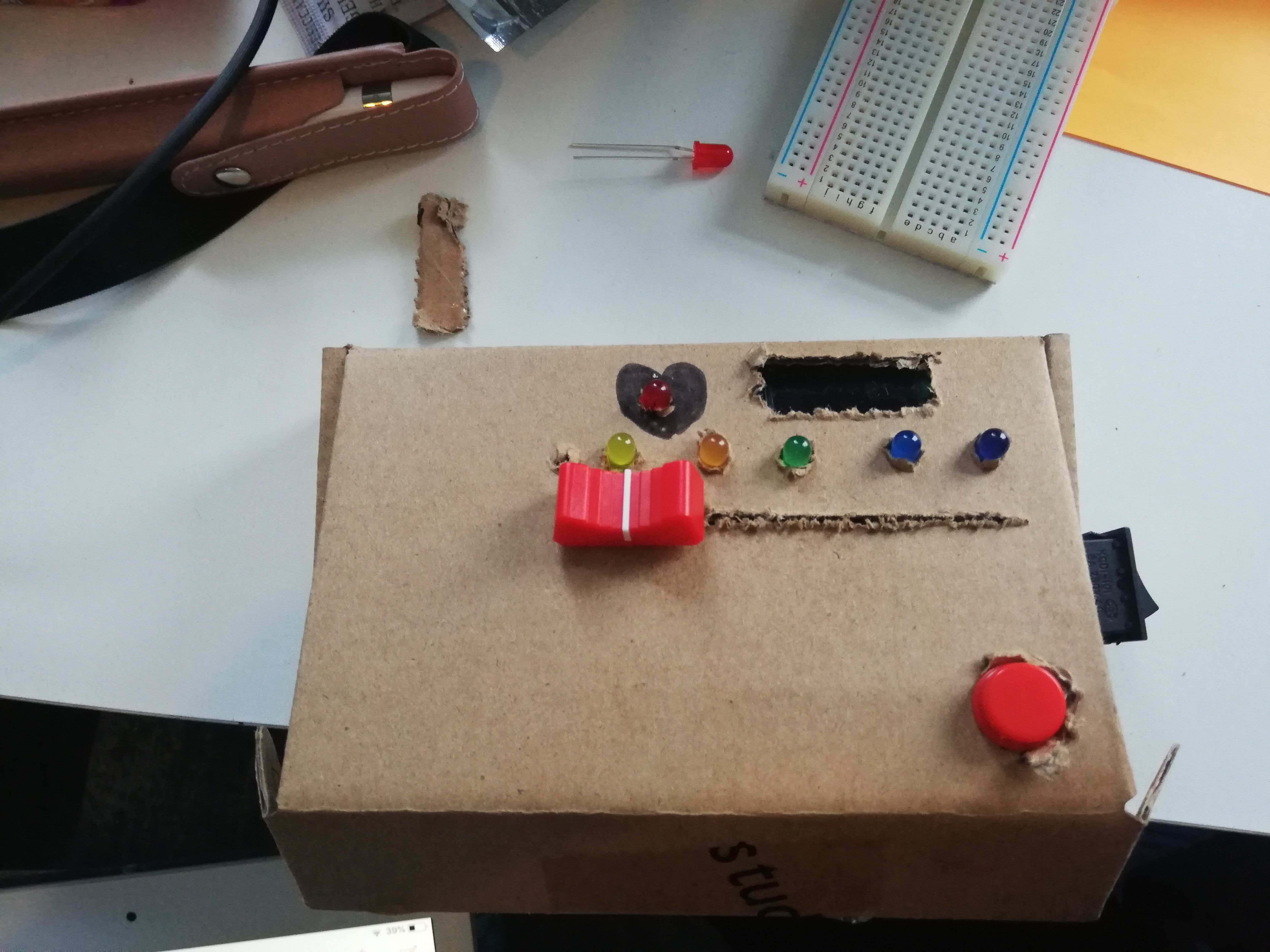
Now, everything is ready to test!
If you havent already, download and upload the code to your Arduino. It might look a bit weird, but your game is now ready to go! You can prototype a case with cardboard (like I did) and decide where you want your slider, button, led screen and led lights.
Solding
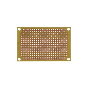
Now, this is the hard part, especially on the Arduino Nano. Before you start solding, make sure you are either outside, or using a mask to prevent yourself from breathing toxic air from the solding iron.
All the things you just connected on your breadboard and arduino, you are going to permanently attach. Make sure all your wires work and you have the right wire in the right place.
Okay, so, this is how I did it.
The 5V line and Ground line need to be recreated with something that you can sold onto. I used a protoboard (image above). Cut the protoboard so you have two smaller parts. It doesn't have to be really big, but make sure they have enough space for your cables. Now, get out that solding iron and sold one wire to the 5V line on your breadboard. The other side should be solded on one of the protoboards. We have recreated a 5V line now, on all of this protoboard. Everything that needs 5V, can be solded to this. Do the same for the other protoboard, but use the ground pin on your Arduino.
Okay so, everything that needed 5V and Ground before, needs to be solded on these boards. You can clutter them all together to make it a bit easier. This means that all your leds should be cabled and the smaller parts should be solded to the ground protoboard. (The other sides should be solded to their digital pins that we prototyped them on before)
Basically, everything you wired, will be solded like this.
When thats done, your project is permanent!
Casing
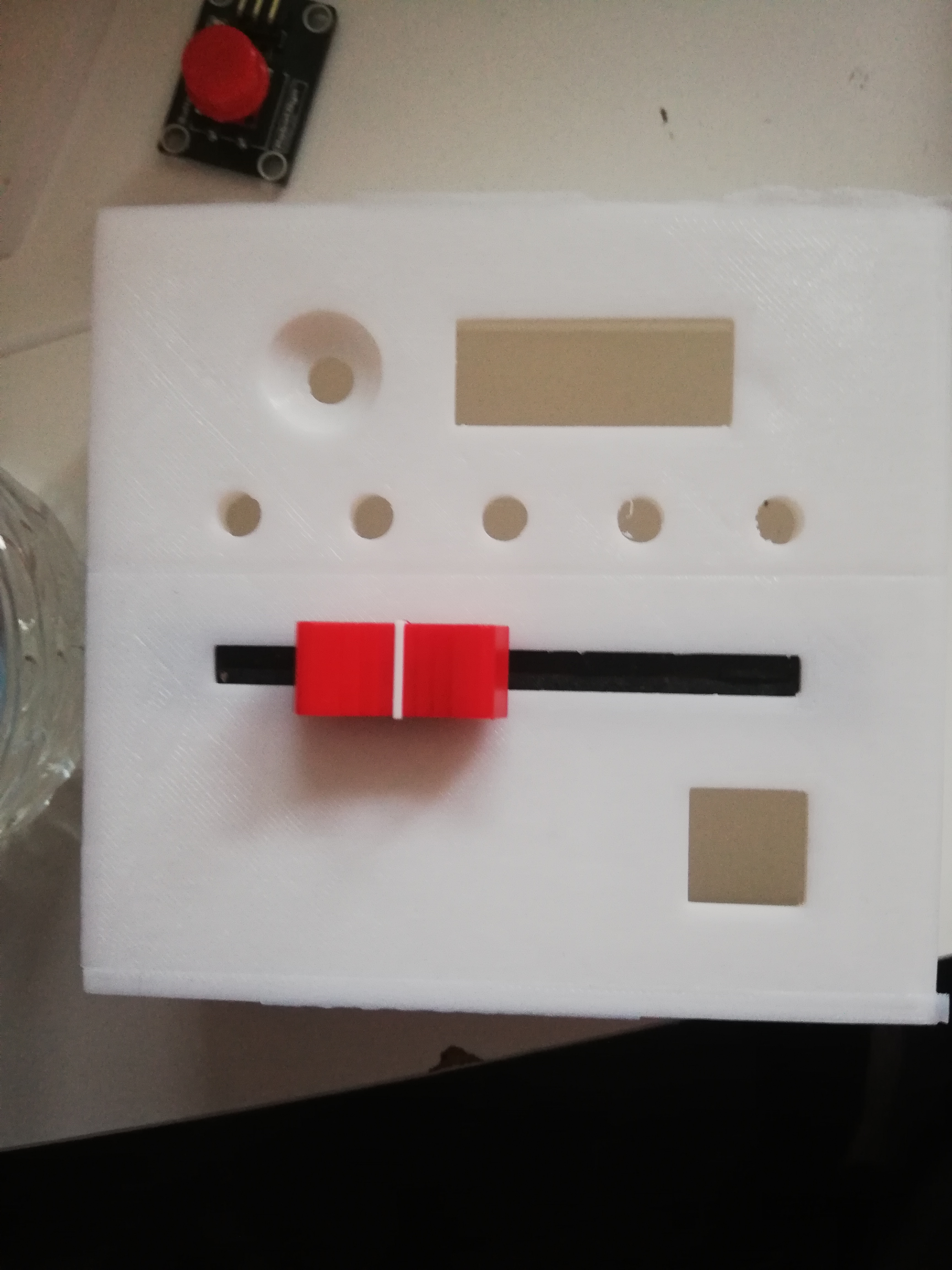
The last step, is putting it all together: you are going to design a case!
This case can be anything you want, as long as the parts fit. My case is a 3D printed model that I designed and someone else 3D modelled for me, I want to upload it, but it has a few flaws in the design, so it's best if you make one yourself. Plus, it will feel like your own project when you do!
So, if you prototyped before, you can use that to make sure you have enough space for all the parts. Also, dont forget to make space for the cable of your arduino to your power source! I hope you will go crazy and use your own materials and colors!
Final Word
So, I hope you enjoyed my instructable and made your own beautifull project. Feel free to change things up as you like. As for me, this project is not over yet. My final design worked, but after a few hours my Arduino stopped working, so I'm hoping to find a solution so it works permanently. I did enjoy this project, even though it was a lot of stress, hours and tears. I hope to make more in the future and that you'll love your project!