Arduino Powered Phase Array
Project Intro:
Most Arduino phase arrays use 5-7 Speakers, with the ability to change both phase and frequency manually, Our goal was to design an array with these limitations simple enough for a grade 11/12 physics class. This project is the creation of an Arduino powered phased array.
What is a phased array?
A phased array is an electronically scanned array where the waves transmitted can be directed to a certain point by changing the delay between the speakers producing noise. In short, a phased array is a sound gun, used to point sound in different directions. To measure the waves and to view how the volts produced by the Arduino change we used an oscilloscope. Oscilloscopes show us the measured signal of the voltage using a graph. The voltage is represented on the vertical axis and time on the horizontal axis. This display will allow you to determine if the behavior of your circuits is working correctly and to find any problems within the circuit. This is a guide on how to make one using an Arduino and some code!
Supplies

- Arduino Uno (x1)
- Breadboard (x1)
- Jumper wires, Colors may vary (a lot)
- 8 ohm Speaker of your choice that connects to the Arduino (x2-5)
- 100 ohm resistors (x2-5)
- A piece of wood or some other long straight thing (to mount the speakers on)
- Hot glue/other adhesive
The Math
How does it work?
Each speaker produces a wave of the same measurements, with each firing one after another on a small delay, producing an overlap of the waves centered on a specific point. This overlap is called constructive interference. When two waves of identical frequencies overlap, the sound is enhanced in that area. By changing the delay between the speakers, you can alter the angle that the constructive interference occurs, allowing you to direct the sound in whatever direction you please.
The Math:
In order to find this distance we used this equation.

Lamda, (λ) is the shared wavelength that the speakers produce, this has to be consistent between the speakers, or the overlap will not occur at regular intervals, it is measured in 1/seconds. Phi, (Φ) Is the phase Total phase shift, or time delay between the speakers pulsing, it is measured in degrees for phase shift or seconds. Distance (d) is measured in meters, and refers to the distance between the speakers. And finally, Theta (θ) the angle shift of the constructive interference. This is some basic imagery of the calculations.

Wiring

The components to wire this project are:
- Arduino uno (x1)
- 8 ohm Speaker (x4-6)
- Jumper wires, colors may vary (x a lot)
- Breadboard (x1)
- 100 ohm resistors (x2-5)
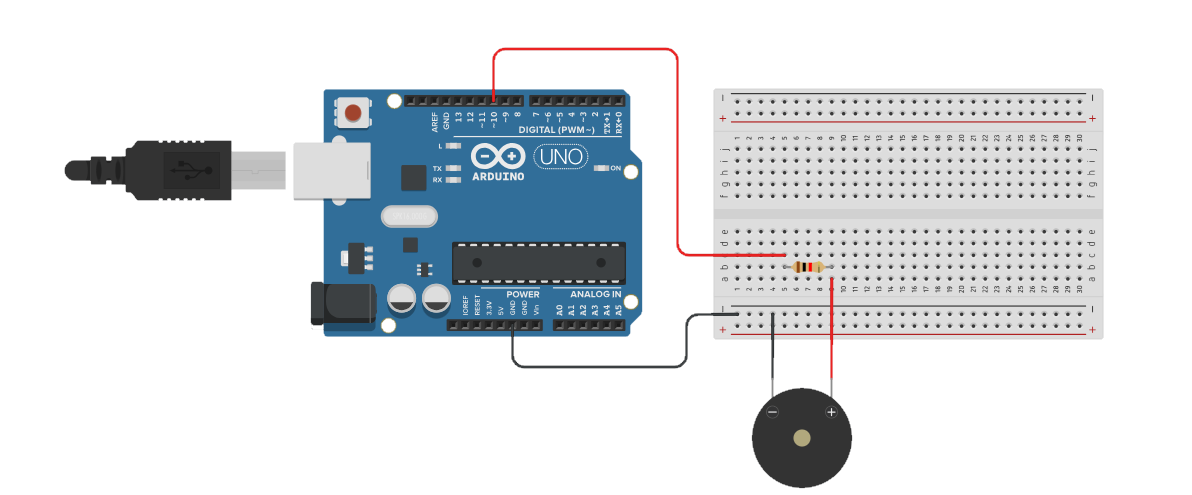
The circuit used to make this project is shown above. The diagram is made using Tinkercad. (See below for details on how to wire specific components)For more information on wiring an Arduino please visit: https://www.instructables.com/Basics-of-Arduino-TINKERCAD/
8 ohm Speaker:
To wire the speakers, connect the red cable to a resistor via breadboard. The other end of the resistor connects to the digital output pins. For this project we wired four speakers to ports 2,3,4,and 5. Connect the black cable to ground on your Arduino or breadboard.
Coding
Once the wiring is complete, you should then move into the code aspect of the project. The premise of the code is to make a phased array with your speakers. Connecting the speakers into the Arduino will make the program run into the speakers, sounding a certain frequency that interchanges between set: HIGH and set: LOW with an angle of your choice we used 30°. During this time, delays are set in-between, forming a phased array. Here is the code we made for our array:
The speaker code


int speakerpin = 2;
int speakerpin2 = 3;
int speakerpin3 = 4;
int speakerpin4 = 5;
int speakerpin5 = 6;
int speakerpin6 = 7;
//2-7 speaker pins are speakers that are connected to your arduino pins.


float frequency = 11258; //float is for storing big numbers.
//11258 is roughly 845 Hz


float period = 1 / frequency * 1000000;
//microseconds, this is how fast it repeats


float Phaseangle = 44.29;
// depending on the angle you chose, the most sound waves will reach that position.


float PhaseDelay = period * Phaseangle / 360 * ((10)^6);
//microseconds as well assumedly, this is delay


unsigned long time;
//time value


unsigned int wavetoggle = 0;
//placeholder int (int: A Variable Data-type that stores numerals. Depending on the function you use the variable will carter to said function and work as a storage unit for data.) for the flip HIGH/LOW of speakers


void setup() {
 Serial.begin(9600);
//serial.begin makes the arduino run at (X) Hz(?) per second
//declare all the speakers as OUTPUT:
 pinMode(speakerpin, OUTPUT);
 pinMode(speakerpin2, OUTPUT);
 pinMode(speakerpin3, OUTPUT);
 pinMode(speakerpin4, OUTPUT);
 pinMode(speakerpin5, OUTPUT);
 pinMode(speakerpin6, OUTPUT);
}


void loop() {
  time = micros();
 //time setting to microseconds, you do this to do a constant ringing


  wavetoggle = ~wavetoggle;
 //essentially: {When Run}: Flips the int of wavetoggle from HIGH to LOW or vice versa
  digitalWrite(speakerpin, wavetoggle);
//turns the speaker HIGH/LOW according to wavetoggle
  while(micros() < time + PhaseDelay*1){}


  digitalWrite(speakerpin2, wavetoggle);
  while(micros() < time + PhaseDelay*2){}
 // *2 delays it after speaker 1


  digitalWrite(speakerpin3, wavetoggle);
  while(micros() < time + PhaseDelay*3){}
// *3 delays it after speaker 2


  digitalWrite(speakerpin4, wavetoggle);
  while(micros() < time + PhaseDelay*4){}
// *4 delays it after speaker 3


  digitalWrite(speakerpin5, wavetoggle);
  while(micros() < time + PhaseDelay*5){}
// *5 delays it after speaker 4


  digitalWrite(speakerpin6, wavetoggle);
  while(micros() < time + PhaseDelay*6){}
// *6 delays it after speaker 5


  while(micros() < time + period){}
//this is what delays at the end
}
Mounting the Speakers
For the code to properly direct waves of sound in a chosen direction, all of the speakers will need to be all facing the same direction spaced equal increments apart.
Materials Needed For This Section
- Wooden board at least 35 cm long (x1)
- Hot glue
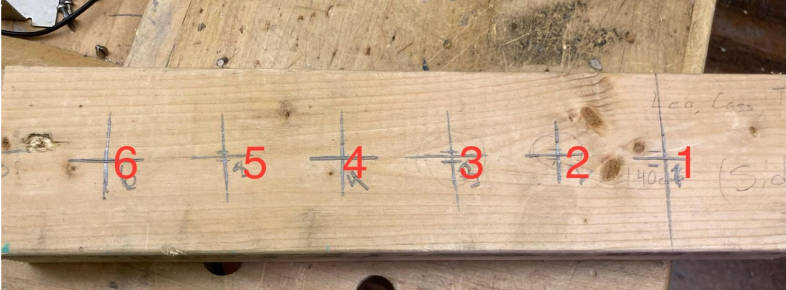
Step One: Mark Out Where You Put Your Speakers
If you are using the code provided with the Instructable, your speakers must be 5 cm apart, measured from the middle of the speakers. Starting from the edge of your board, measure 5 cm in and mark. Go along the rest of the board and keep marking every 5 cm. If you have a 35 cm board, you should have 6 marks to put speakers on, along with 5 cm of space to the edge of the board on either end.
If you are making your own modifications, such as using a 7th speaker or changing the code, the piece of wood may need to be longer to fit your needs. If you’re just adding a 7th speaker, a 40 cm piece of wood should suffice.
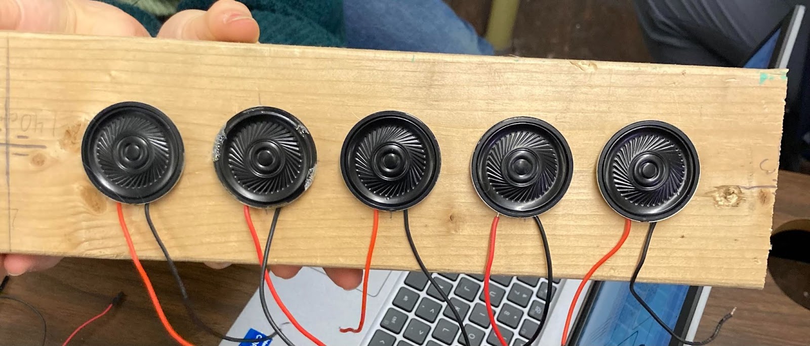
Step Two: Hot Glue Your Speakers On
This step is pretty simple. Put a small dot of hot glue on the line, and then put your speaker on. Press down lightly and apply pressure evenly on your speakers to make sure they lie straight on the wood. Don’t worry if it seems like your speakers are very close together; if you measure from the middle of the speaker to the middle of the next speaker over, it should still be 5 cm.
Testing
We had to test our array under some unique circumstances. To test our array, we placed it in a soundproof room. A system of microphones was built to check the wave angle of our sonar array. We placed MAX4466 electrek microphones every 30°, 40 cm from the center. To test both our array and the microphones, we placed the array into the room with a set angle written into the code, hoping we get data back that our goal has been achieved.