Arduino-Powered Night Light

Ever wished for an arduino powered lamp that would operate without a switch?
I made this lamp as a SIDE project for my Principles of Engineering class led by Ms.Berbawy!
First off. I'd like to make a shoutout to TeachEngineering for providing reference for the circuit! This project was inspired by my nightlight at home that constantly kept dying on me.
Throughout my process of designing, I learned skills like programming, 3D modelling in Fusion, and 3D printing .
Supplies
Materials :
- 1 Arduino Uno Rev3
- 1 Breadboard
- ~12 Male-male Jumper Wires
- Prusa PLA Filament
- 1 Photoresistor
- 1 10k ohm resistor
- 4 330 ohm resistor
- 4 circuit LED bulbs
- 1 set of epoxy resin
- Optional : Air Dry Clay
Software :
- Arduino IDE
- Fusion 360
- TinkerCAD
- PrusaSlicer
Equipment:
- Prusa Mini+ 3D printer
Making the Circuit on TinkerCAD

Before actually building a physical circuit, we must make a circuit on TinkerCAD for two reasons
- So that we don't cause any accidents when creating the physical circuit
- So that our circuit is organized in an efficient manner
If you are not familiar with TinkerCAD, it's software used to help create circuits and 3D models, and it's free.To make the first circuit, create a TinkerCAD account and open a new workspace under Circuits tab. When you open your workspace, you have access to all materials on the right of your page. Gather all materials for your circuit onto your workspace as shown above.
We will construct two circuits, one for resistor and one for the LEDs:
- Resistor Circuit
- Arduino Uno- 1
- Small Breadboard - 1
- Photoresistor - 1
- 10k ohm resistor - 1
- LED circuit
- Arduino - 1
- Breadboard - 1
- Photoresistor - 1
- LEDs - 4
- 10k ohm resistors - 1
- 330 ohm resistors - 4
Test TinkerCAD Circuit With Photoresistor!


It's necessary to test the highest value of the photoresistor, because it will help us figure out when the night light will power on and power off , on its own. The highest value on the TinkerCAD circuit is different than the physical circuit because TinkerCAD uses a simulated environment while the physical circuit depends on the amount of light in your current location. When I was programming my physical model, I tried using the same program from TinkerCAD in Arduino IDE, I noticed the LEDs did not blink at all during the first test run.
- Connect the photoresistor and the 10k ohm resistor to the breadboard.
- row f ; column 10 , place the photoresistor
- row h ; column 11 , place the resistor
- Connect the red wire from point on row i ; column 11 to the A0 pin
- Connect the green wire from point on row i ; column 15 to 5V pin
- Connect the purple wire from point on row i; column 10 to the GND pin
Now that we placed all the components , we program the Arduino to read and display value from the photoresistor on the Serial Monitor. Go to "Code" on the top right of the page and set the option to "Text", which will allow you to program your code into the Arduino.
- As shown above, our first command is Serial.begin(9600), which sets the program to run at 9600 bits/second, the standard communication speed for the Arduino.
- Set the A0 pin to read photoresistor value as an integer
int SensorValue = analogRead(A0);
Serial.println(SensorValue);
- SensorValue = value from the photo resistor
- analogRead() = reads the value from the specific pin (values between 0 - 1023)
- Serial.println() = prints out the value on to the Serial Monitor when running the program
- Lastly, set the time as to how long the program should pause before continuing using the delay() function.
- delay() = uses a value to communicate amount of time to pause
- 1000 = 1 second
- The higher the value, the more time it pauses
- The lower the value, the less time it pauses
Now , open the Serial Monitor of the bottom of the Code page , and run it.
- When there is little / no light detected by the photoresistor, intensity value decreases
- When there is light detected, intensity value increases
Test TinkerCAD Circuit With LED


For the LEDs circuit , I did it in 2 parts :
- 1 LED
- 4 LEDs
For one LED, we use with one 330 ohm resistor , connected to pin 13 of the Arduino board. When programming pin 13 will be set as the output because it will respond to the light intensity value. If there is a high value read by the photoresistor, the LEDs would stop blinking because it means that light is detected in the surrounding . If there is a low value, the LEDs would blink because no light is detected in that case.
Steps:
- Leave the photoresistor and the 10k ohm resistor on the bread board
- connect the blue wire from the point on row g ; column 11 to the A0 pin on one leg of the photoresistor
- connect the brown wire from the (+) rail to the GND pin
- Connect the red wire to connect from the point on row j ; column 15 to the 5V pin
- Connect the white wire to the photoresistor from (+) rail ; column 6 to row g ; column 10
- sends current to the other leg of the photoresistor
From this point, connect the LED and the 330 ohm resistor onto the circuit as well. Connect the LED starting from row a ; column 25 on the cathode and connect the resistor starting from row c ; column 26. Once we place all the components onto the breadboard, connect the green wire to pin 13.
We are testing only one LED, and so we should connect to pin 13 and set it as an output. For every output, there should be an input, so the A0 pin will be set as the input because it is connected to one leg of the photoresistor. Therefore, the A0 pin will read light intensity value, which will determine when the LEDs powers on and off.
- use the pinMode() function to set the pins as inputs and outputs
- set up the standard communication as 9600 bits/second
pinMode(13, OUTPUT);
pinMode(A0, INPUT);
Serial.begin(9600);
Test TinkerCAD Circuit With Multiple LEDs


For the other 3 LEDs, we will use 3 more 330 ohm resistors and set up just like the first LED. This time, each of the 3 other resistors will be connected to pins 10, 11, and 12 and set as outputs. Repeat the same steps from first LED for the other 3 LEDs.
- Place each of these components on these points
- LED 2 = row a ; column 19
- resistor 2 = row c ; column 20
- Yellow Wire : connect from row b ; column 19 to (+) rail ; column 19
- LED 3 = row a ; column 13
- resistor 3 = row c ; column 14
- Black Wire : connect from row b ; column 13 to (+) rail ; column 13
- LED 4 = row a ; column 7
- resistor 4 = row c ; column 8
- Purple Wire : connect from row b ; column 7 to (+) rail ; column 7
- Connect the green wire from row d ; column 12 to pin 10
- Connect the grey wire from row d ; column 18 to pin 11
- Connect the orange wire from row d ; column 24 to pin 12
Programming the 3 LEDs
- repeat same steps for the 1st LED on to the other 3 LEDs
- set the other pins as outputs but A0 pin is the same input
- set up the standard communication speed of 9600 bits/second
pinMode(10, OUTPUT);
pinMode(11, OUTPUT);
pinMode(12, OUTPUT);
pinMode(13, OUTPUT);
pinMode(A0, INPUT);
Serial.begin(9600);
- repeat the same procedures, use the digitalWrite(pin, value) LED bulbs
- set the amount of time the program must wait before continuing with delay() functions between each pin
digitalWrite (13, HIGH);
delay(500);
digitalWrite (13, LOW);
delay(500);
digitalWrite (12, HIGH);
delay(500);
digitalWrite (12, LOW);
delay(500);
digitalWrite (11, HIGH);
delay(500);
digitalWrite (11, LOW);
delay(500);
digitalWrite (10, LOW);
delay(500);
digitalWrite (10, LOW);
delay(500);
- Run the program, see what happens to all the bulbs when you test the circuit LEDs. They should light up in a pattern.
Building Physical Circuit


Now, it's time to assemble our physical circuit! Using our Circuit Model from TinkerCAD, we have to build the physical model of the circuit to test in real-time! When connecting the LEDS, there are 2 legs of the bulb which Anode and Cathode. The way to tell them apart is that the anode is longer than the cathode in the physical bulb. So, do not mix them up.
Programming the physical circuit :
- Plug in one end of the cord into the USB connector and the other end into the computer.
- Download Arduino IDE and open up a page to start your code.
- Enter in your program from TinkerCAD into Arduino IDE for the 4 LEDs, verify to ensure it's error-free before uploading. If no errors are detected, upload, and test the circuit by switching your room lights on and off.
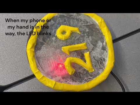
- When the lights are out, you should see it in blink in a pattern from the last LED to the first LED.
What happens if it does not upload?
Do make sure you enter the correct port. At first, I noticed only one bulb blinked when plugged in and found out that it just means the Arduino is not fully set up. In order to set up the Arduino, click on "Tools" , then when you click on "Ports", choose the Port that says "(Arduino Uno)".
Designing the Base


Now, that we moved past working with circuits, we must create a base to cover the circuit! For this step, we have to access Autodesk Fusion360, which means we need to create an Autodesk account. This account gives you access to all design software developed by Autodesk. Once you sign in, you download Fusion360 and sign in to start creating the first design. For this part, I had no experience with Fusion 360, so I learned the basics through the 100 Days of Fusion website.
Since I was starting in 3D design and modeling, I went with a basic design. When you open Fusion, create a new design for the base. We are going to create 2 compartments to secure the circuit in place.
- Measure the sides and take the dimensions of both Breadboard and Arduino
- Measure the height between the wires as it will help when building the wall between compartments
- Breadboard : 3.6 x 2.3 in
- Arduino : 3.5 in x 2.25 in
- Wall/Sides : 0.1 in thick , 0.9 in height
Creating the Base
- Create a sketch in Fusion to make the 2 compartments and make sure to increase the dimensions of both compartments. During my first design, I created the compartments using the dimensions I measured on the circuit and when I 3D printed that model, the circuit did not fit in their respective compartments . So, I changed the dimensions of both compartments with the below dimensions.
- Breadboard : 3.8 in x 2.5 in
- Arduino : 3.8 in x 2.4 in
- Create a sketch of 3 rectangles on the xy-plane. On the plane, I created the 1st rectangle for the Breadboard and under it, I created a second rectangle to represent the wall that separates the Arduino and Breadboard , with dimensions of 3.8 in x 0.1 in, adjacent to the first rectangle. Under the "wall" , create the third rectangle for the Arduino adjacent to the "wall".
- Extrude the wall 0.9 inches high and the rectangular bases by 0.1 inch thick. Along the other 3 sides of the bases, create the same 0.1 inch thick walls and extrude them 0.8 inches high. Make sure that during each extrusion, you are joining the bodies to make one design. This makes it easier to 3D print in 1 piece for the test prints and the final print.
We have finished creating the compartments, we will start on the exterior of the base. I wanted to focus on the bottom face of the exterior, so I rotated the design to the bottom view first.
- Find your center of the circle by creating 2 lines on the box across the vertices. The first line connects from the top right vertex to the bottom left, while the second line connects from the top left vertex to the bottom right.The point where they intersect is your center.
- From the center, create a 6.7 in wide circle and extrude upward by 0.1 and on the same circle, rotate the base to the top face and create a 6.5 in wide circle on top. Between the circumferences of the two circles, there is 0.2 in space. Click in the space and extrude the wall to 1.5 in height. Join all the bodies together during each extrusion.
Almost everything is ready, except the holes where the USB connector will enter when plugging the Arduino to the computer . Going back to the compartments, click on the Arduino compartment and create a sketch of a 1.15 in x 0.8 in rectangular hole on the shorter face and extrude out by 0.2 in , cutting through wall of the compartment but not the exterior.
- Arduino : 3.6 in x 2.3 in
- Face dimensions: 2.3 in x 1.5 in
- On the same face , create a smaller rectangle with 0.6 in x 0.6 in dimensions and extrude and cut all the way past the cylinder exterior for the hole.
We have everything ready except the screw holes to secure the Arduino, so we must create screw holes for the the design.
- Click on the circle face from earlier and create a sketch. Measure the distance from the screw holes from each side of the Arduino compartment and between other screw holes, With the measurements, sketch lines on the plane to mark the points for the screw holes and finish the sketch.
- From those points, click on "Hole" and adjust the measurements on the "Hole" panel
- Hole Diameter : 3.2 mm
- Hole Height : 2.54 mm
- Do thread the holes for the screws
The product is finished!
3D Printing Base


Before we officially 3D print our whole design, we must 3D print some test models to ensure we get the measurements correct! So, if you have access to a PrusaSlicer Mini+, do download the Prusa Software to help with the 3D printing process. I did this step in parts, with test printing only the Arduino compartment first, then printing the full base. Before I started 3D printing, I imported the design from Fusion into Prusa as a .3mf file.
For the first part, test print just the Arduino compartment to ensure it fits well and screw holes were plotted correctly . When you open your project on Prusa, you can simply use the "trim" option on the left panel to cut off parts of the design for the test prints. For this instance, I use the "trim" option to cut off the rest of the base so that I could just print the Arduino compartment. Once I was done trimming, I clicked on "Slice Now" which shows the print settings and amount of time to print.
- On the right there are settings for the print, such as Infill, Brim, and Supports. For the test prints, set your Prusa to 10% infill with no supports and set temperature to 230 degrees Celsius.
- Once everything is done, click on "Export G-code" and download your file into an SD card for the printer
- Plug in the SD card, and make sure to add a thin layer of Elmer's glue stick on the build plate to prevent the print from sticking permanently during the 3D printing process. For this project, I added Purple Gold color Prusa PLA Filament into the machine for the final model, but you can choose whichever color you like, because for my test prints, I used different PLA filament colors.
- Adjust the print settings on the 3D print machine to ensure all settings are set correctly, and then create the test print.
Final Model
- Repeat the same steps from importing the base into Prusa, but this time, leave the base as it is with no changes.
- If the test prints worked , this serves as your final print.
- For the final model, increase the infill to 15% with no supports.
You have your physical base.
Designing Diffuser


The idea of the design is to have a lid that easily is placed on top of the base. Just like for the base, I opened Fusion and started a new design for the diffuser. For this step, I had to create a total of 3 circles. One on the bottom face and the other 2 on the top face of the design.
- For the diffuser, we are creating a circular shape diffuser, since the base is cylindrical , so I created a sketch on the xy-plane , and on that sketch, I created a 6.6 in circle from the center . Finish the sketch and extrude the circle downwards by 0.1 in. Since this is a diffuser, the material should be transparent so that light can pass through when the nightlight operates. Change the physical material to "Plastic Transparent".
- On the bottom face, create a sketch of a 6.5 in wide circle, then a 6.4 in wide circle on top, finish the sketch and extrude
- After the extrusion, make into a new body and change the physical material
- For my model, I changed the material to "Porcelain".
- Within that 0.1 in space between the circles, extrude down by 1 in
- Rotate the design back to the top view and create a sketch of any design you like . For my model, I typed in my number 219 in the center using the "Text" feature under the "Create" tab.
Physical Model:
- I used epoxy resin to make the diffuser instead. It comes in two parts, A and B
- Part A = resin
- Part B = hardener
- I added both parts in a 1:1 ratio , mix slowly together before adding into the mold
- Be very precise in measuring ! If a measurement is slightly off, it may affect the outcome of your diffuser.
- Once mixed, pour in the plate mold and let it cure overnight next to a heater because it speeds up cure time .
- The next morning, I picked it off the mold and tried cleaning all the residue from the mold.
If you want to make a physical design...
- For my example, I used air dry clay and molded into the numbers "219"
- When it was molded, I placed it on the cured resin and let it set overnight by the heater.
- For my project , I painted with white and covered with duct tape . However, it's completely optional to do it for your own.
Final Models + Conclusion


Now you have your models ready ! Once you added your circuit in to their respective compartments, slowly place your diffuser on top!
- Slowly try to push the circuits inside their compartments .
- Do not try to force them to fit in the compartments as you may risk breaking it in the process.
- Secure the wires to make sure they are connected when testing the circuit in the final product .
Plug in your model through the outlet space and into your computer, run the program, and you have your own night light!
–––––––––––––––––––––––––––––––––––––––––––––––––––––––––––––––––––––––––––––––
It took me around 5 months to assemble the entire project and program the circuits for the project. Along the way, I got experience in 3D modelling and design with Fusion as well as programming a circuit for the first time. There was definitely obstacles along the way when it came to different steps from measuring dimensions to printing perfect models of my base. I really want to say a big thanks to Ms. Berbawy for helping me throughout the course of the project.
While it was a long process , I had quite some fun using ideas and creativity to design this project. While some say it looks really easy to accomplish , I would say the opposite because I had to pay a lot of attention to detail in my design to make the final product come out perfect. I think my efforts really paid off through this project because I am impressed by my outcomes, especially because this was my first time ever doing a next-level challenging project .