Arduino Pong Tennis PCB | Arduino, Autodesk Eagle and JLCPCB
by Chris-H in Circuits > Arduino
2622 Views, 14 Favorites, 0 Comments
Arduino Pong Tennis PCB | Arduino, Autodesk Eagle and JLCPCB
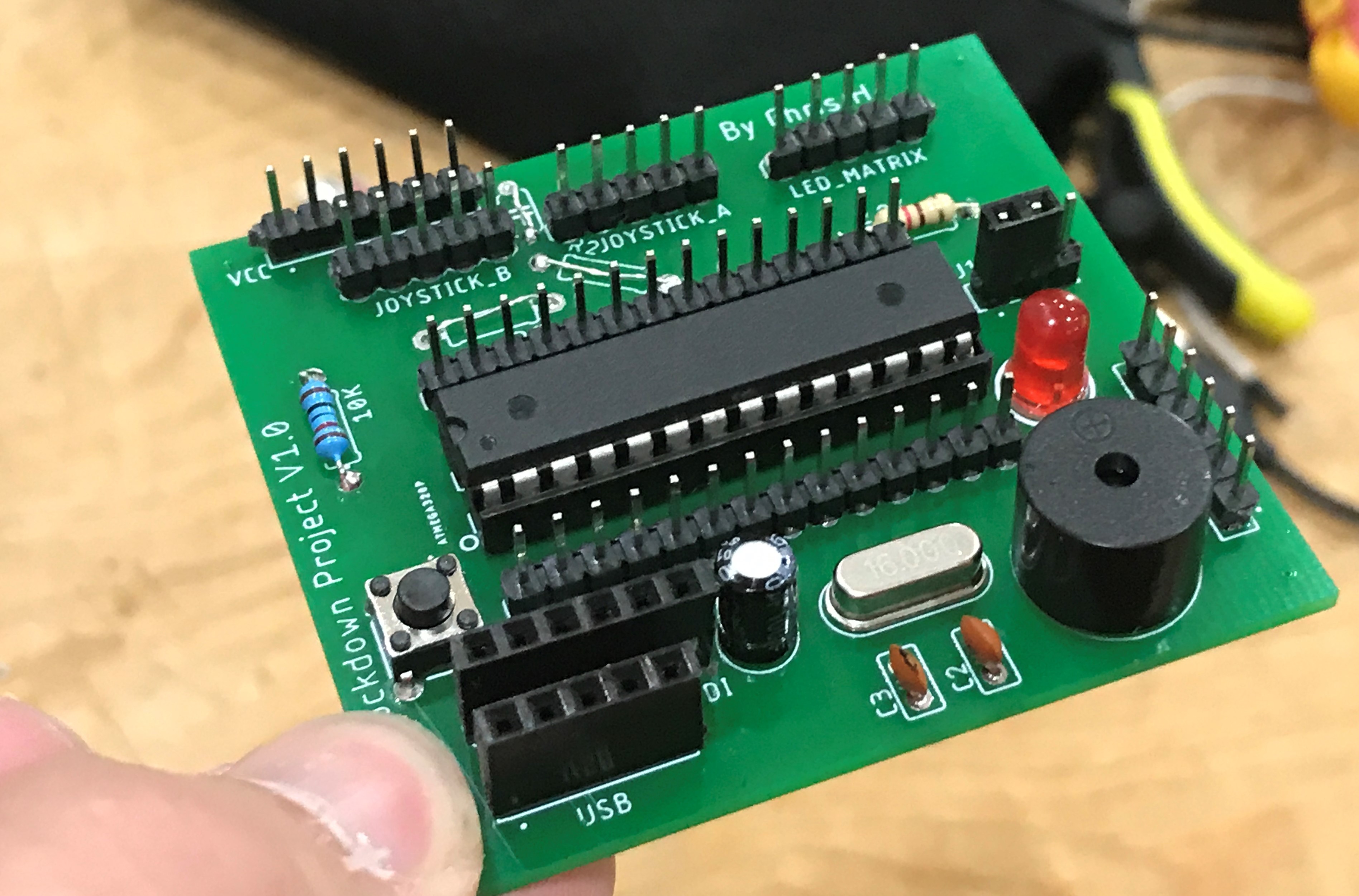
This Instructable follows on from my 'Pong Tennis With LED Matrix, Arduino and Joysticks' project where we completed the wiring for the project and wrote the code. It can be found here. Or by searching Instructables for "Pong Tennis With LED Matrix, Arduino and Joysticks".
The project is intended for everyone from beginners up however this Instructable targets those who want to take the previous pong project to the next level and put it on a custom made PCB.
Creating the Schematic (Using Autodesk Eagle)
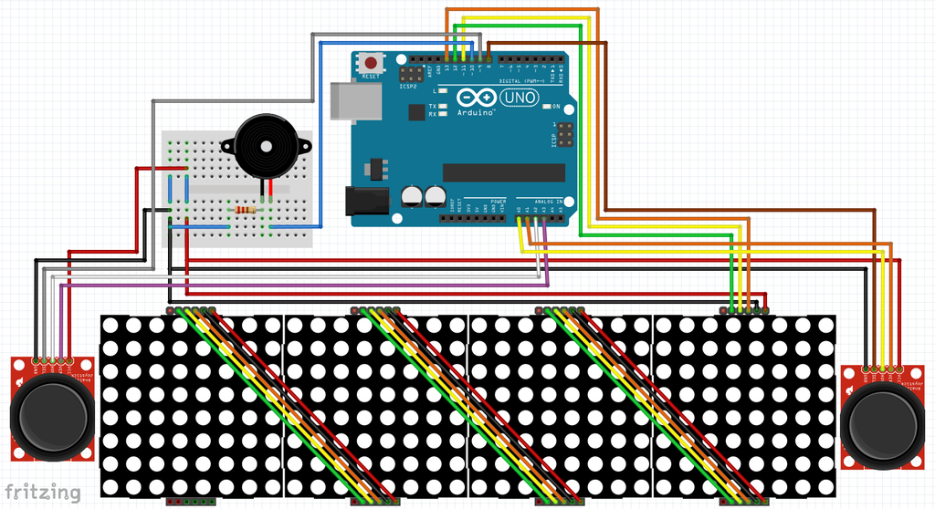
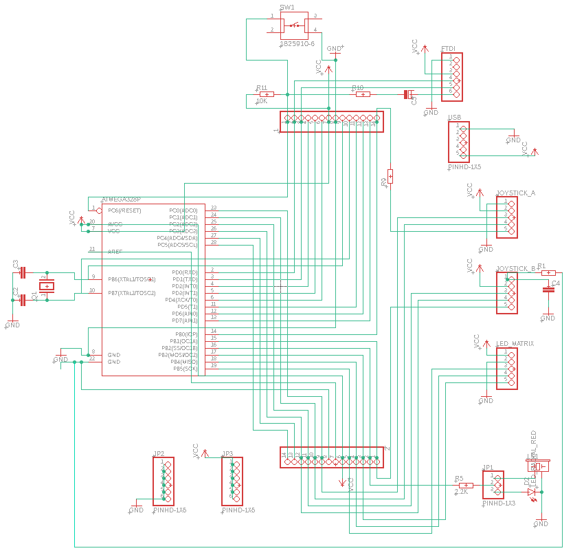
To design the circuit board you first need to draw a schematic of your design on a piece of EDA (Electronic Design Automation) software, I'm using Autodesk Eagle as part of Fusion 360, a popular CAD software. I choose to use Autodesk Eagle as I was already familiar with other Autodesk software and was following the excellent Instructables Class on PCB design which can be found here.
I downloaded it from the Autodesk website here as part of the fusion 360 package.
Drawing a schematic is an easy process which involves finding the components you need in the components library, placing them on the page and then making the correct connections. This process is greatly simplified if you have a schematic to work from before drawing it out on the computer. I will be using the wiring diagram from my previous Instructable shown above.
As you can see in the second image you use the green wires to connect the components placed from the parts menu together. I have also added headers for the Arduino connections, Power and Ground so I have connections for future upgrades. Soldering headers onto these connections is optional.
Convert Schematic to PCB Design
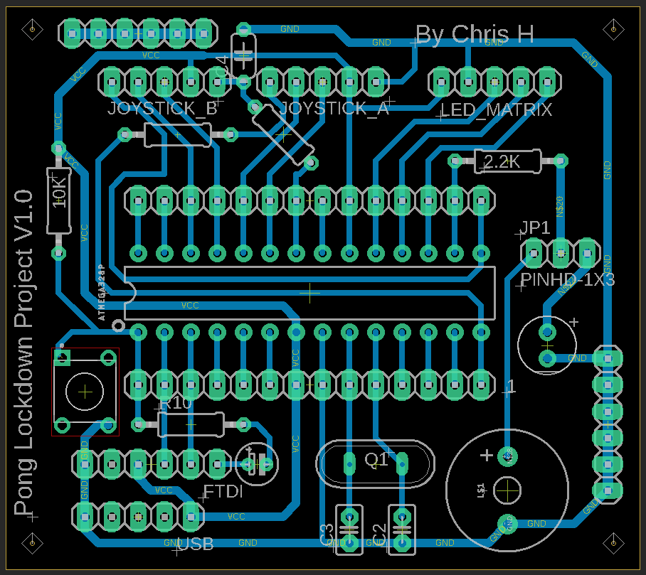
Once you have completed the Schematic you need to convert this into a board design. To do this click on the 'Switch to PCB' button in the top left in Fusion 360 or in eagle click 'SCH BRD' button next to save and print on the top bar. You will be asked whether you want to create a new document click yes.
You will be presented with a board and a jumble of components with lines between them. Try and arrange these components so the lines are as short as possible and, if possible the wires aren't crossing. You can then use the 'Connect' tool to draw on all the wires. If you do need to cross wires you can switch between the top and bottom layer of the board by using the drop down where it says '1 Top' then click '16 Bottom' to draw the PCB traces on the bottom of the board. You can switch back in the same way. To connect traces between layers you can use vias.
Above you can see what the PCB looks like after arranging all the components, I managed to fit all my traces on the bottom layer.
Export PCB Design to Gerber Files
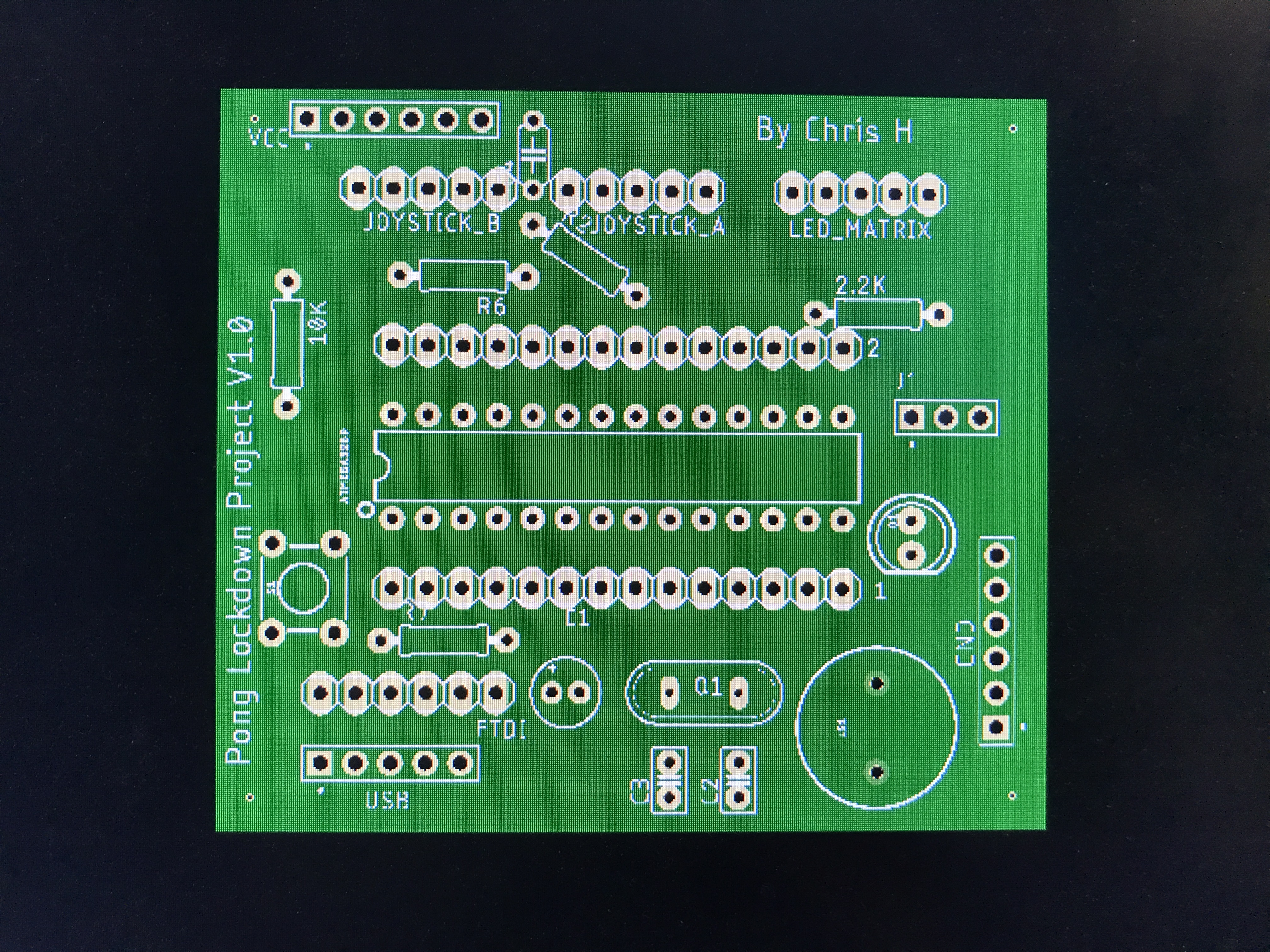
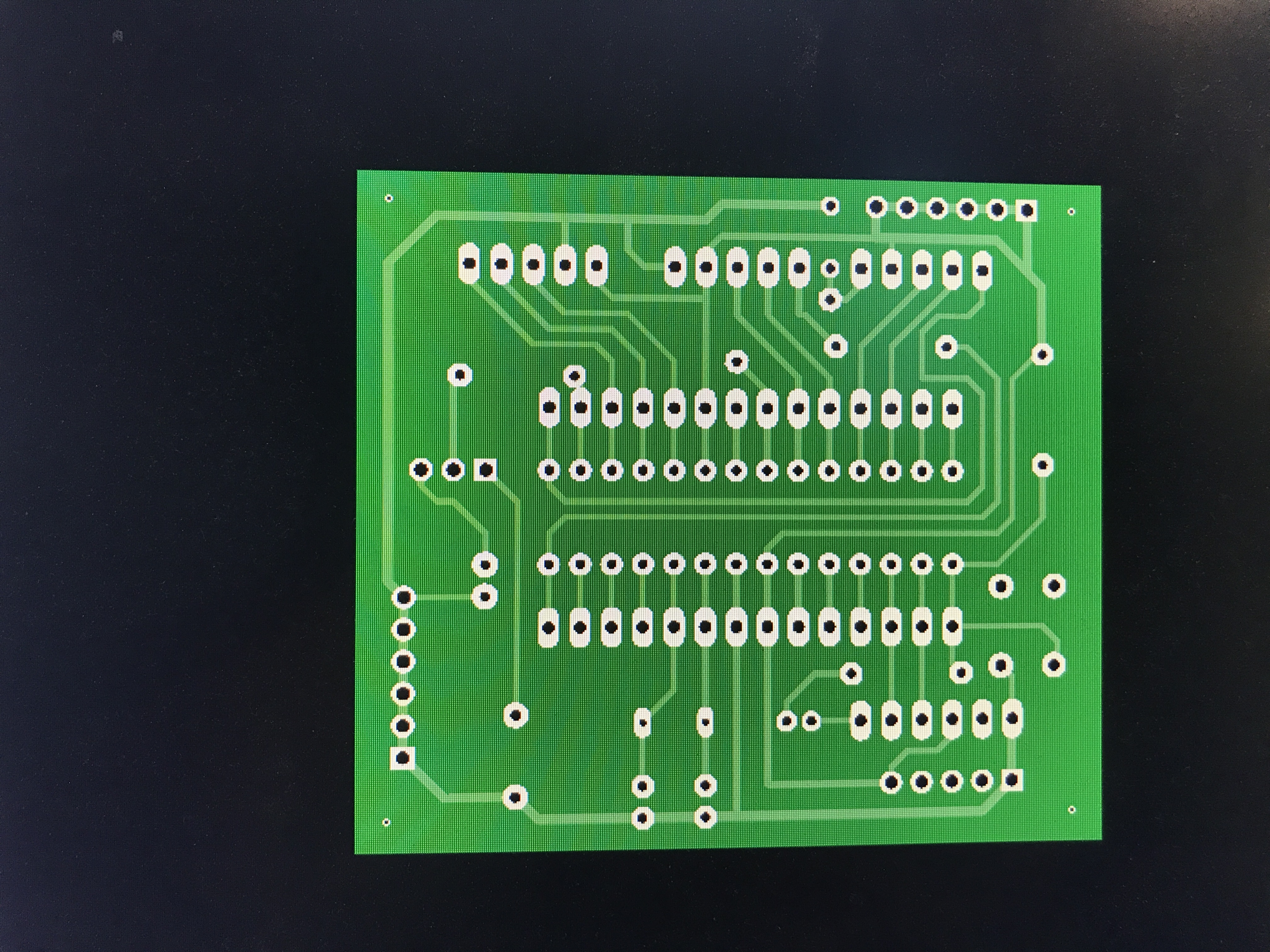
After completing your PCB you need to export it into something a Manufacturing service can understand. In Fusion 360 go to the Manufacturing tab and click 'CAM Export' and in Eagle click 'Generate CAM Data'. This will output a .zip file that you can upload to JLCPCB, PCBway or a similar service.
Order From JLCPCB.
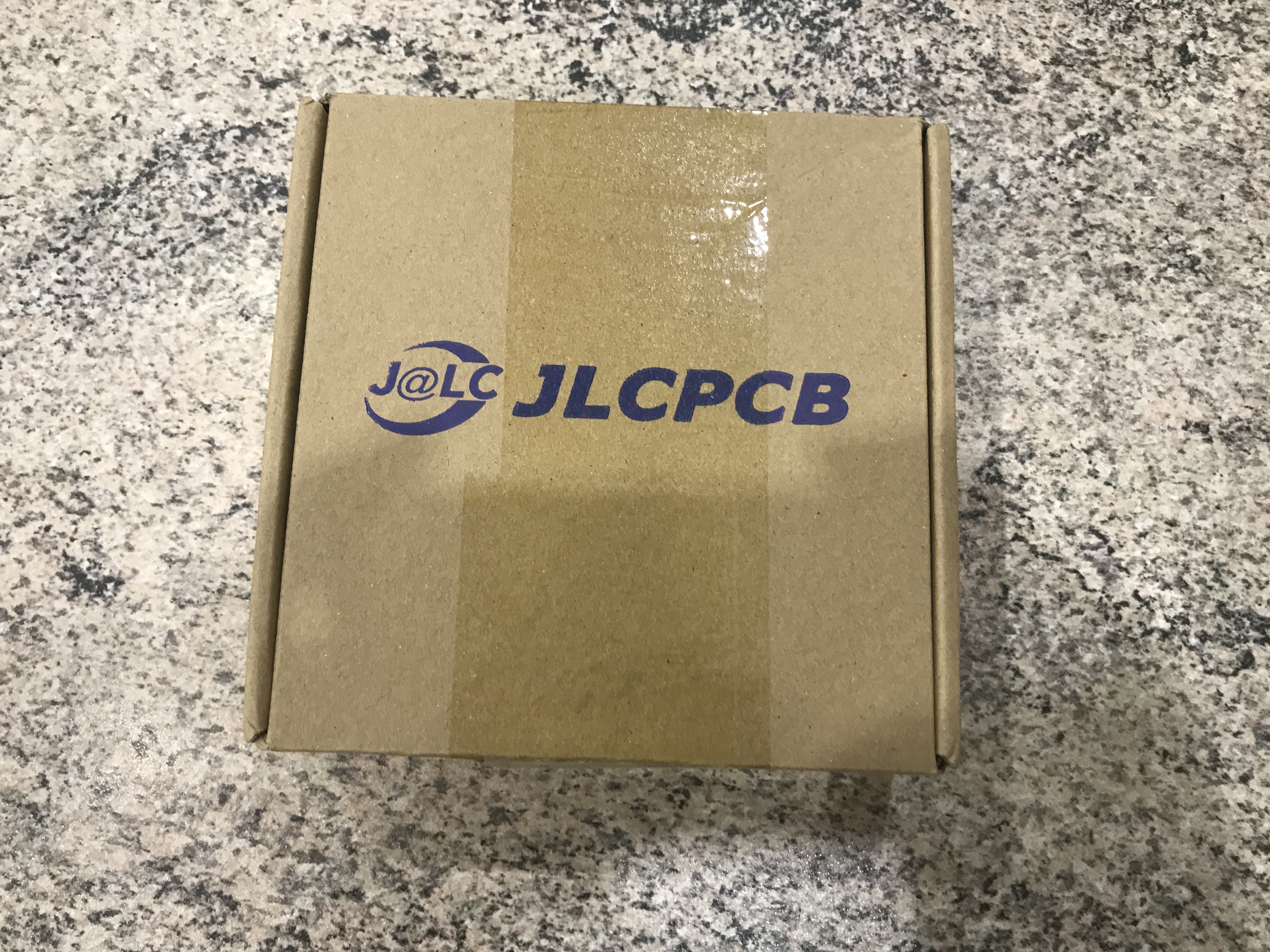
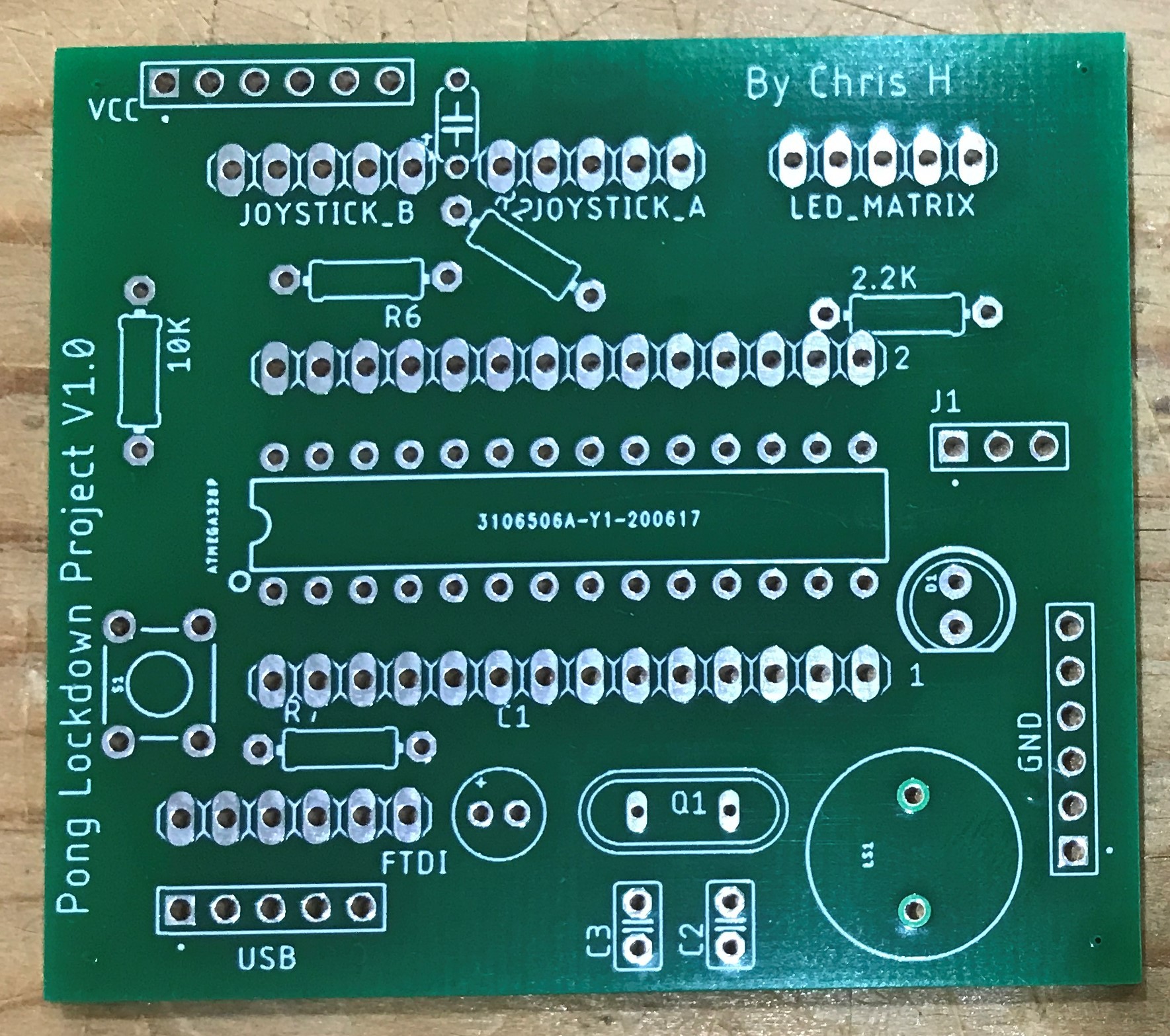
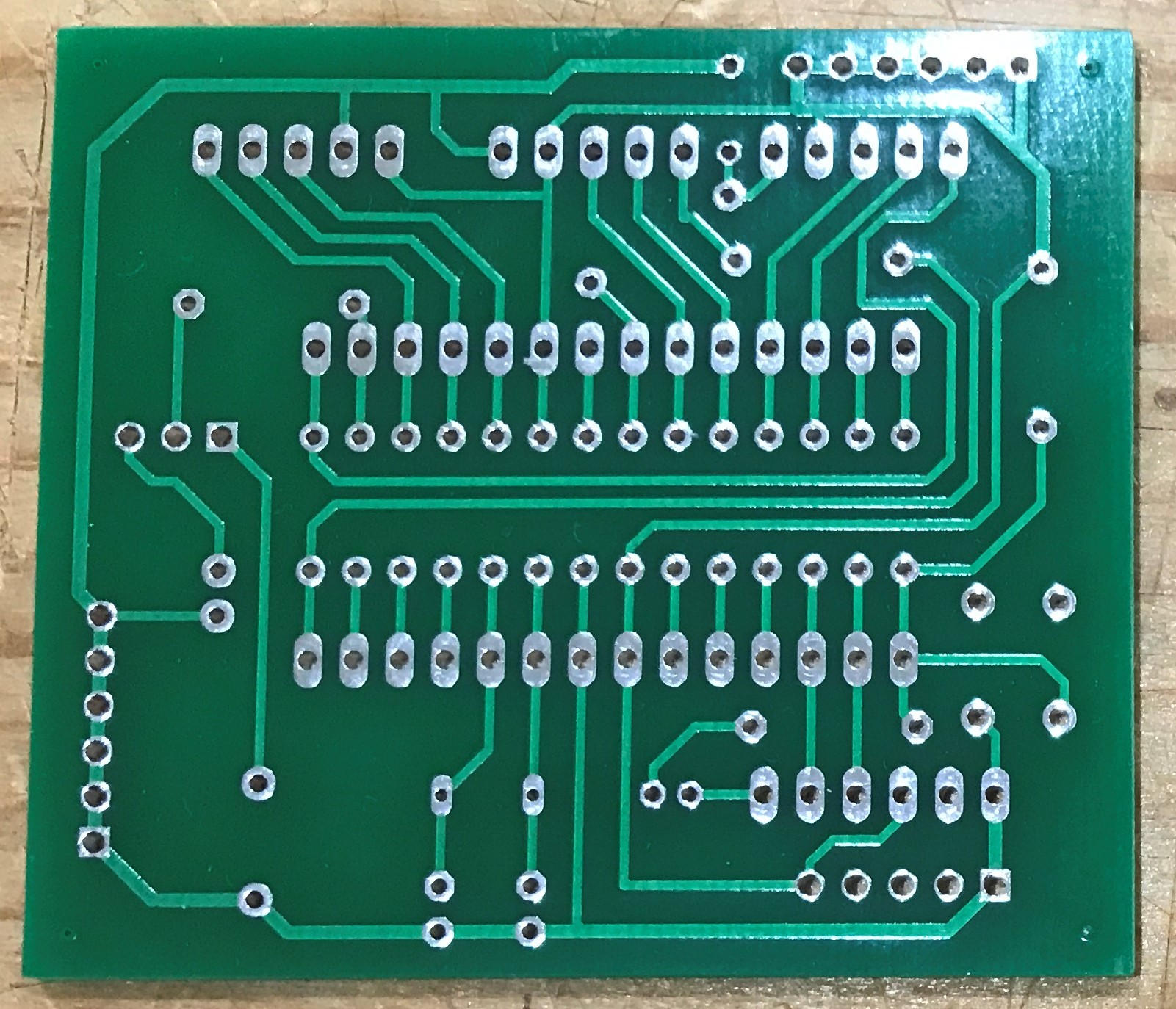
I got 5 of my PCBs manufactured at a very low cost, they took 2-3 weeks to arrive.
Its a really simple process once you have the .zip of files exported from Eagle.
Upload this .zip file to JLCPCB and it will do the rest, you can change the color if you want however I choose to leave it as green because of the faster shipping time.
Collect Components
To Solder the PCB you will need the following components;
- 1x PCB
- 1x 28-pin IC Socket
- 1x Atmega 328P IC
- 1x Buzzer (12mm)
- 1x 5mm LED
- 1x 6mm Pushbutton
- 1x 16Mhz Crystal Oscillator
- 1x 2.2K Resistor
- 1x 10K Resistor
- 1x 100uF Capacitor
- 1x 5-Pin Female Header
- 1x 6-Pin Female Header
- 1x 3-Pin Made Header
- 1x 2.54mm Jumper
- 2x 22pF Capacitor
- 3x 5-Pin Male Header
You will also need the following tools;
- Soldering Iron
- Heat-Proof Mat
- Wire Cutters
- Solder
Solder Resistors, Capacitor and Crystal
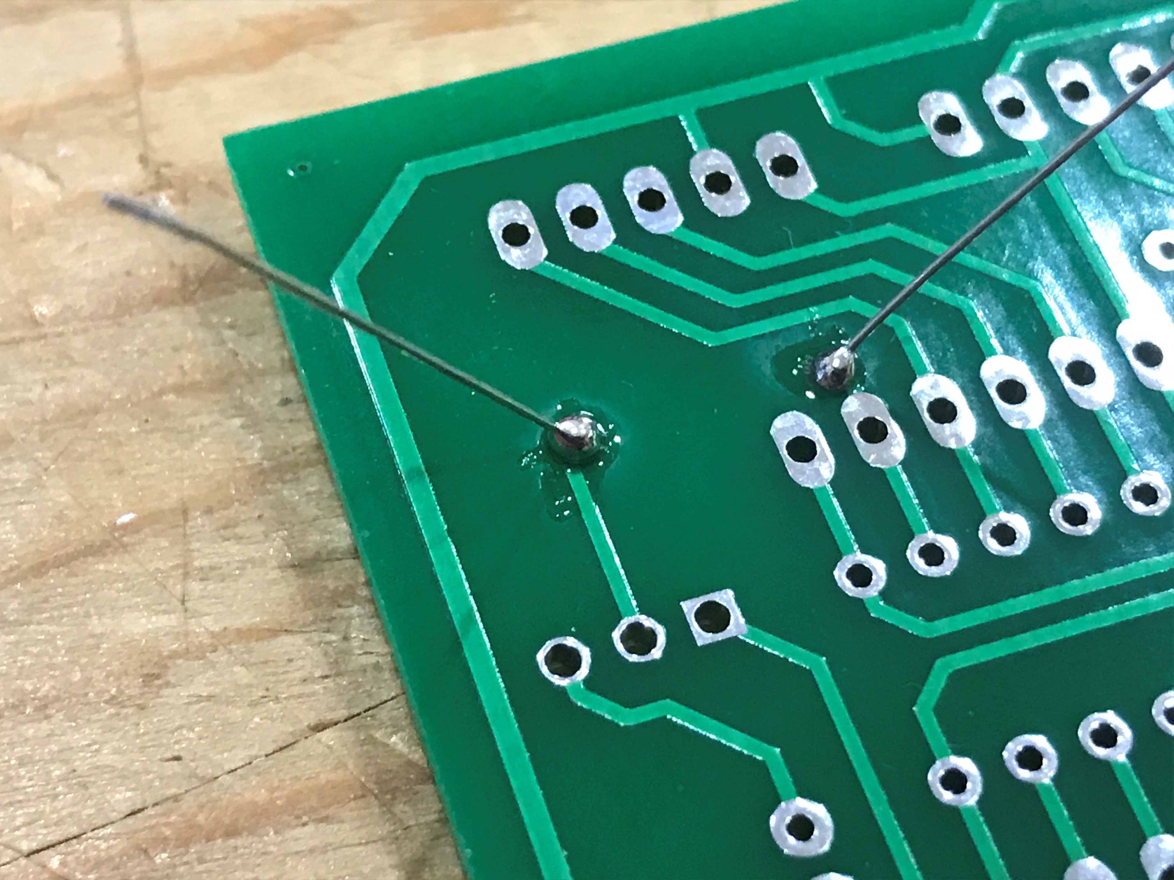
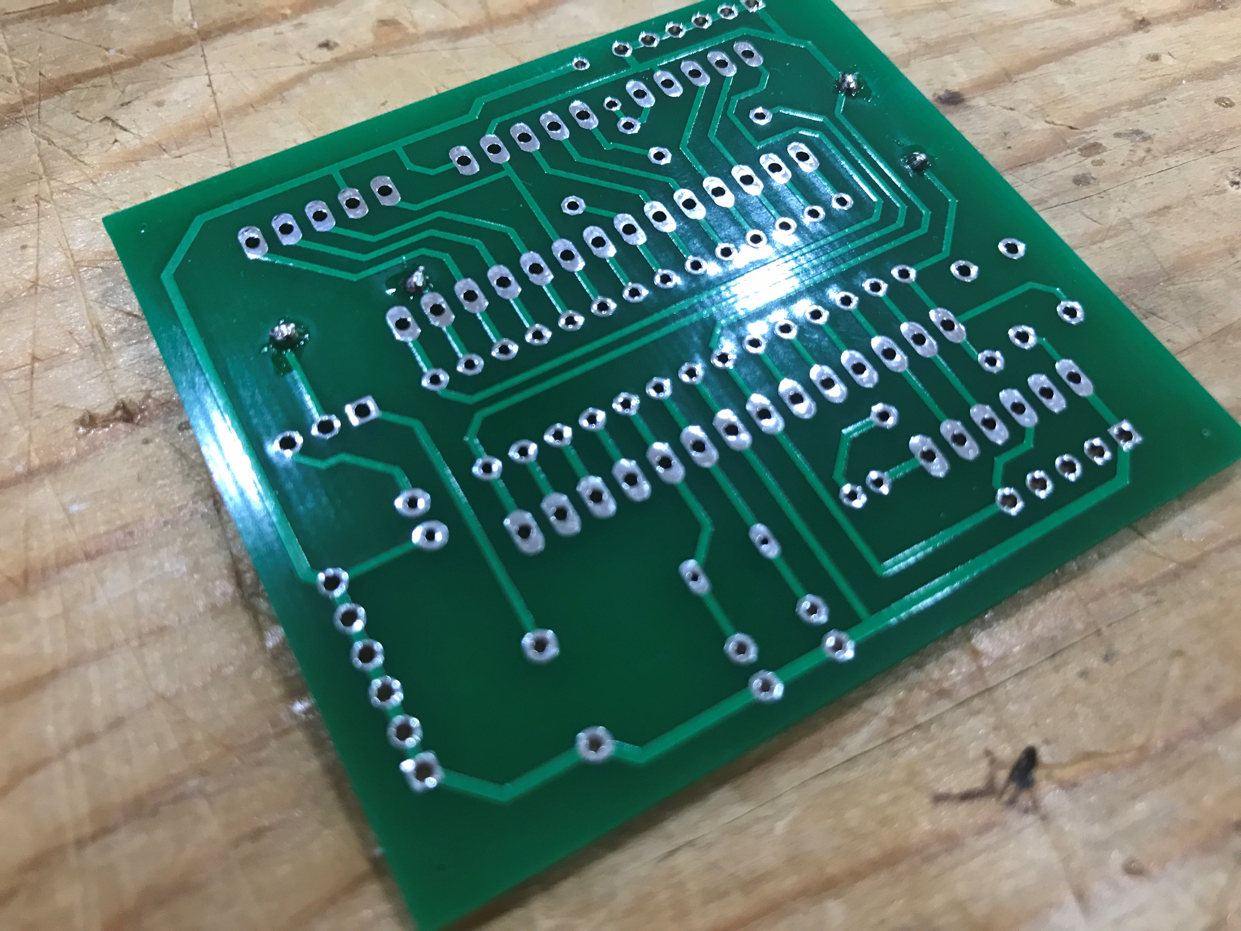
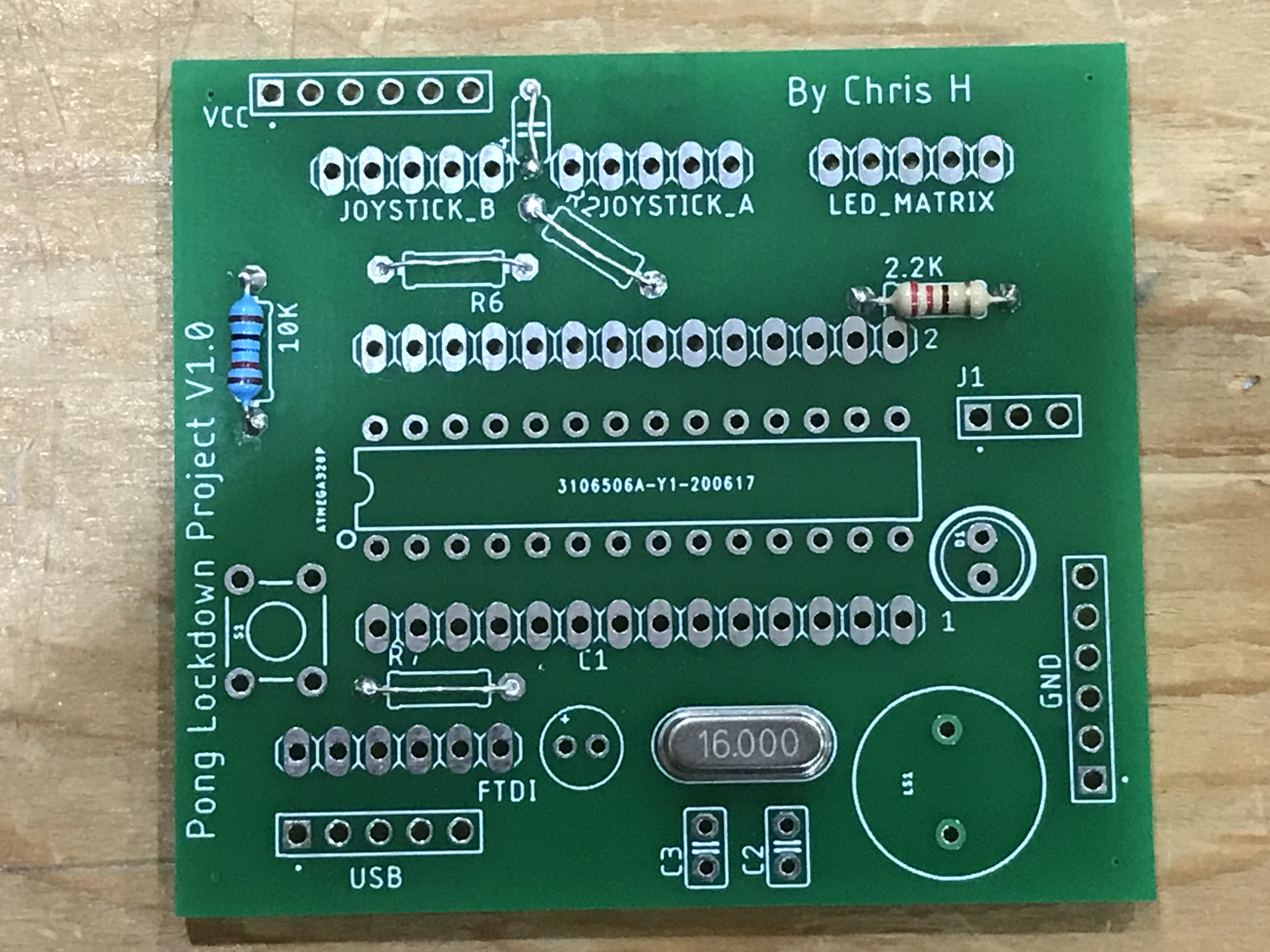
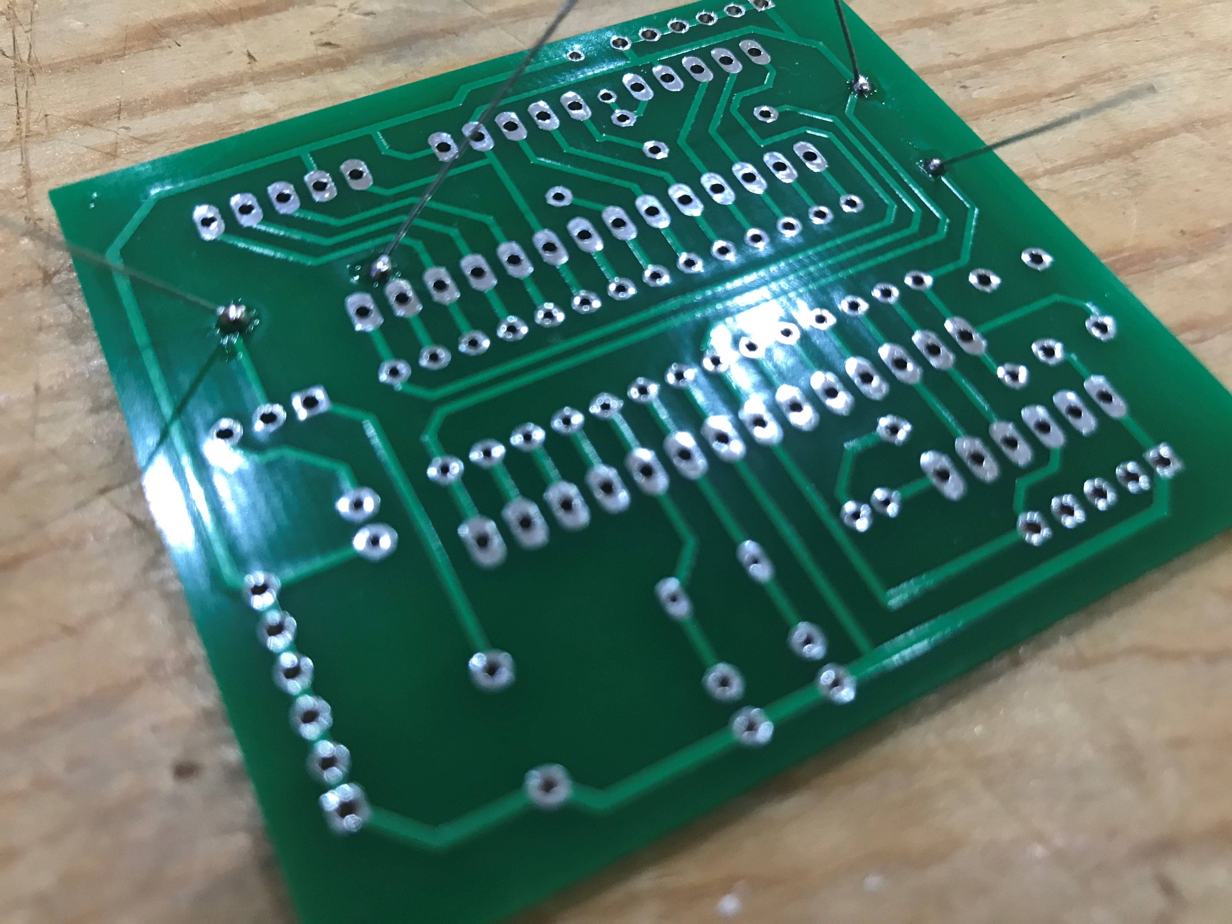
Solder the shortest components first starting with the resistors, then the capacitor and then the crystal.
To do this poke the legs through the holes of the PCB where the markings say, be careful of the polarity on the capacitor, one side of the board has a + symbol for the longer, positive leg of the capacitor.
Hold the soldering iron on the solder pad and leg of the component and then touch the solder onto the joint.
Taller Components: LED, Button, Capacitor and IC Socket
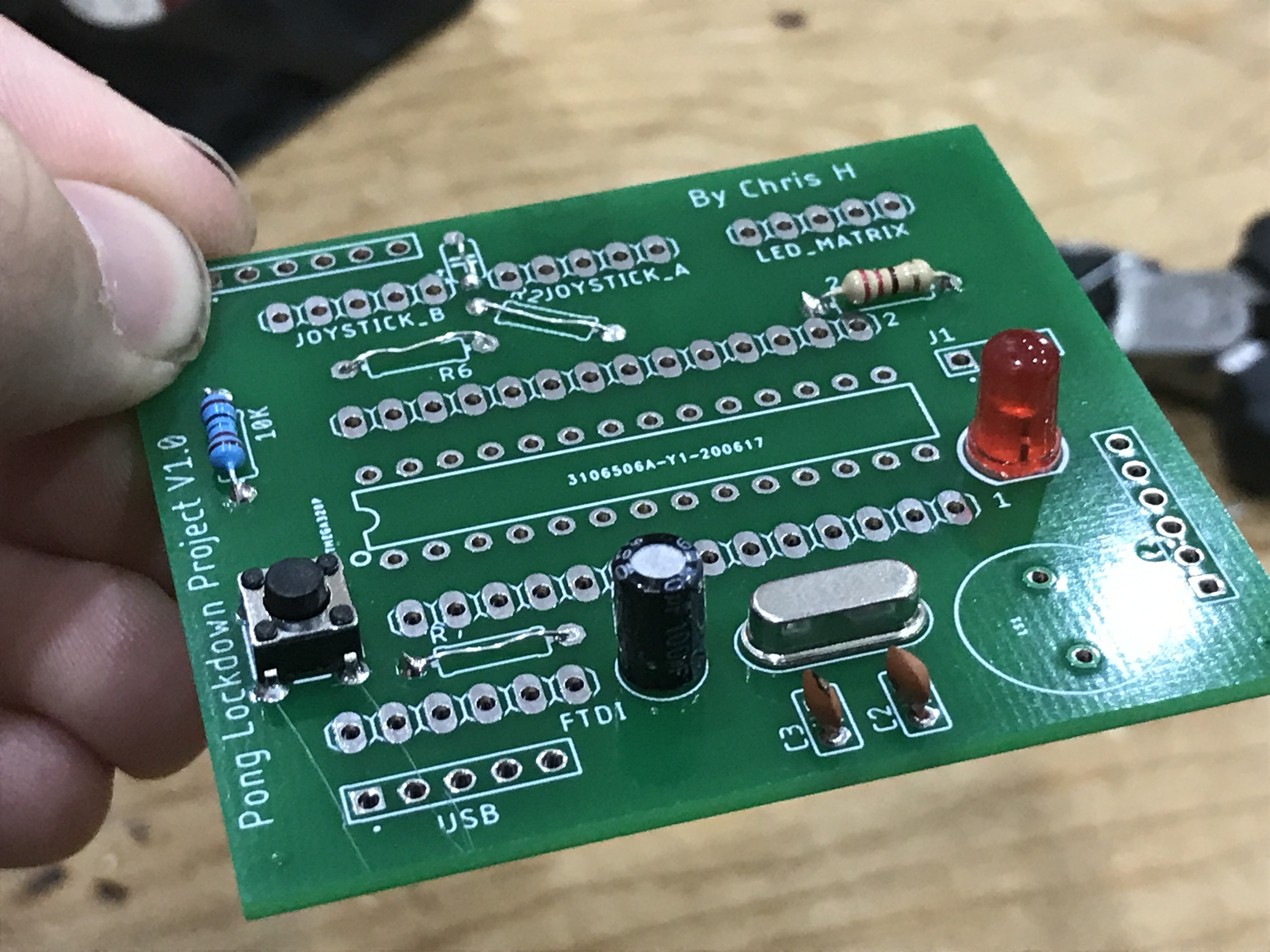
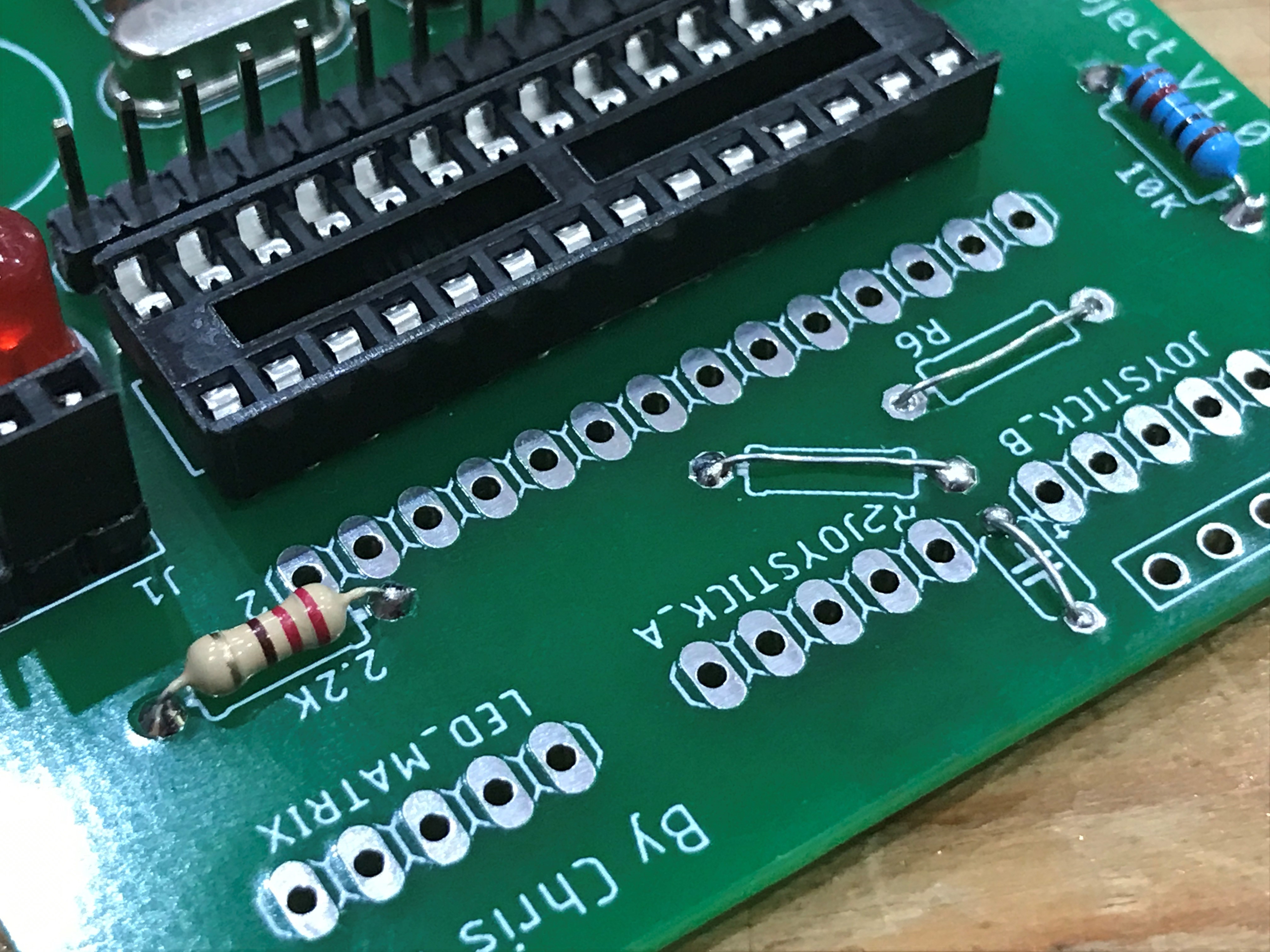
Now solder the taller components such as the LED, pushbutton and IC socket.
Headers
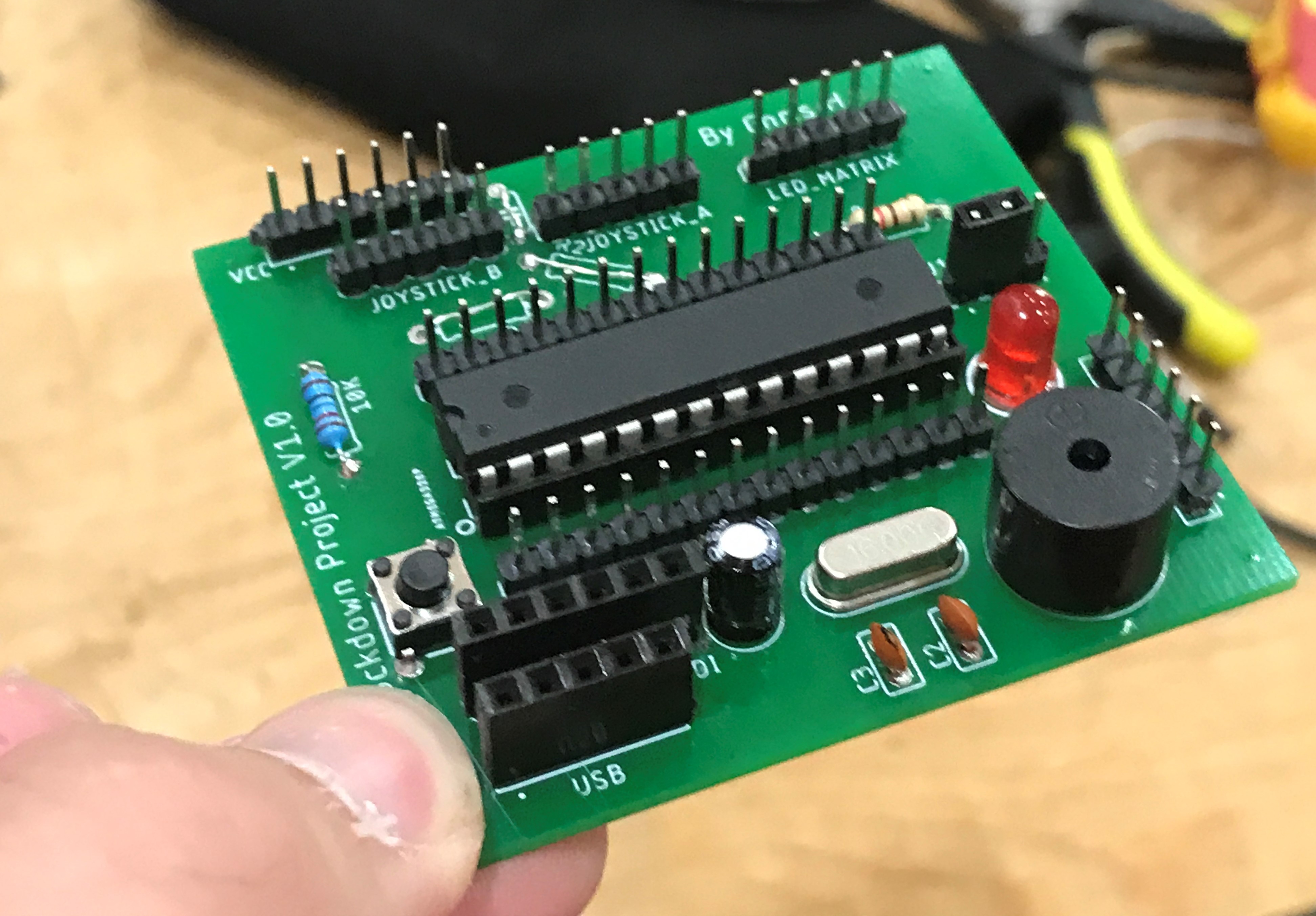
Finally you can solder the headers and buzzer on to the board and that's it!
All that's left to do is push the 328P IC into the socket and connect power either using the GND and VCC headers or by plugging in an FTDI USB board to the 6-pin female header or a 5 pin micro USB board into the 5 pin header.
How to Program
I recommend that you plug the IC into an Arduino Uno in the same way as usual to program it, however if you want to program the Atmegs328P in the board you can do this with a USB FTDI module plugged into the 6-Pin Female Header.
Wire External Components
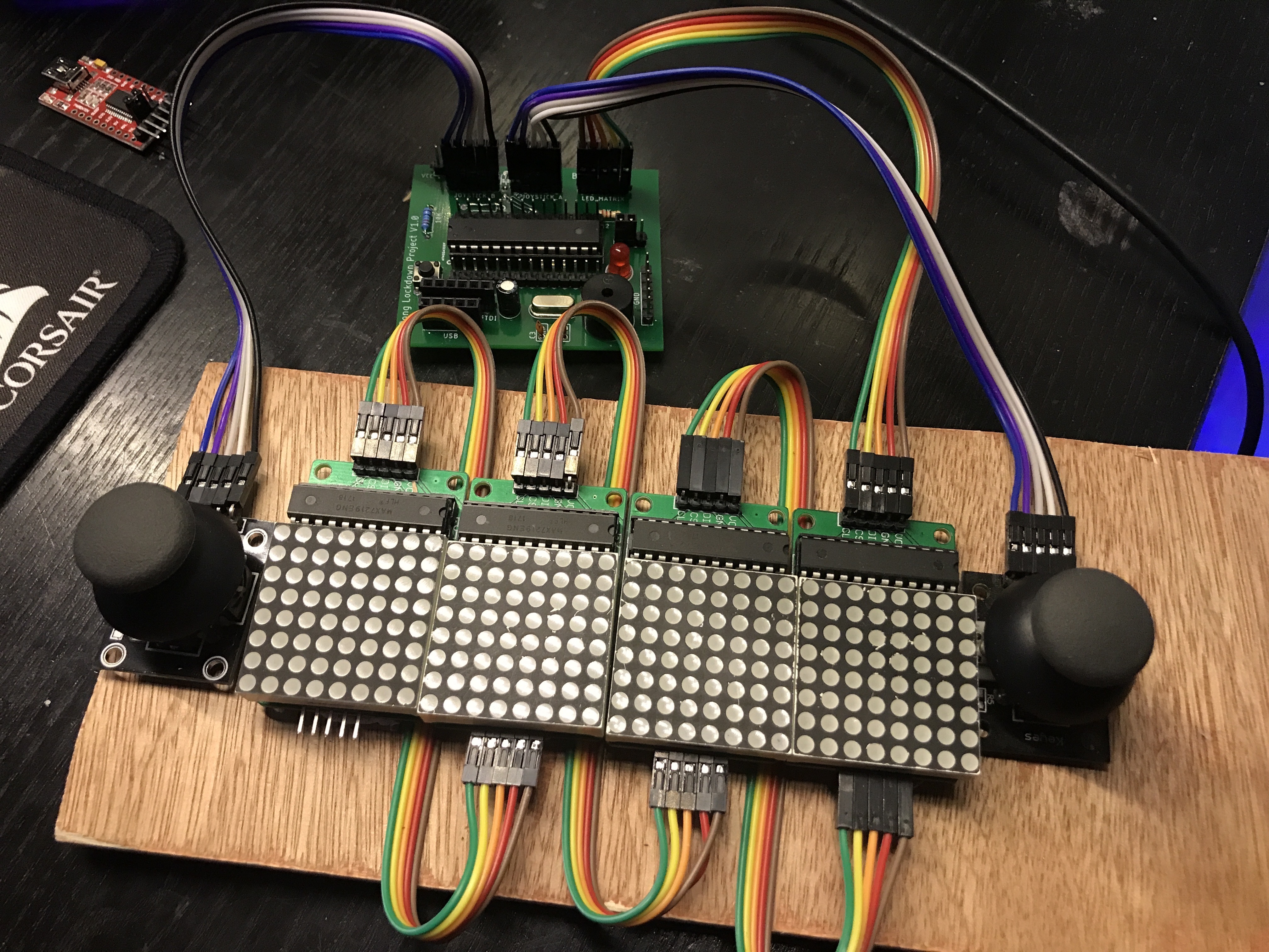
Now the PCB is finished you can connect the two joysticks and LED matrices to the labelled headers at the top of the board and have fun playing your first round of Pong!
Thank You
Thank you for reading, if you would like to recreate this project or modify it I have attached the eagle files you'll need to order your own PCB. You can also find the code in the linked Instructable about prototyping this project. I hope you enjoy making your own PCB its an interesting and exciting project.