Arduino Photo Interrupter Module
by Utsource in Circuits > Arduino
961 Views, 0 Favorites, 0 Comments
Arduino Photo Interrupter Module
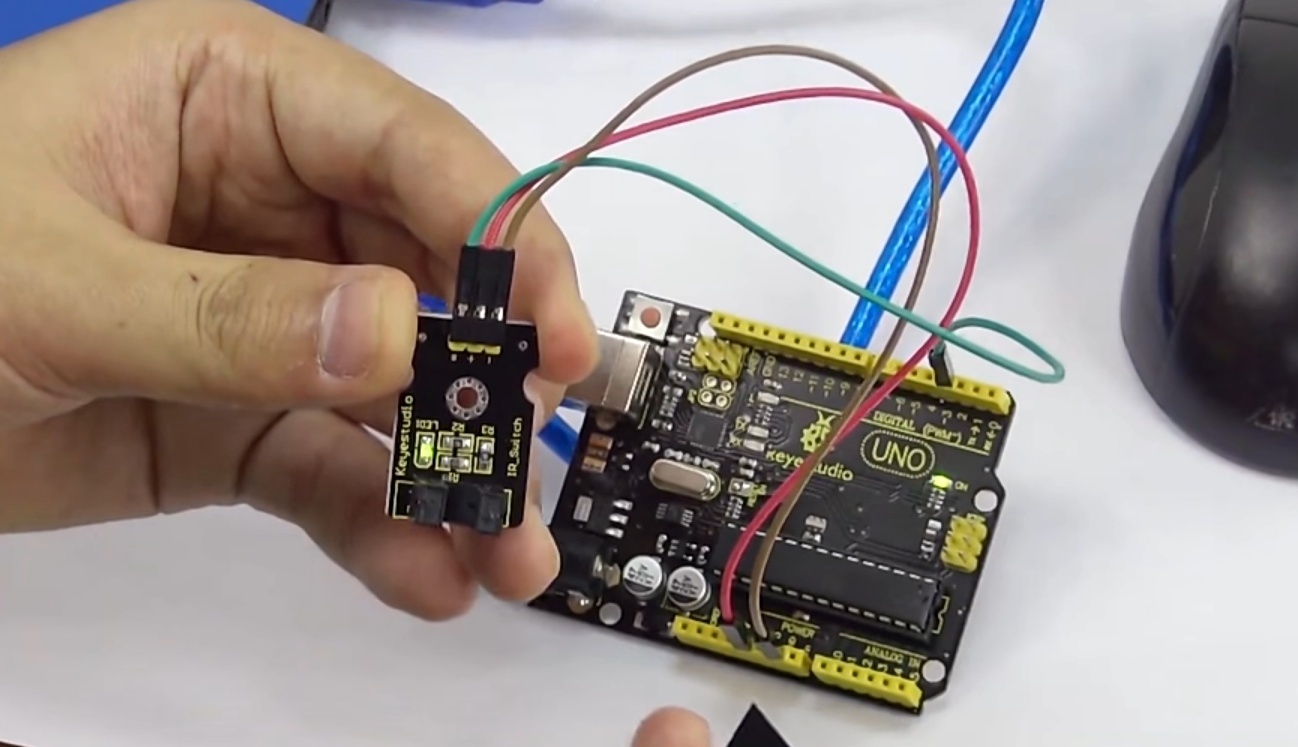
Hi guys in this instructables we will learn how to use Photo Interrupter module with Arduino.
Photo Interrupter Module Keyes KY-010 for Arduino, will trigger a signal when light between the sensor's gap is blocked.
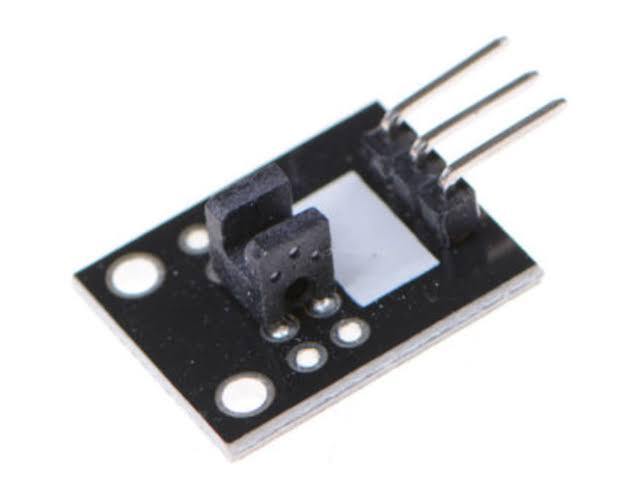
THe KY-010 Photo Interrupter module consists of an optical emitter/detector in the front and two resistors (1 kΩ and 33 Ω) in the back. The sensor uses a beam of light between de emitter an detector to check if the path between both is being blocked by an opaque object.
Photo Interrupter Module Keyes KY-010 for Arduino, will trigger a signal when light between the sensor's gap is blocked.
THe KY-010 Photo Interrupter module consists of an optical emitter/detector in the front and two resistors (1 kΩ and 33 Ω) in the back. The sensor uses a beam of light between de emitter an detector to check if the path between both is being blocked by an opaque object.
Things You Need
.jpg)
For this instructables we will need following things :
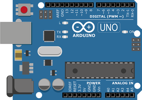
Arduino uno
Photo Interrupter module
Jumper wires
Breadboard (optional)
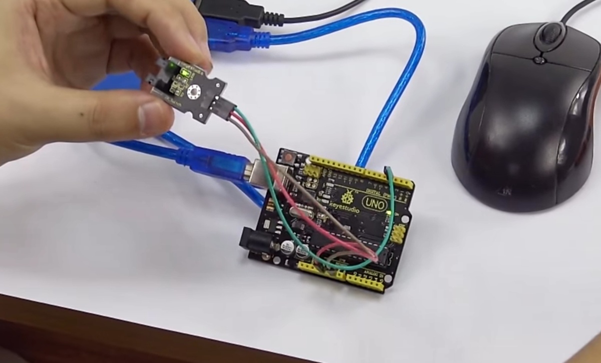
Schmatics
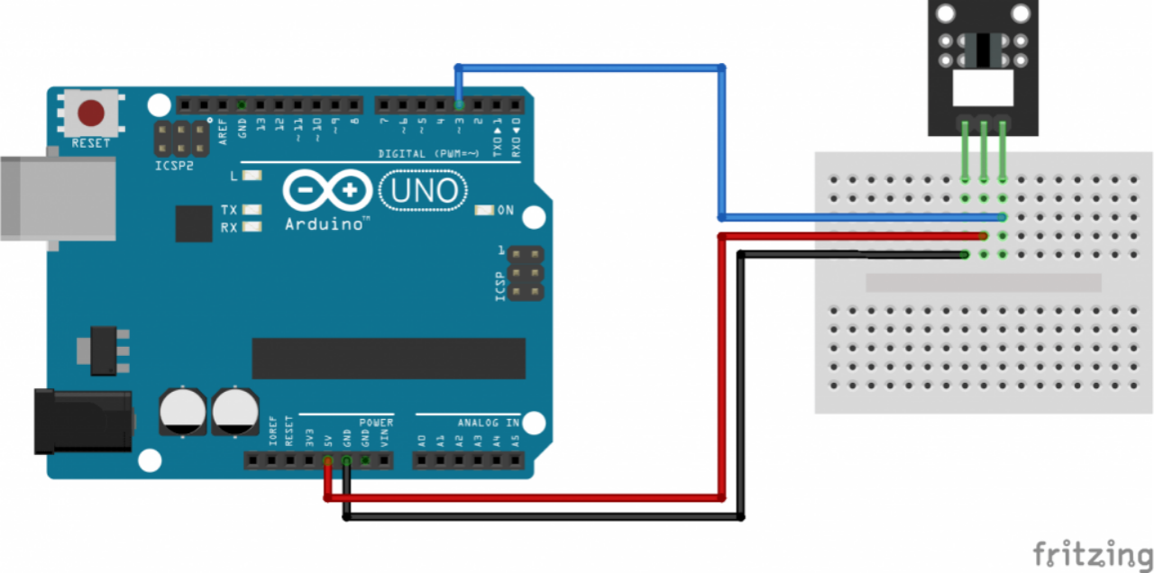
Connect the power line (middle) and ground (left) to +5V and GND respectively. Connect signal (S) to pin 3 on the Arduino.
KY-010 - Arduino
- (left) - GND
middle - +5V
S (right) - Pin 3
KY-010 - Arduino
- (left) - GND
middle - +5V
S (right) - Pin 3
Code
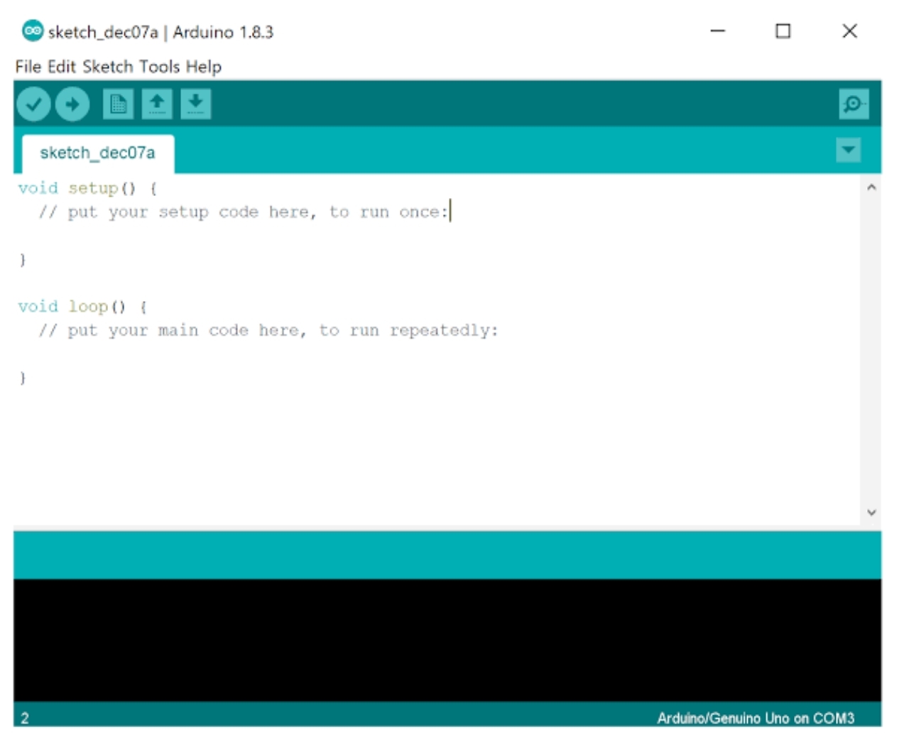
Please copy the following code and upload it to your arduino Board :
int Led = 13; // define LED pin
int buttonpin = 3; // define photo interrupter signal pin
int val; //define a numeric variable
void setup()
{
pinMode(Led, OUTPUT); // LED pin as output
pinMode(buttonpin, INPUT); //photo interrupter pin as input
}
void loop()
{
val=digitalRead(buttonpin); //read the value of the sensor
if(val == HIGH) // turn on LED when sensor is blocked
{
digitalWrite(Led,HIGH);
}
else
{
digitalWrite(Led,LOW);
}
}
Testing Photo Interrupter Module
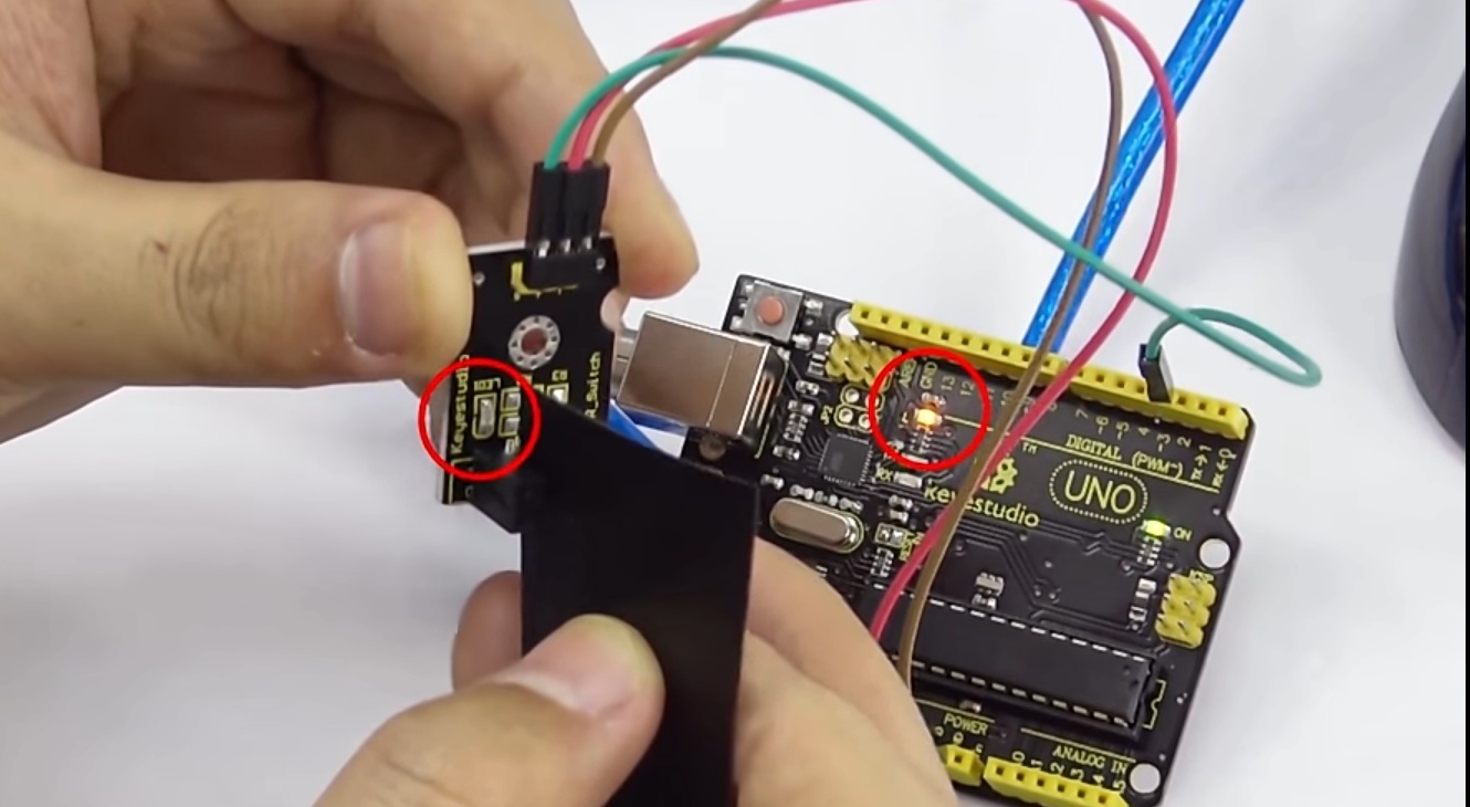
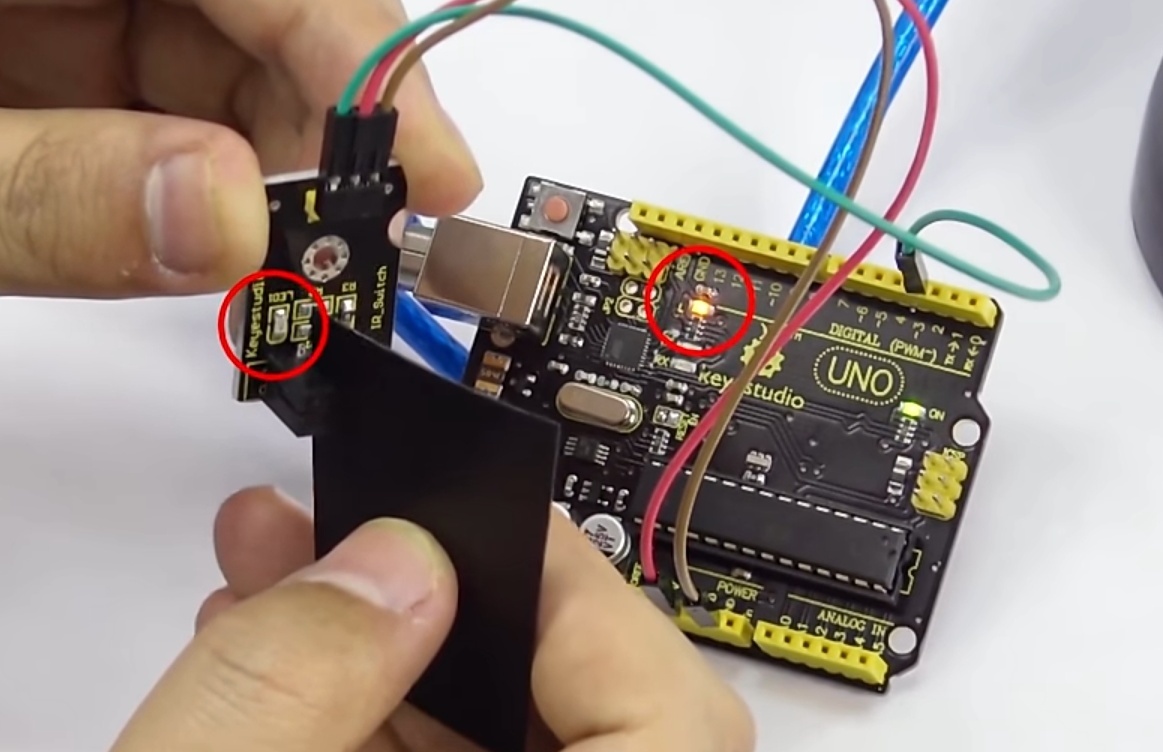
The arduino will light up the LED (pin 13) on the Arduino when there's an object blocking the beam of light between the sensor's gap.