Arduino Oled Elipse Scale
by cristinepotu7171 in Circuits > Arduino
3069 Views, 9 Favorites, 0 Comments
Arduino Oled Elipse Scale
In this tutorial we build an ellipsoidal scale with Arduino
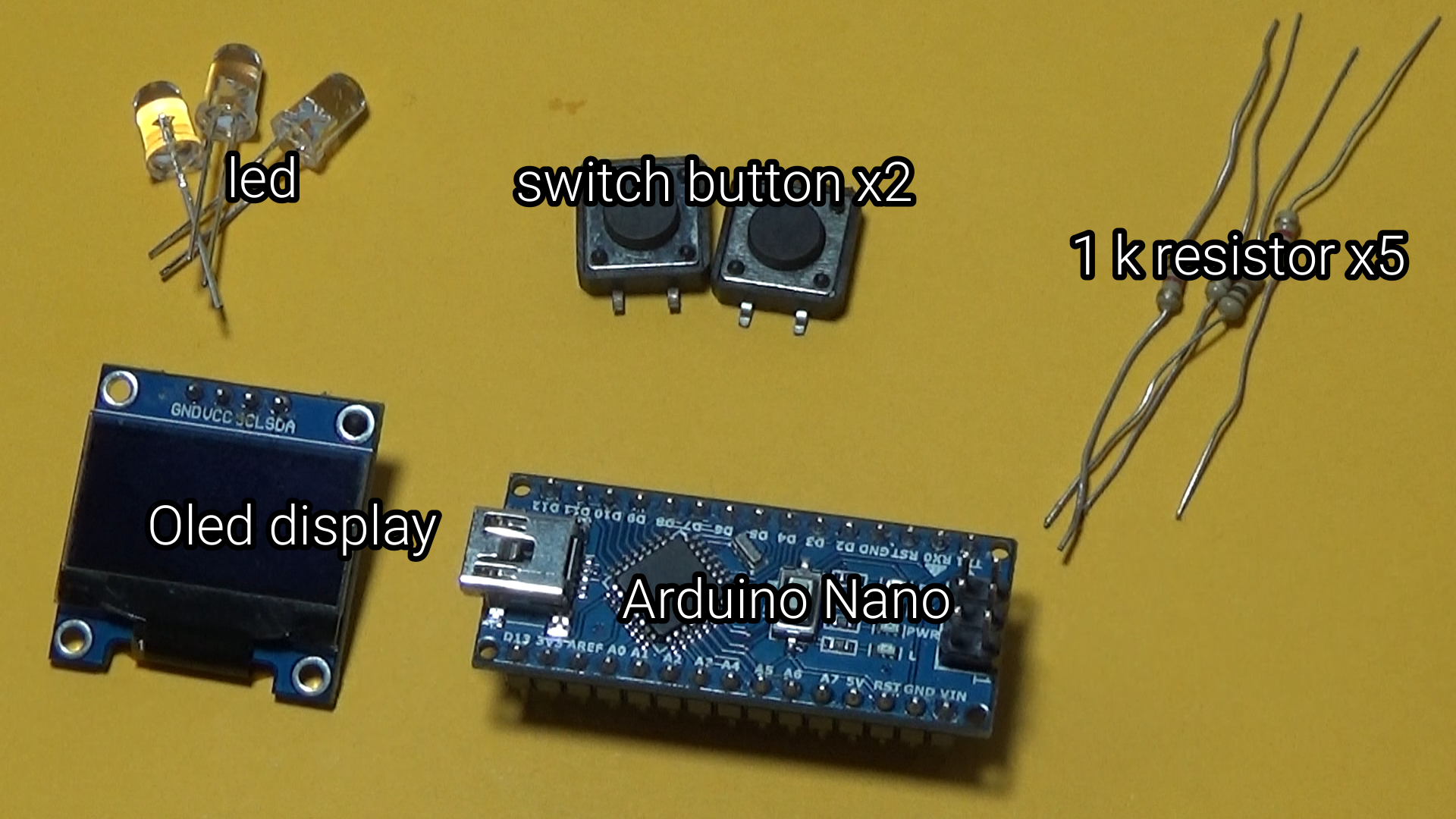
Supplies
.jpg)

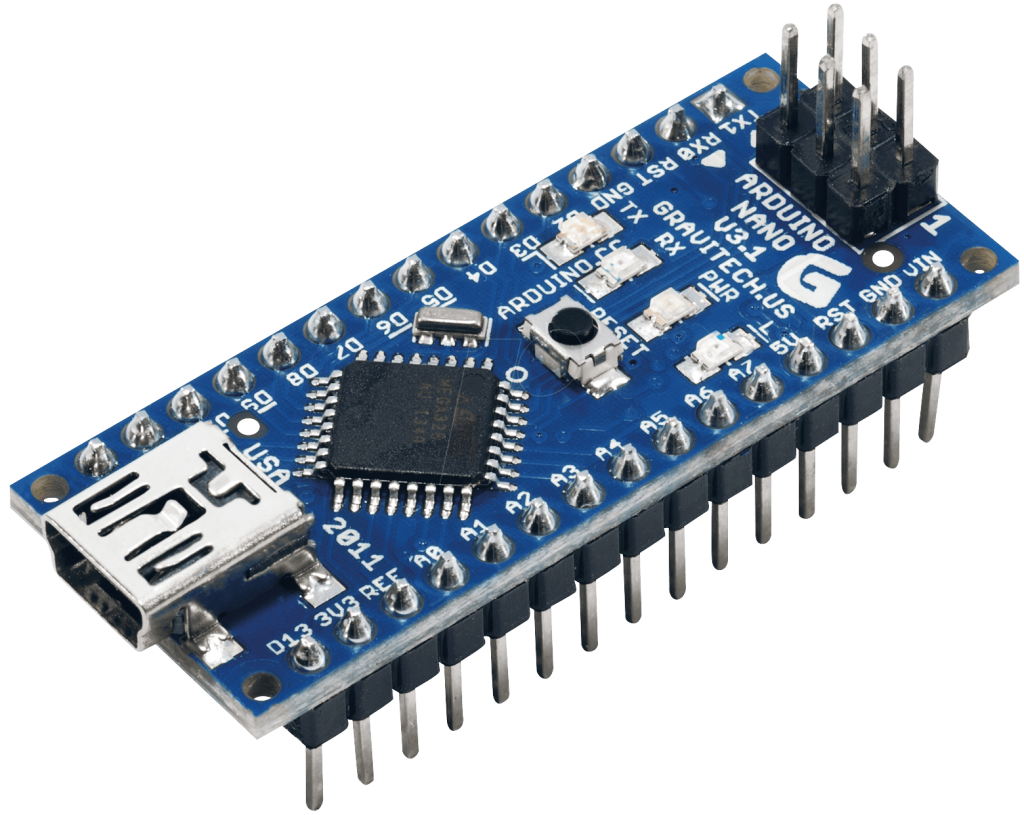
- Arduino Nano
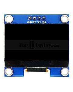
- Oled display 64x128
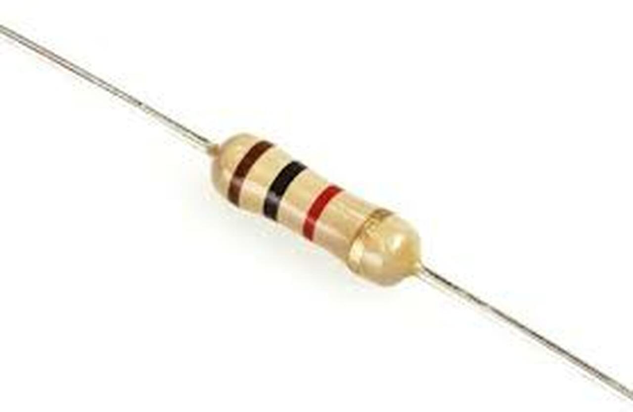
- 1k resistor x5
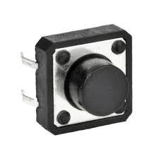
- push button x2
- Visuino software
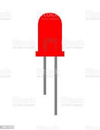
- Led x3
Schematic Diagram
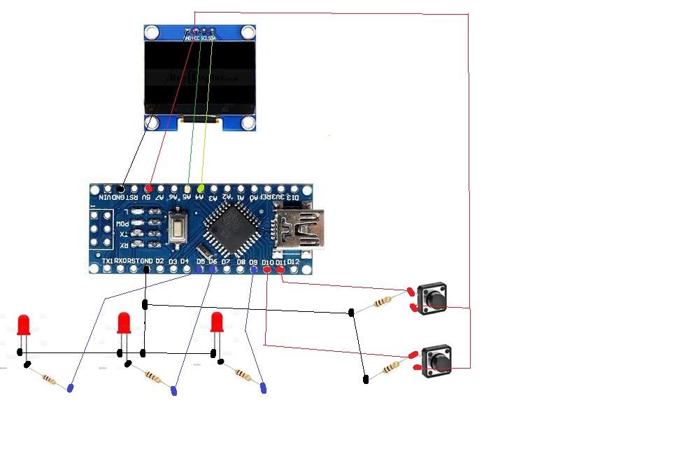
Make the connections of the components according to the diagram below
Construction
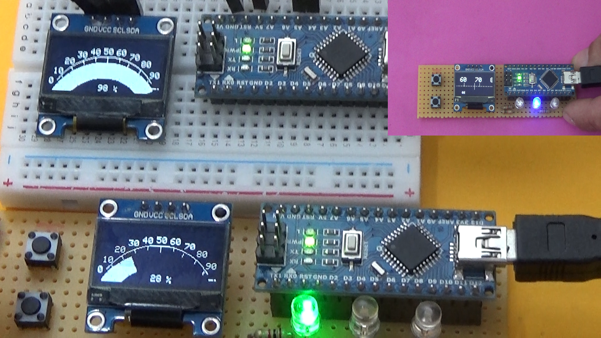
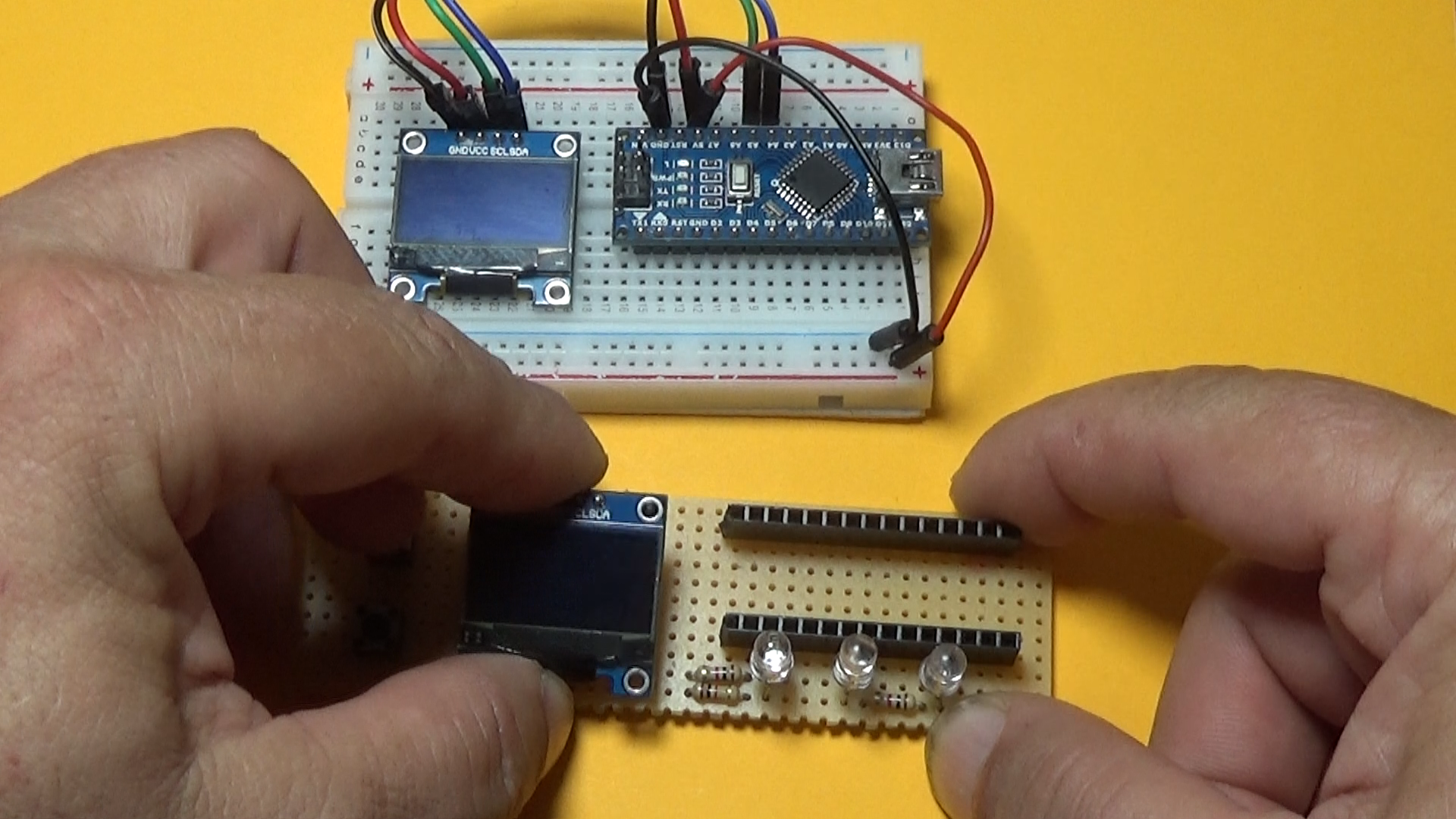
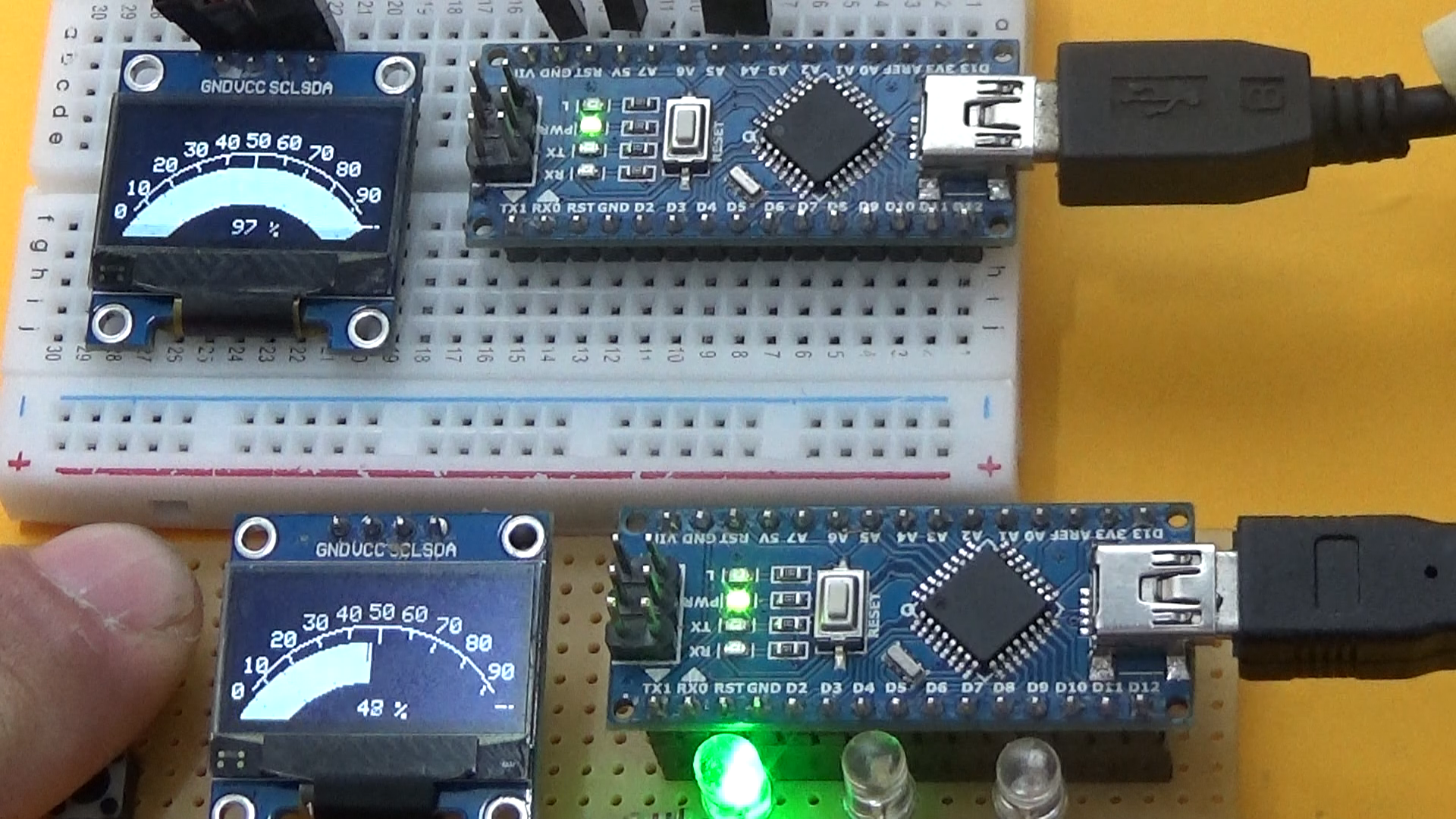
we can build the assembly on test wiring or breadboard following the wiring diagram
Upload Sofware in Arduino
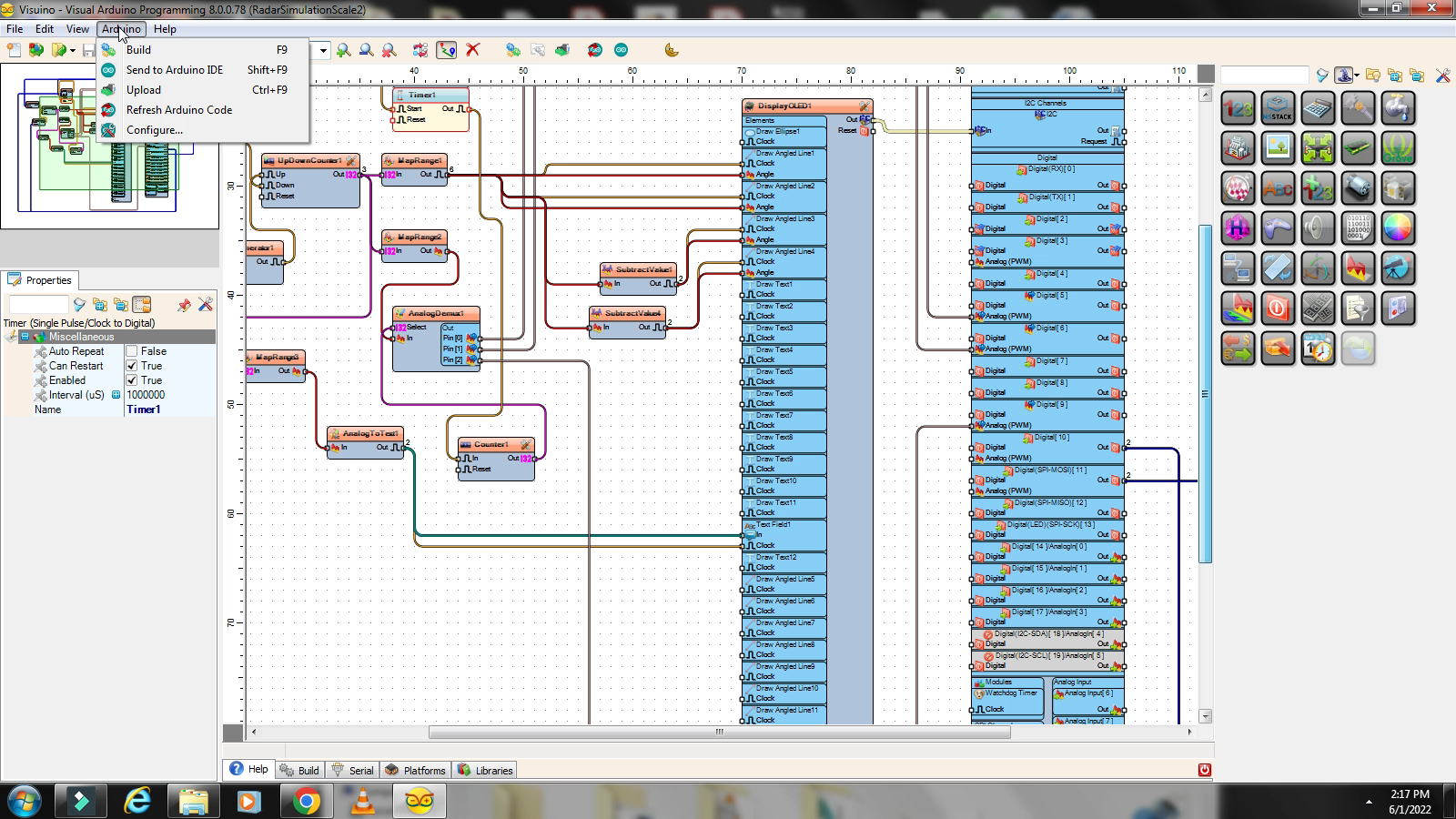
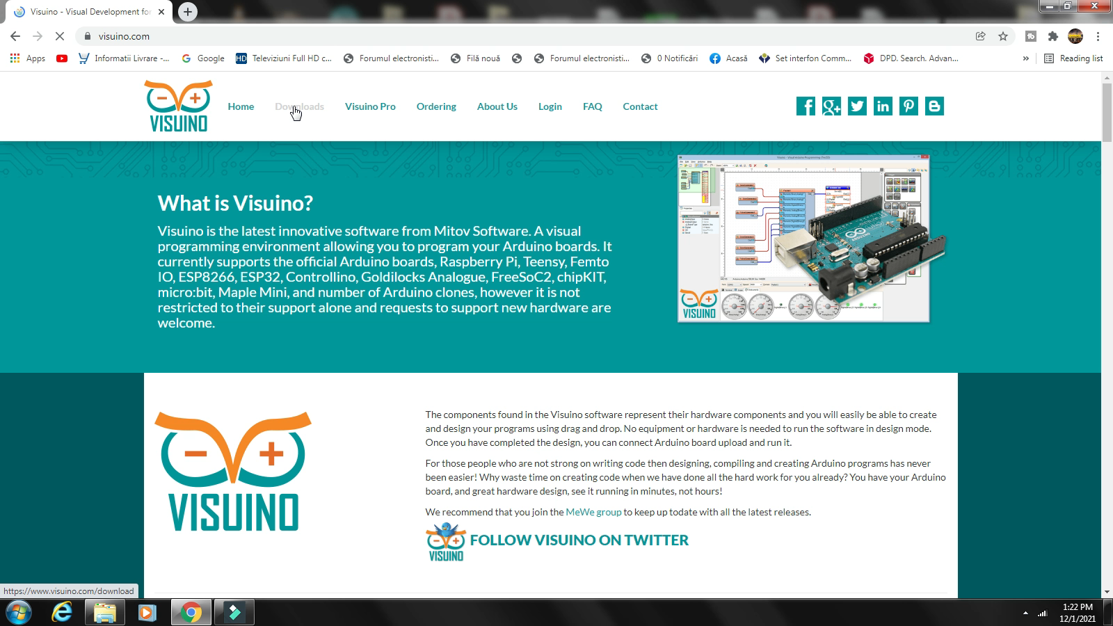
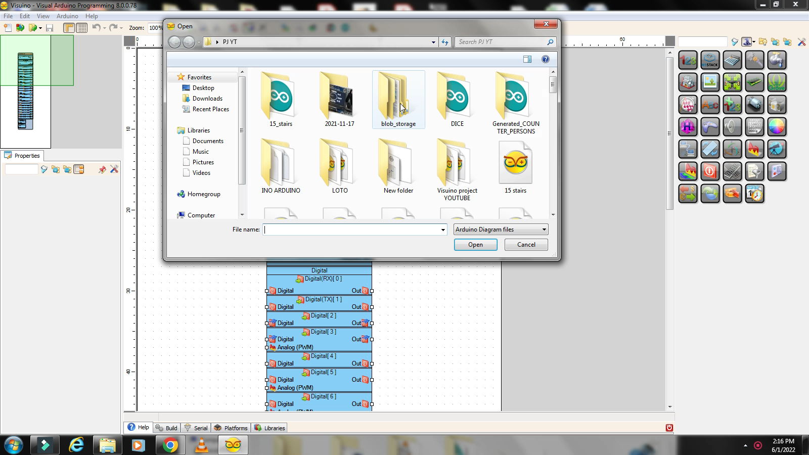
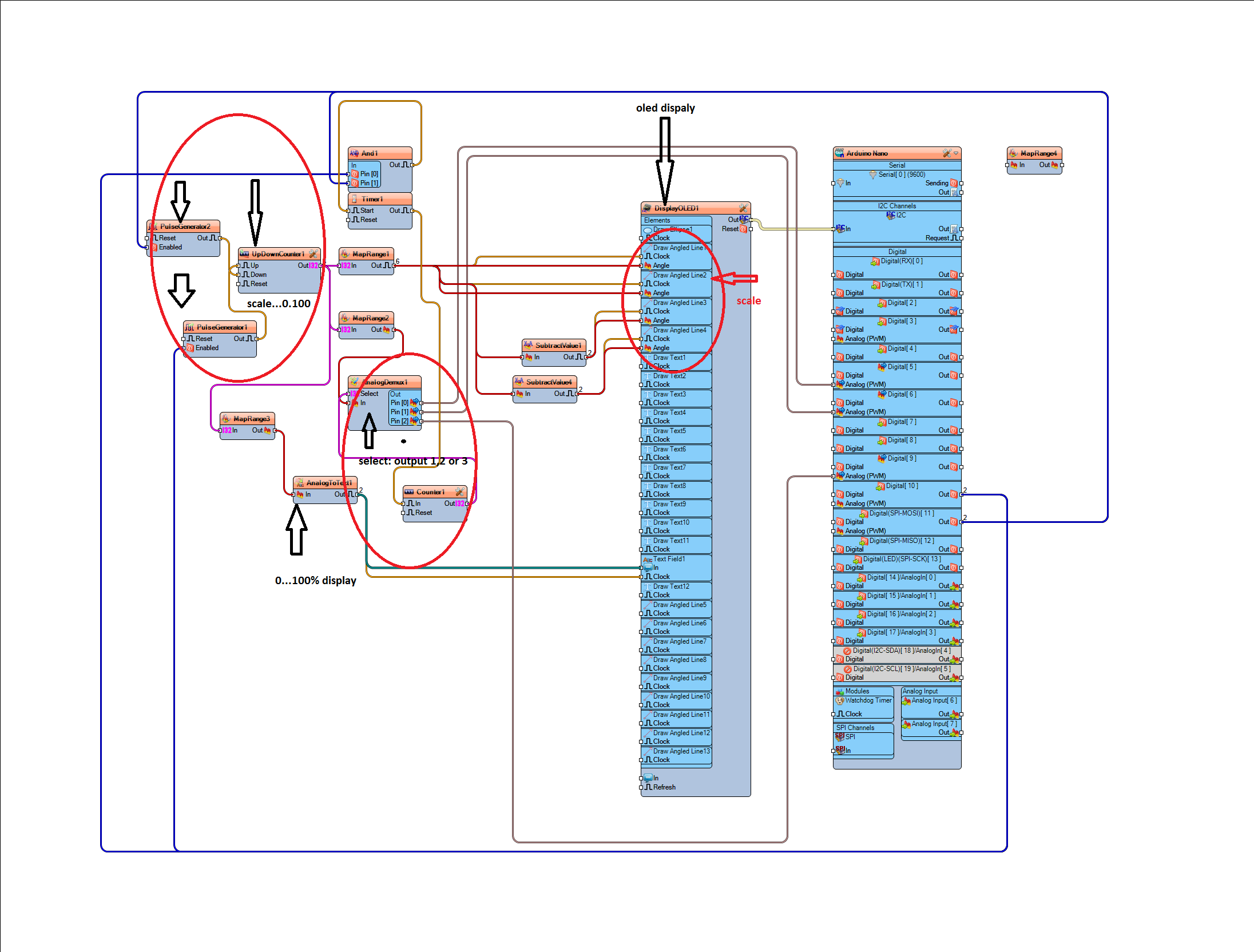
In this step we run the code in Visuino and load it in the Arduino board. It is necessary to download the latest version of Visuino. In the photos you have explained the general compilation scheme. Also find in the attachment the codes in Visuino and skecth format, for a single controlled output, for 3 controlled outputs, with elipse line, without elipse line. Download Visuino: https://www.visuino.com/download
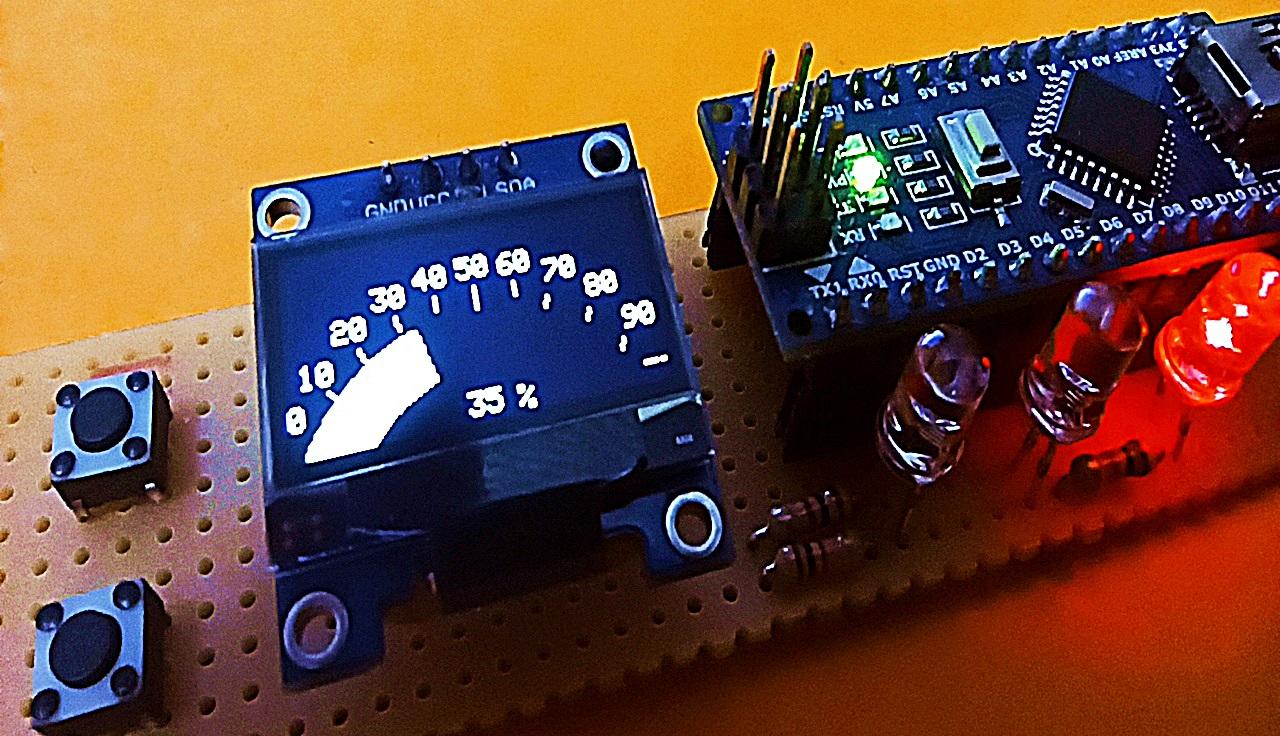
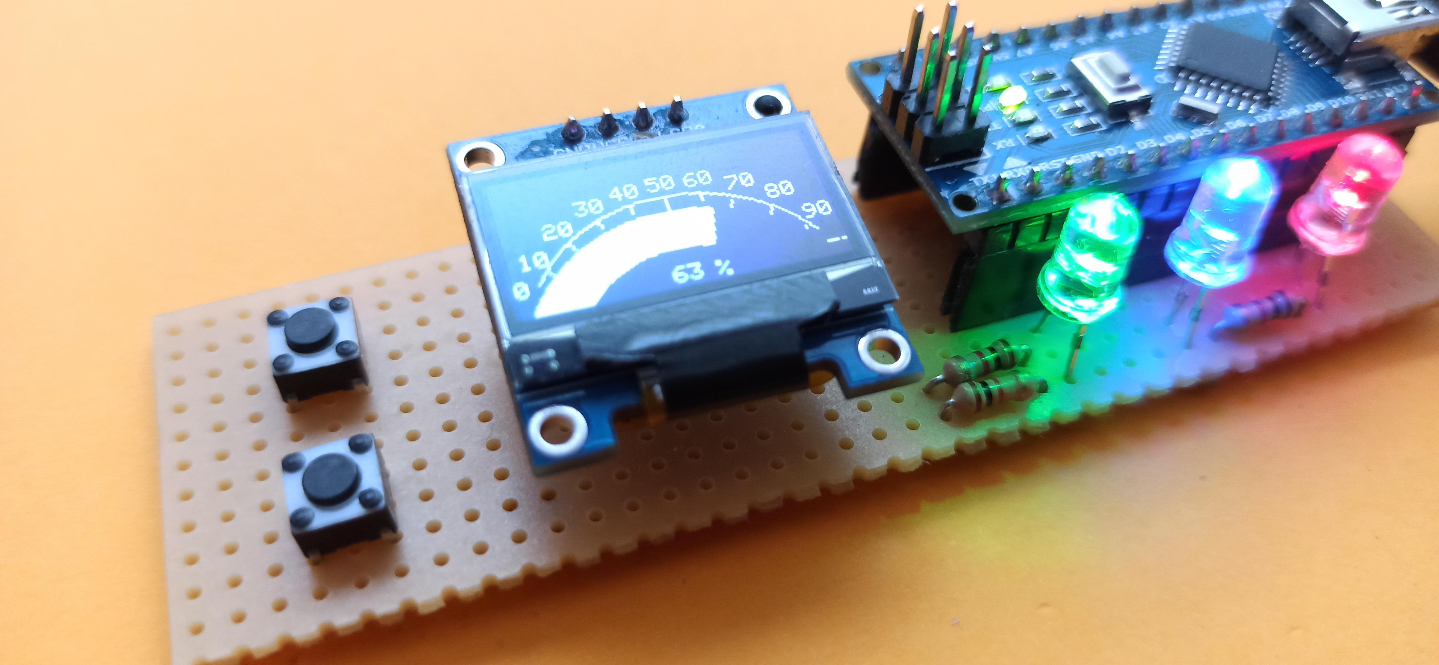
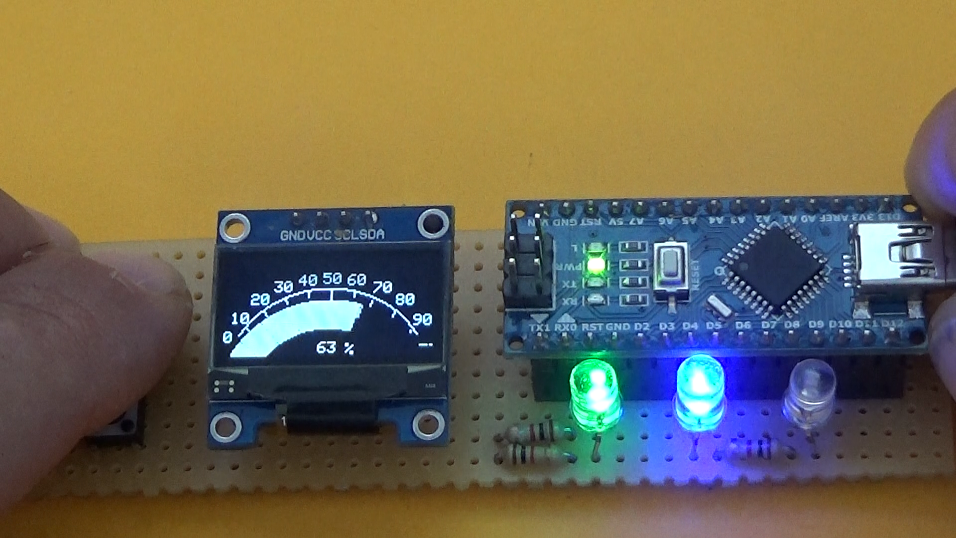
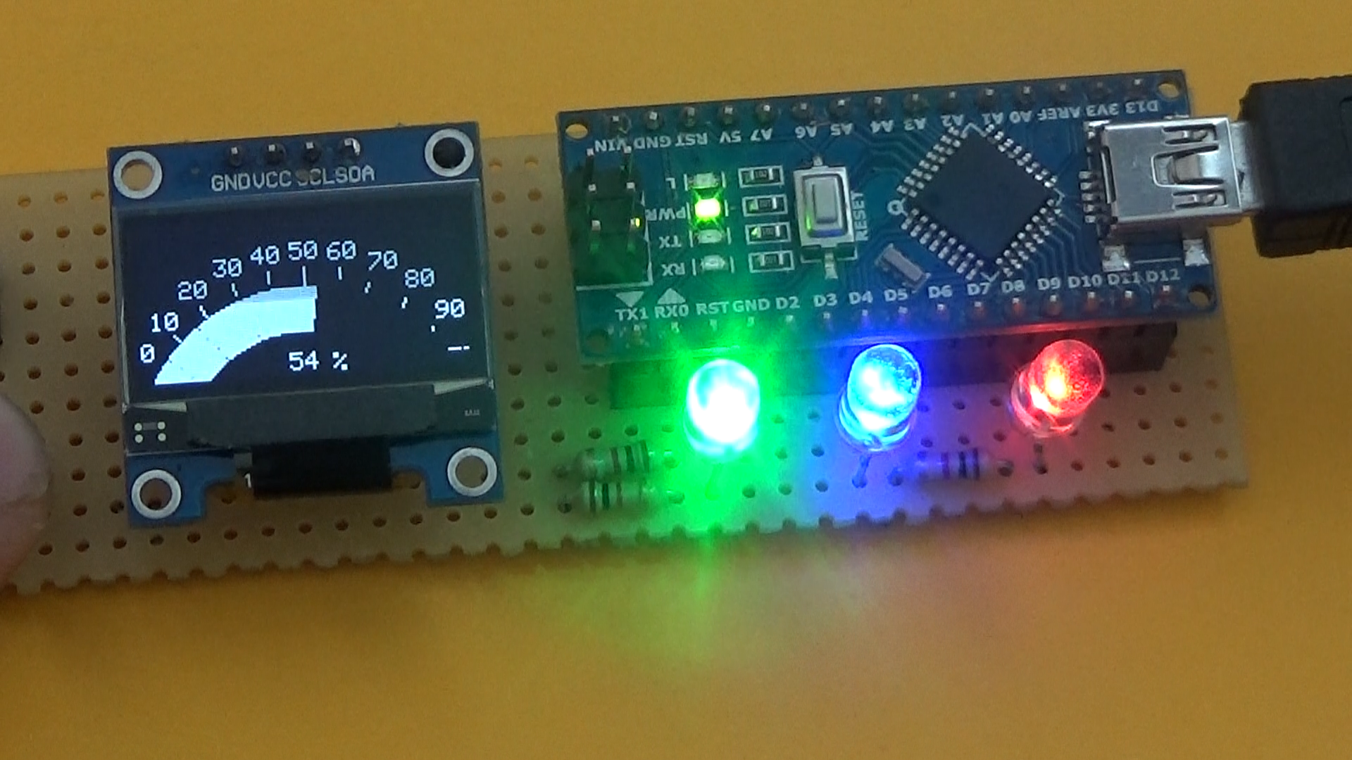
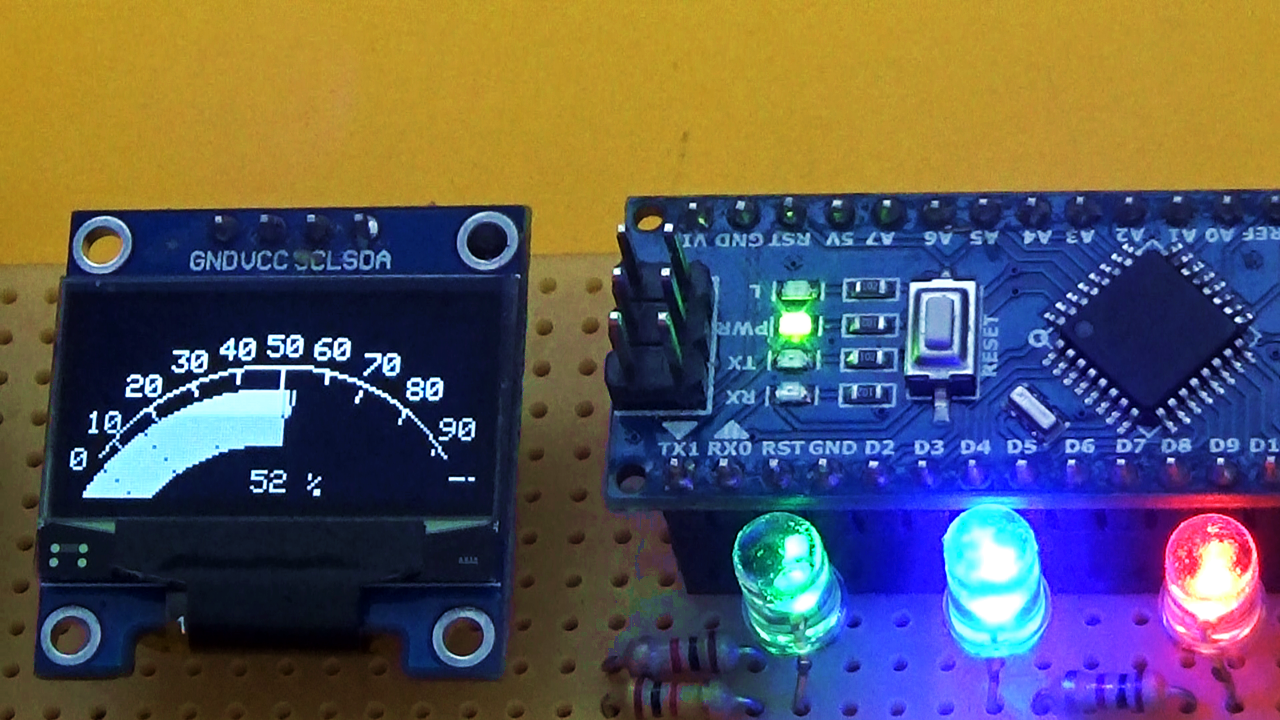
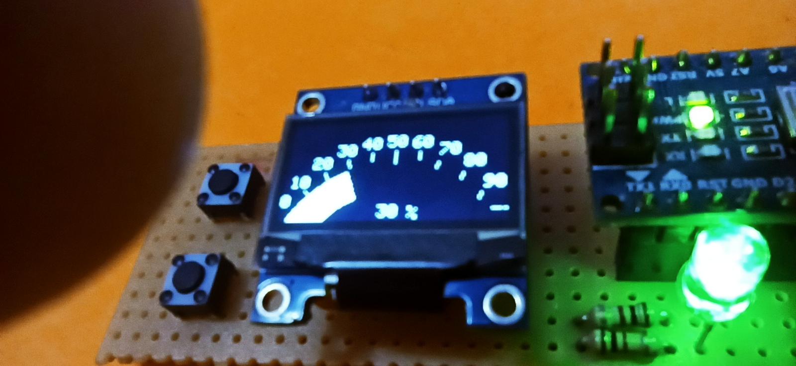
Strat the Device
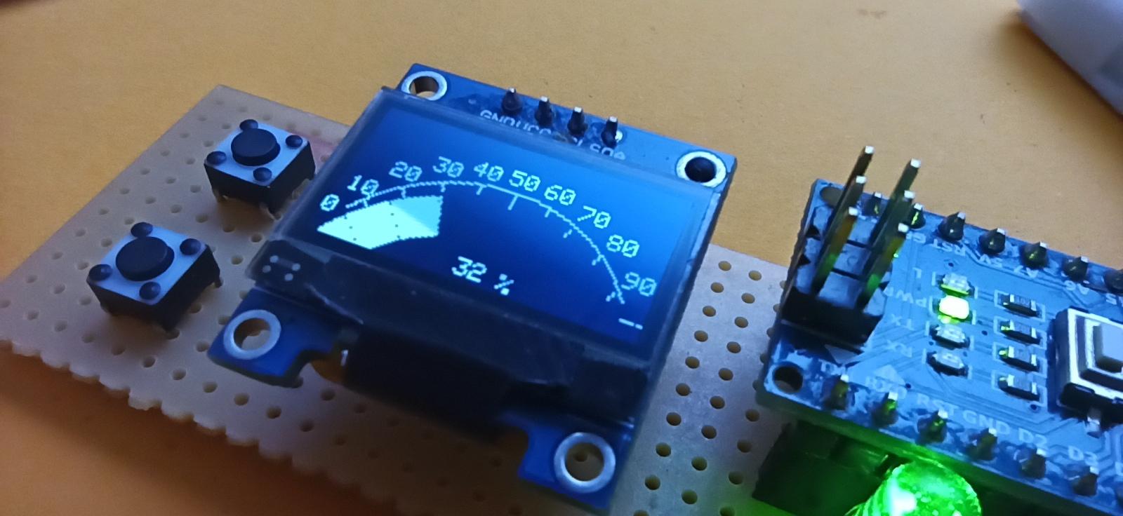
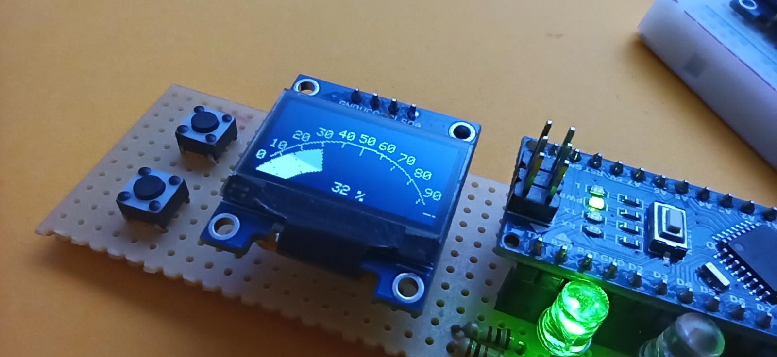
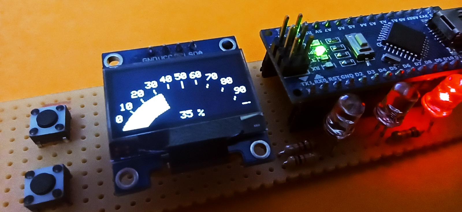
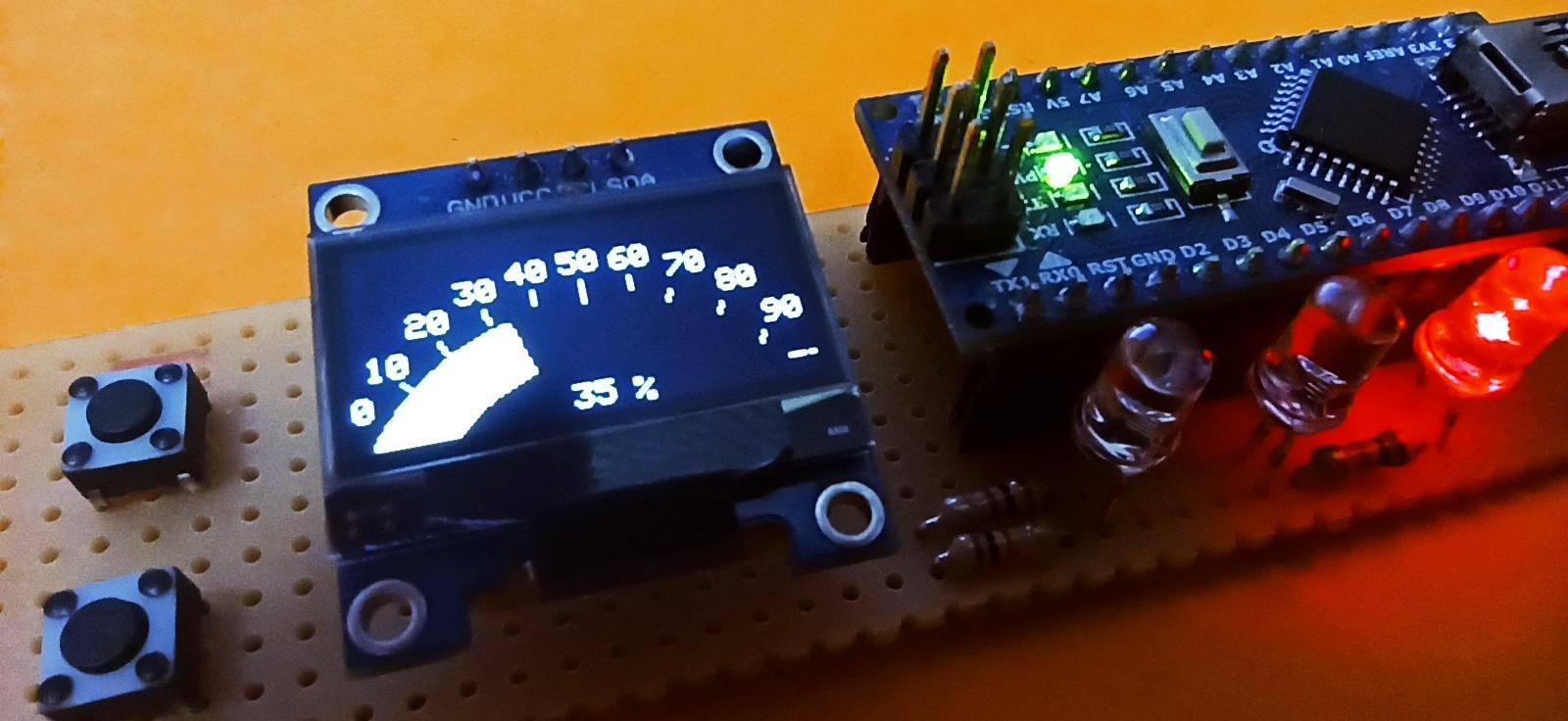
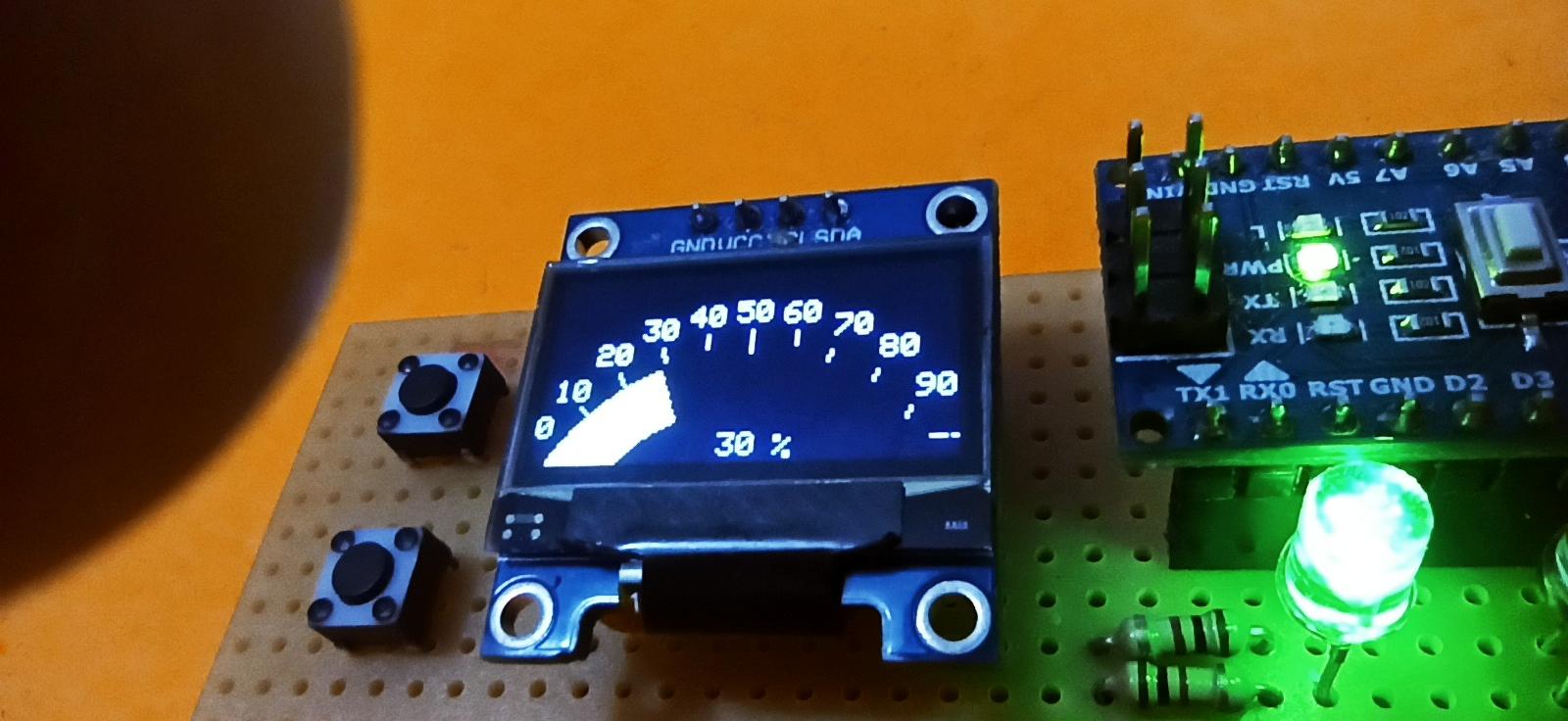


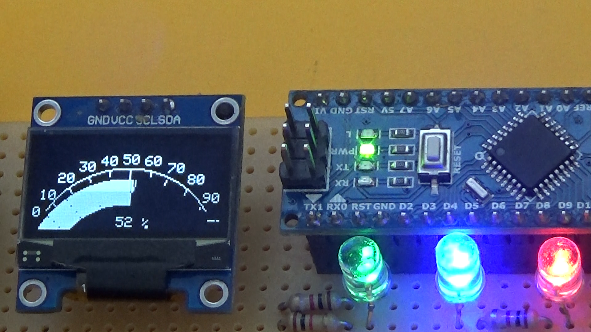
Connect the USB cable to a power source. The device will immediately display the scale with or without the ellipse depending on the loaded code. We press the 'up' button and the scale will advance to 100%. At the same time, the PWM output will increase in intensity. For the 'down' button, pwm will decrease in intensity in conjunction with lowering the scale to 0. I hope you enjoyed my tutorial, good luck to everyone!