Arduino Obstacle Avoiding Motor Powered Car
by 665568 in Circuits > Arduino
1213 Views, 2 Favorites, 0 Comments
Arduino Obstacle Avoiding Motor Powered Car
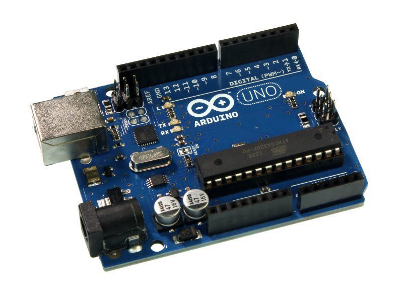
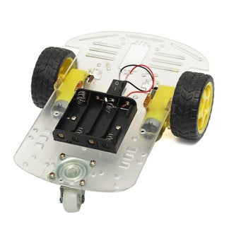
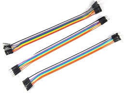
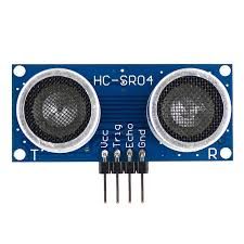
Hello! and welcome to the tutorial regarding how to construct an Arduino obstacle avoiding car. We can get started by obtaining the necessary materials for this project, and make sure to have fun!
MATERIALS:
- Female to Male Wires
- Wires
- Distance Sensor
- Wooden Plank
- Gorilla Tape/Electrical
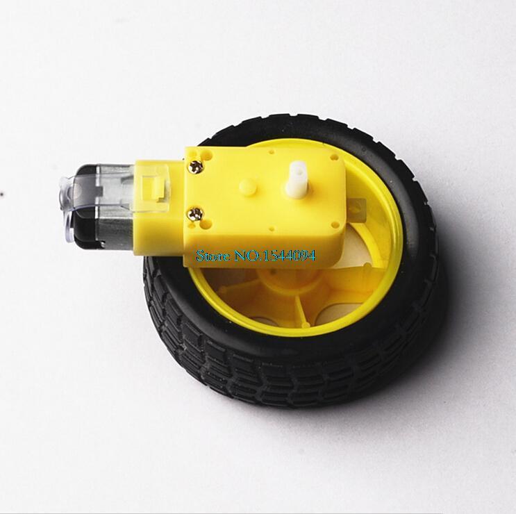
- 2 Motors with Wheels
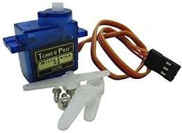
- Servo
- Screwdriver
- Screws
- Arduino
- Battery Holdster
- Wheel
- USB to Battery Pack
- Arduino Motor Attachment
- Arduino USB
- PC
- Plastic Stand
Furthermore, I am here to instruct you about making an Obstacle Avoiding Robot based on Arduino. Below is a step by step guide in constructing this mechanism through every detail. However, this project is a fully capable autonomous robot which can be able to avoid any obstacle which it comes into contact with, to then avoid. The process involves meeting an obstacle while proceeding forward, once faced the object, this robot will automatically stop moving forward and will take a step back. Then, it scans the left/right side to then start moving the more suitable path. The purpose of this Project is to understand the engineering/mechanics behind the concept which connects to our society such as self-driving cars, manufacturing industries, etc.
Constructing the Chassis
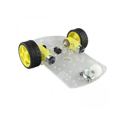
To construct the frame, you will need to get your hands on a premade template for building this project on, or a simple blank of wood with dimensions of 1/2 foot x 1/4 foot. This will be your frame and foundation of this instructable of which your entire arduino code and motors function on.
-
Solder two wires to each DC motor. Then fix two motors to the chassis using the screws.
Using screws/glue/tape, attach the motor to the underside of the chassis on the back portion
Make sure the motors are secure and are able to take force
Take the wheel and using any method, insert the wheel into the front of the project
Attaching Minor Components
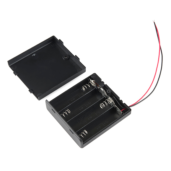
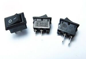
For this step, you will need to place these two components in specific locations to perfect the design of this project. The button will need to be attached to the button by soldering the left port with the red wire from the battery pack holder. Also, utilize tape, glue or screws to set the battery pack in place on the middle portion on the top of your foundation, then attaching the switch to the underside of the project.
Mounting the Modules
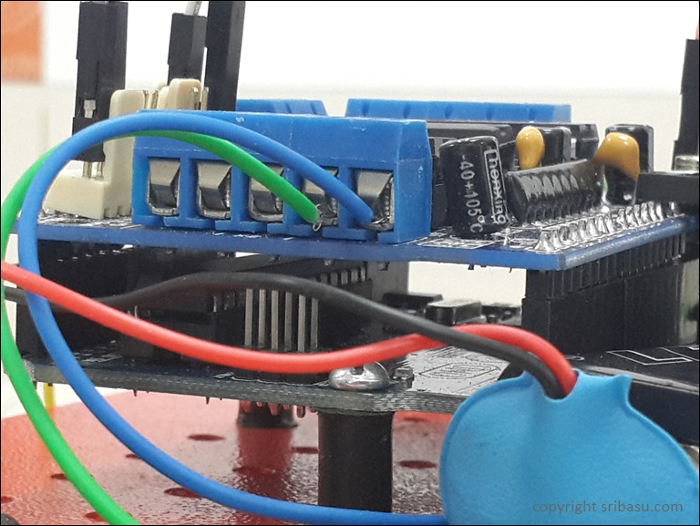
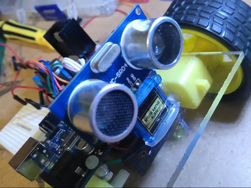
*Note: When mounting the Arduino board, leave enough space to plug the USB cable, since later you have to program the Arduino board by connecting it to the PC via a USB cable.
Nonetheless, the Arduino is a key part in making this entire project function and the placement of each module impacts its efficiency and aesthetics. The location of the distance sensor and Arduino need to be set in particular places, the Arduino will need to be screwed into the frame behind the battery pack holder, on the back end to balance the weight of this vehicle. Make sure to place the Arduino attachment on top of the Arduino for the motor functions to work correctly. Next, keep in mind that the distance sensor will need to be in front of this project to detect obstacles and scan other paths that are safer to proceed into.
Securing the Distance Sensor
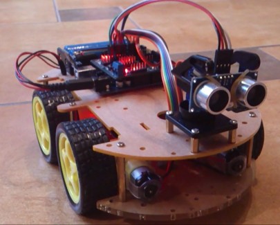
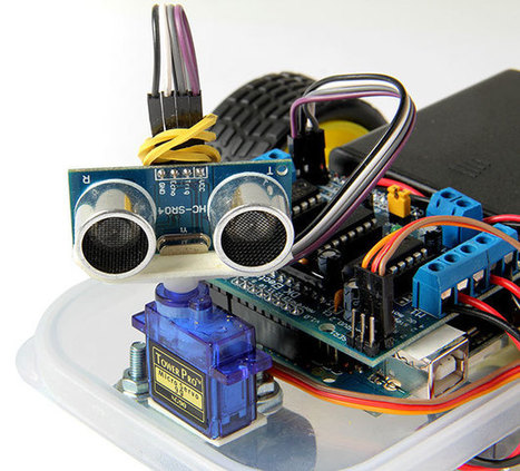
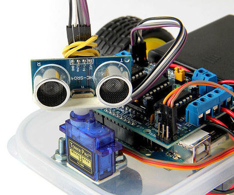
Not to mention, the distance sensor is a vital part in allowing this entire project to function and avoid obstacles in its path. For this step, you will need to connect two pieces of plastic that fit to secure the servo in place, attaching this to a plastic foundation to connect to our frame. This will provide the mechanism with mobility and rotation for any future movement that the distance sensor uses to move in any direction. Fasten this component into the front of the foundation or frame and now proceed to utilize the distance sensor.
With the distance sensor, you will need to attach this to the front of the mechanism you just created, by tape/glue/zip ties, so as the servo moves, the distance sensor does as well.
Plug four jumper wires to the Ultrasonic sensor and mount it on the mounting bracket. Then mount the bracket on the TowerPro micro servo which has already installed on the chassis.
Wire Connections & Circuit Schematic
.jpg)
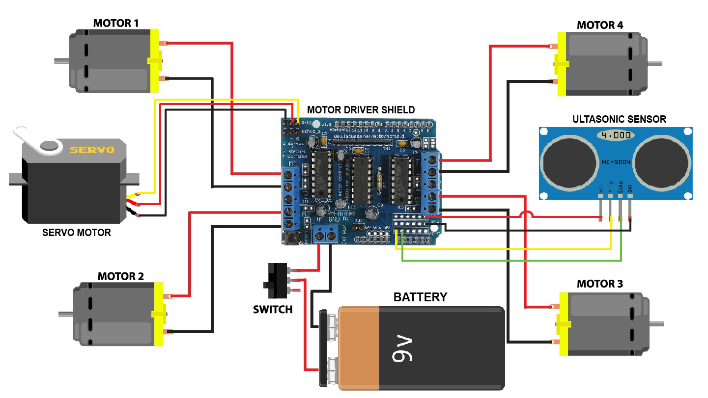
These wire connections are crucial in allowing the project to perform its functions, so make sure you double check what portion you are linking each component to. In the circuit schematic, you can find the necessary connections needed for the Arduino to drive, sense, etc.
*Note: This schematic involves four motors, however, we can ignore the extra two and proceed on.
The Code
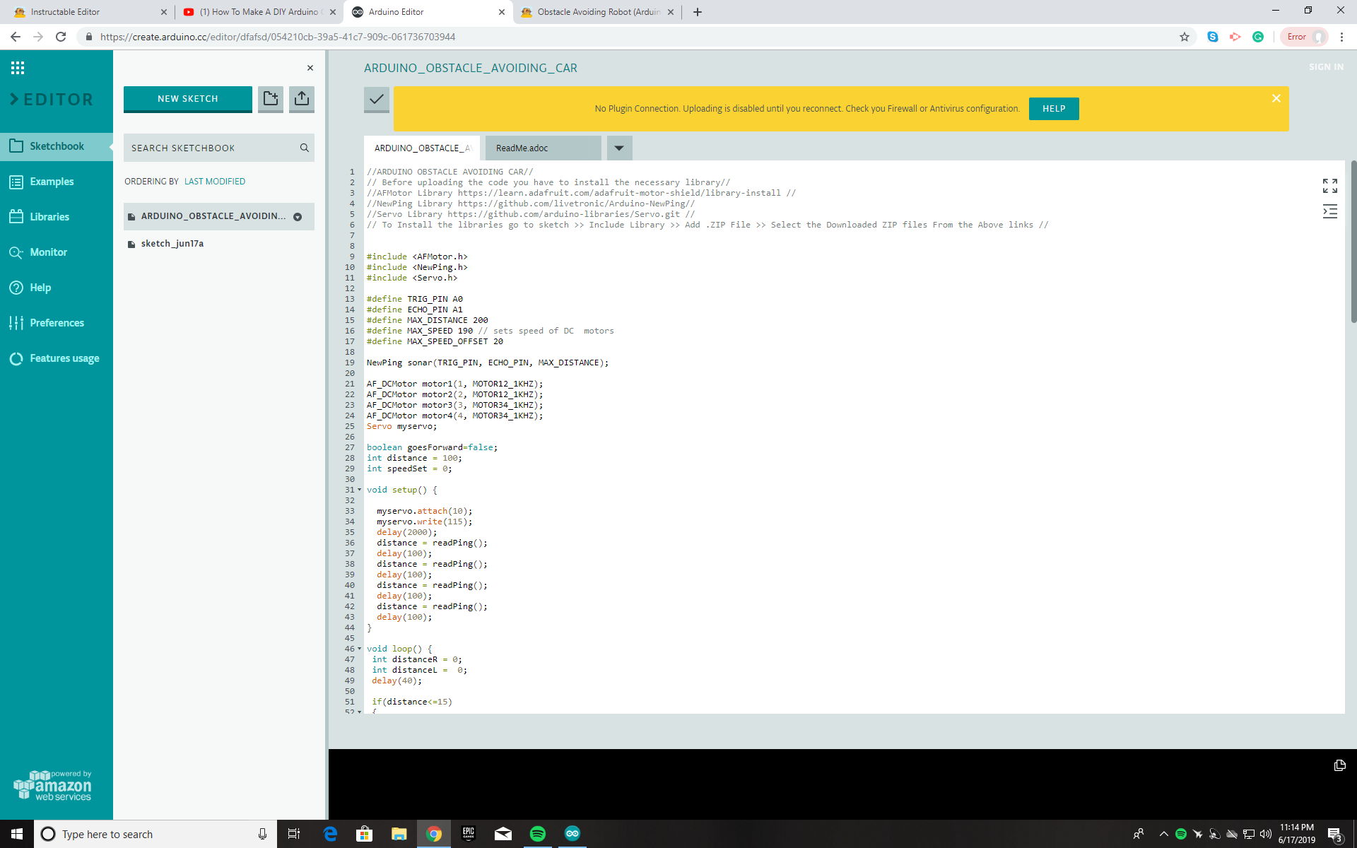
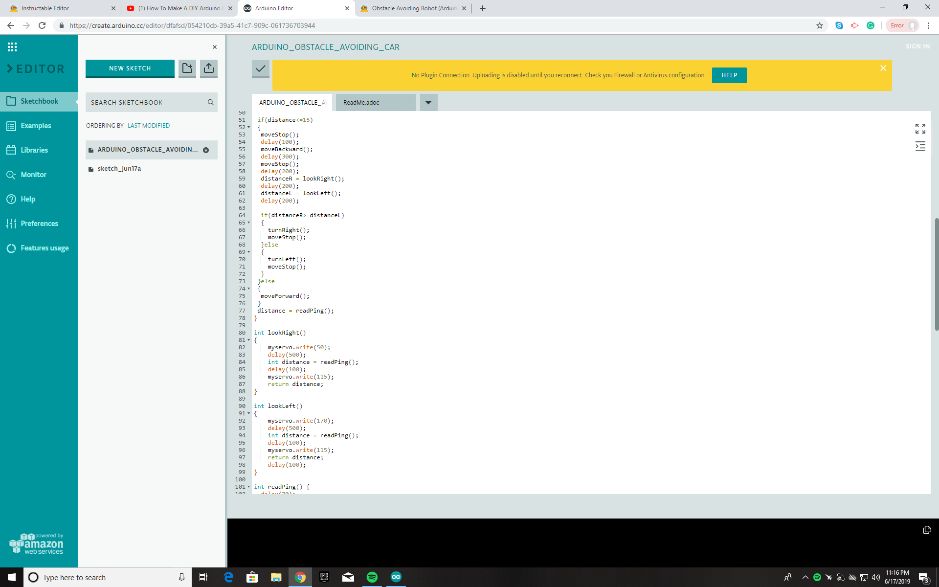
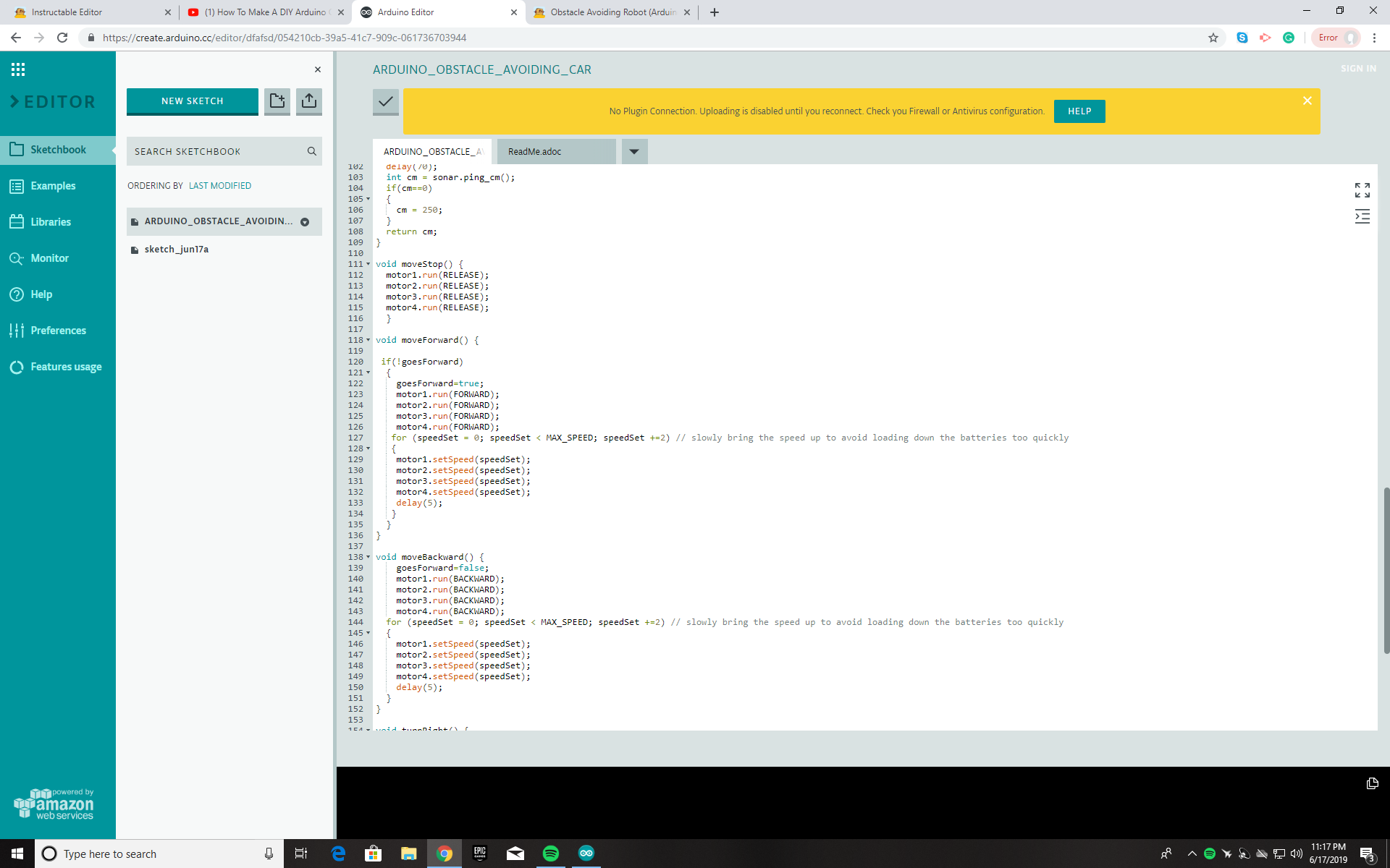
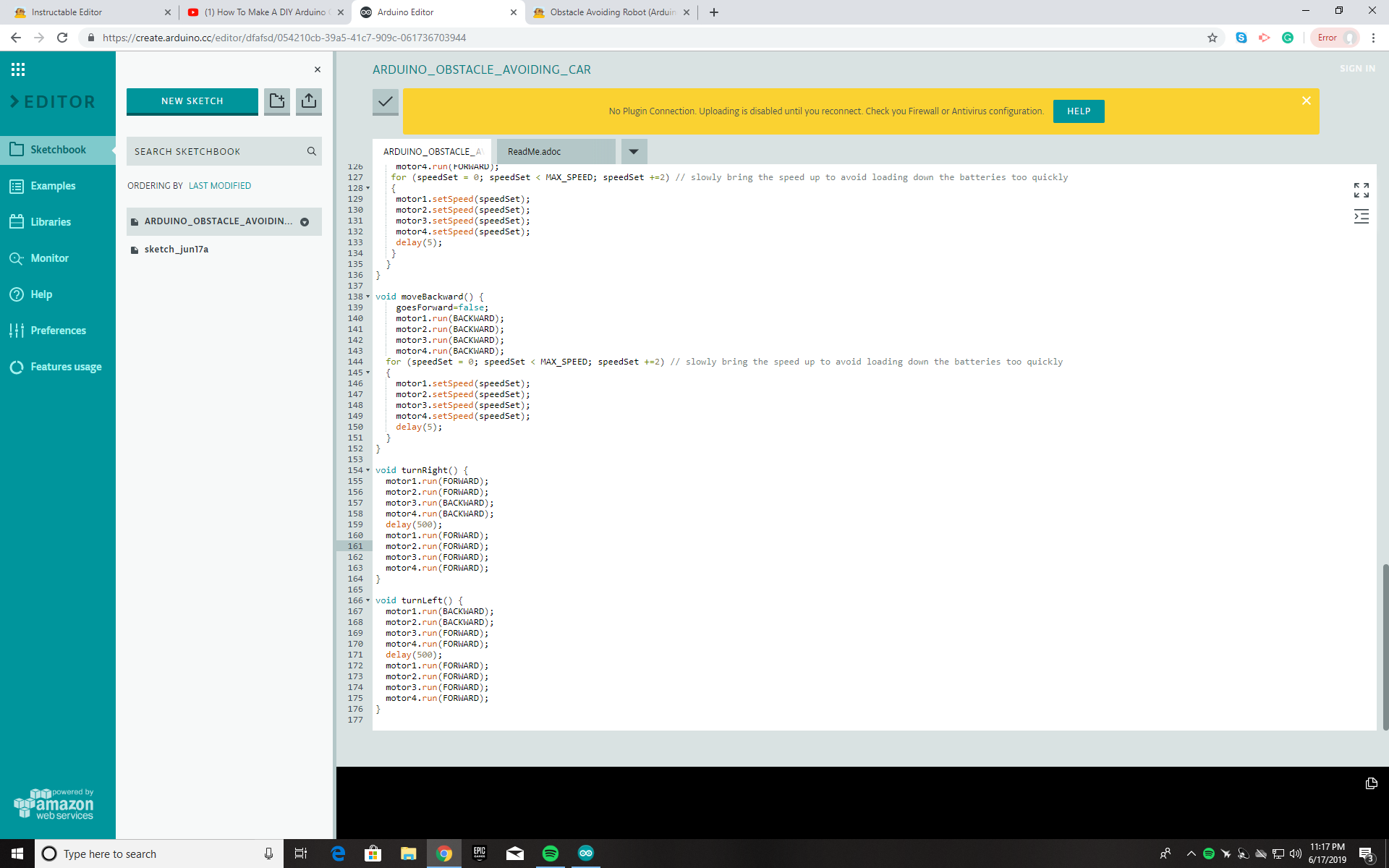
None of this will simply work without the code programmed within the Arduino. Here I have provided the code to function this entire project if wired and constructed correctly. You can take a look at the pictures provided to better understand and copy the code.
Finalization
.jpg)
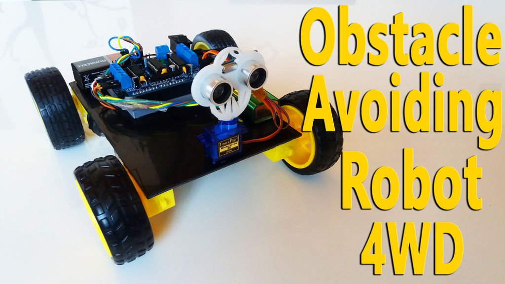
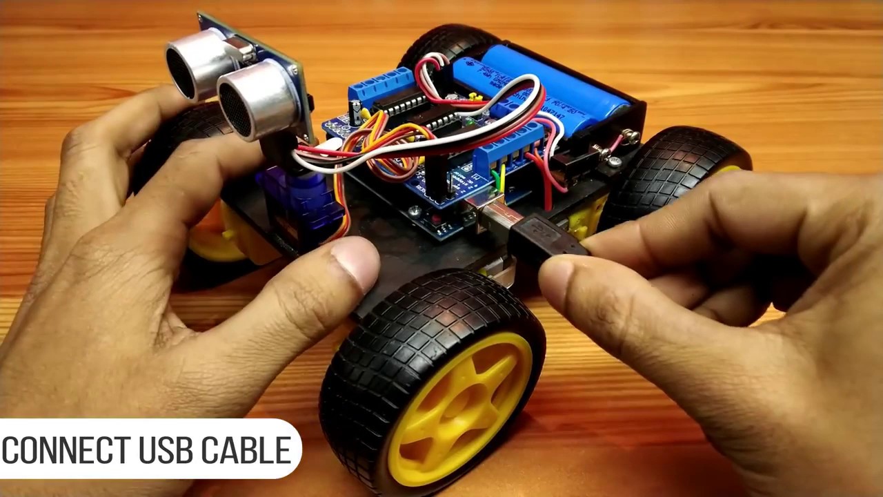
Due to the fact that we have completed all the steps, go over the process and clarify all connections/components that are incorporated within this project.
- Plug in your Arduino to your PC
- Download the Libraries needed(AFMOTOR, NEWPING)
- Compile the code
- Upload the code to the correct port
- Test, Unplug
- Click in the batteries, turn the switch on and let it drive!