Arduino OBD2 Simulator
.JPG)
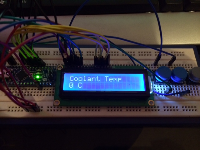
Ive been building an Arduino OBD2 Scanner to interface with my Jeep's OBD2 port, but it became a beeeeeg! schlep to upload code to my Arduino Nano + 16x2 LCD + ELM327 Scanner device, then haul the whole prototype to the Jeep in the gurage the whole time and then only to find there was something small i forgot to change.
I needed to find a way to test my prototype in the comfort of my home.
Ive searched high and low and couldn't find any Arduino OBD2 simulators that i can build my self. I came across one or two websites that's making use of Arduino to build an OBD2 Simulator but they dont give you the code you have to buy the ready made product from them, I.E the FreeMatics for something like a whopping $169, Wheres the love for Open source in that ???? pffft! I dont see $169 I see about 8 Arduinos i can buy with it.
So unfortunatly and fortunatly for you :-) I had to figure out how i'm going to build one my self, which forced me to now focus on a project i had to take on in order to complete my initial project, Took me some time to figure out how to send PIDs in standard OBD2 format. But at the end i could connect a FreeObd Scanner program which you normally get with your ELM327 Scanner.
Stuff you need.
Arduino UNO
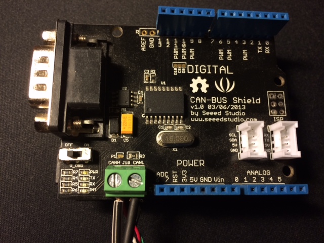
CAN-BUS Shield
ELM327 (USB,Bluetooth,Wifi) It doesnt matter which flavour you have. As long as it creates a com port
OBD2 Diagnostics software (Just to Test if it works) any OBD2 software should work, the software you got with the ELM327 scanner should do just fine.
Step 1: the Code
Unfortunately for this to work you MUST have a Shield from SeeedStudio Called the CAN-BUS Shield. You also get one from Skpang but the code below will not work for Skpang unless you alter it slightly.
If you dont know already you also need the SeeedStudion CAN-BUS Library loaded int he Arduino IDE.
Upload the below code, if you dont have the CAN-BUS Shield library loaded the below will most probably error out.
//This Arduino UNO Sketch requires the Seeed CAN-BUS Shield Libraries
//https://github.com/yexiaobo-seeedstudio/CAN_BUS_Shield
#include
#include "mcp_can.h"
INT32U canId = 0x000;
//2024 4 65 12 18 248 185 147
unsigned char len = 0;
unsigned char buf[8];
char str[20];
String BuildMessage="";
int MSGIdentifier=0;
void setup()
{
    Serial.begin(38400);
START_INIT:
    if(CAN_OK == CAN.begin(CAN_500KBPS))
    {
        Serial.println("CAN BUS Shield init ok!");
    }
    else
    {
        Serial.println("CAN BUS Shield init fail");
        Serial.println("Init CAN BUS Shield again");
        delay(100);
        goto START_INIT;
    }
}
void loop()
{
char rndCoolantTemp=random(1,200);
char rndRPM=random(1,55);
char rndSpeed=random(0,255);
char rndIAT=random(0,255);
char rndMAF=random(0,255);
char rndAmbientAirTemp=random(0,200);
char rndCAT1Temp=random(1,55);
//GENERAL ROUTINE
unsigned char SupportedPID[8] = {1,2,3,4,5,6,7,8};
unsigned char MilCleared[7] = {4, 65, 63, 34, 224, 185, 147};
//SENSORS
unsigned char CoolantTemp[7] = {4, 65, 5, rndCoolantTemp, 0, 185, 147};
unsigned char rpm[7] = {4, 65, 12, rndRPM, 224, 185, 147};
unsigned char vspeed[7] = {4, 65, 13, rndSpeed, 224, 185, 147};
unsigned char IATSensor[7] = {4, 65, 15, rndIAT, 0, 185, 147};
unsigned char MAFSensor[7] = {4, 65, 16, rndMAF, 0, 185, 147};
unsigned char AmbientAirTemp[7] = {4, 65, 70, rndAmbientAirTemp, 0, 185, 147};
unsigned char CAT1Temp[7] = {4, 65, 60, rndCAT1Temp, 224, 185, 147};
unsigned char CAT2Temp[7] = {4, 65, 61, rndCAT1Temp, 224, 185, 147};
unsigned char CAT3Temp[7] = {4, 65, 62, rndCAT1Temp, 224, 185, 147};
unsigned char CAT4Temp[7] = {4, 65, 63, rndCAT1Temp, 224, 185, 147};
if(CAN_MSGAVAIL == CAN.checkReceive())
{
CAN.readMsgBuf(&len, buf);
canId = CAN.getCanId();
Serial.print("<");Serial.print(canId);Serial.print(",");for(int i = 0; i
BuildMessage="";
    }

}
Step 2: Preparing the ELM327 Scanner Cable to Test Your New OBDII Simulator.
.JPG)
.JPG)
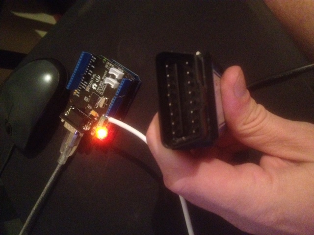
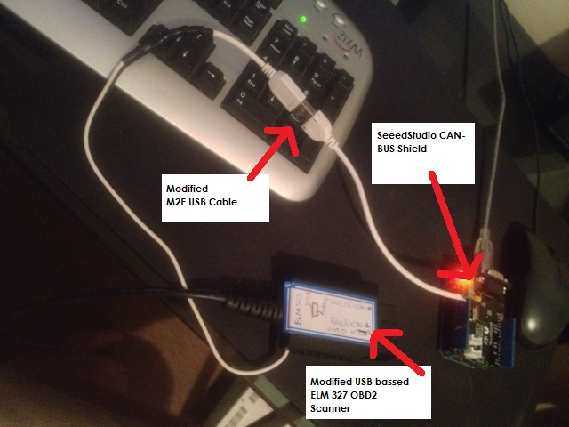
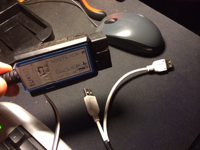
You can do it which ever way you like. since the ELM327 Scanner cable is quite cheap i modified it to my liking.
I removed the original sticker to get to the 4 screws to open the box, I took a male to female extender USB cable and cut it in half.
and soldered the one piece of the USB cable's end to pin 6-CAN High and Pin 14-CAN Low, made a little hole on the side, closed it up and stuck a sticker on the side to remind me which is which. Look at the photo's
I then terminated the other half of the USB extender cable to the SeeedStudio Can-BUS shield, Obviously CAN-H from ELM327 to CAN-H on the Shield and same with the CAN-L wires.
Step 3: the Testing.
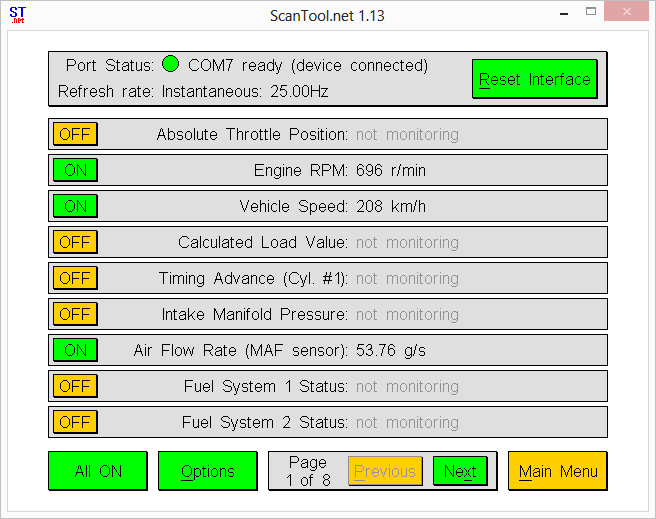
I then powered up the Arduino, The Arduino+CANBUS Shield is now stand alone and doesnt need a pc but i just left it connected to get power from the USB port.
Then connectr the ELM327 to USB, in the device manager make sure which comport belongs to the ELM327 double check because you now have 2 com ports the Arduino's COM Port and the ELM327.
Start an OBD diagnostics windows program I.E ScanTool.net then let it monitor the RPM.
The OBD Simulator isnt smooth because its programmed to randomly generate "Valid" data I.E the RPM wil randomly jump from say 5RPM to 800RPM to 20RPM to 1800RPM ect ect, Ive made notes in the Arduino code, its easily readable and doesnt support all PID data but you can certainly add to it. By looking at some of the standard PIDs from Wiki and following "My" methodology
http://en.wikipedia.org/wiki/OBD-II_PIDs
You can also if you want build it into a box then add a few buttons to alter the variables assigned to the random generator function, I didnt need smooth values, Just as long as i'm able to test my Arduino ScanTool Prototype.