Arduino Nano: Read Multiple DS1820/DS18S20 Maxim One Wire Thermometers With Visuino
by BoianM in Circuits > Arduino
10420 Views, 30 Favorites, 0 Comments
Arduino Nano: Read Multiple DS1820/DS18S20 Maxim One Wire Thermometers With Visuino
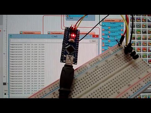
One of the reasons the OneWire Maxim DS1820/DS18S20//DS18B20 Thermometers are so popular is that multiple thermometers can be connected and even powered by only 2 wires. I already posted Instructables on how to connect one Thermometer, and how to get the Address of a Thermometer. In this Instructable, I will show you how you can connect multiple Thermometers to a single Arduino pin, and read their temperature, with the help of Visuino.
Components
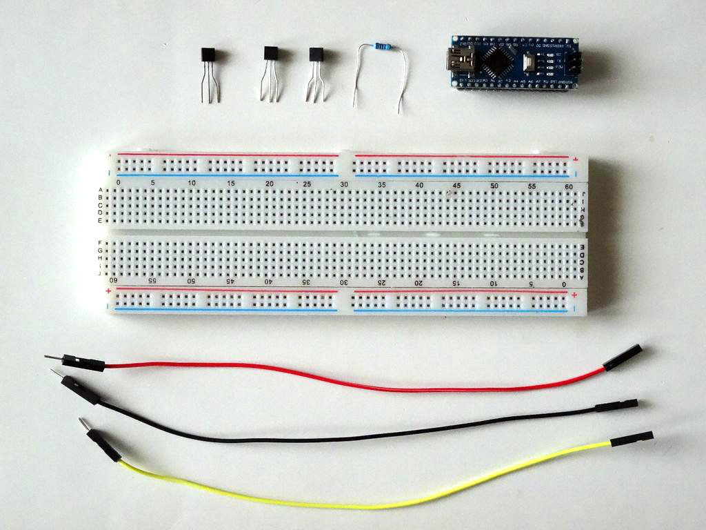
- One Arduino compatible board (I use Arduino Nano, because I have one, but any other will be just fine )
- Multiple DS18S20 Thermometers (I used 3 for this Instructable)
- One 4.7 K Resistor
- One Breadboard
- 3 Male-Female jumper wires
Install the Thermometers on the Breadoard, and Add Pull-Up Resistor
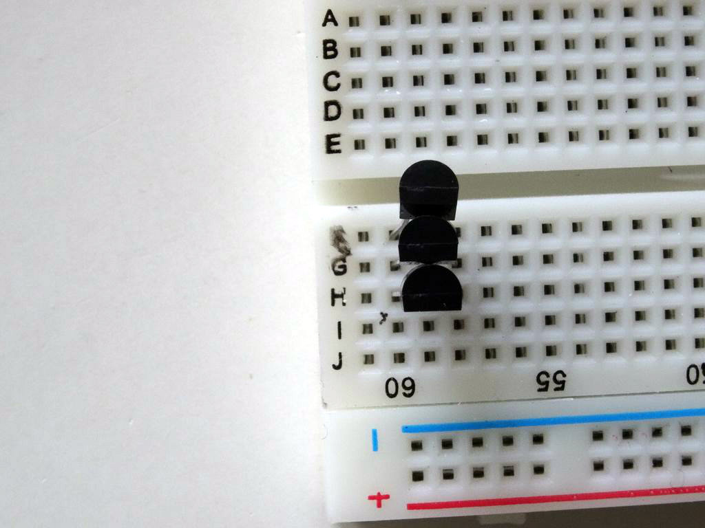
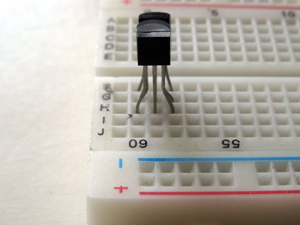
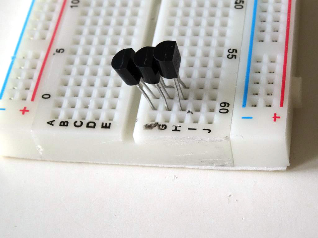
- Place the Thermometers on the Breadboard as shown on Pictures 1, 2, and 3
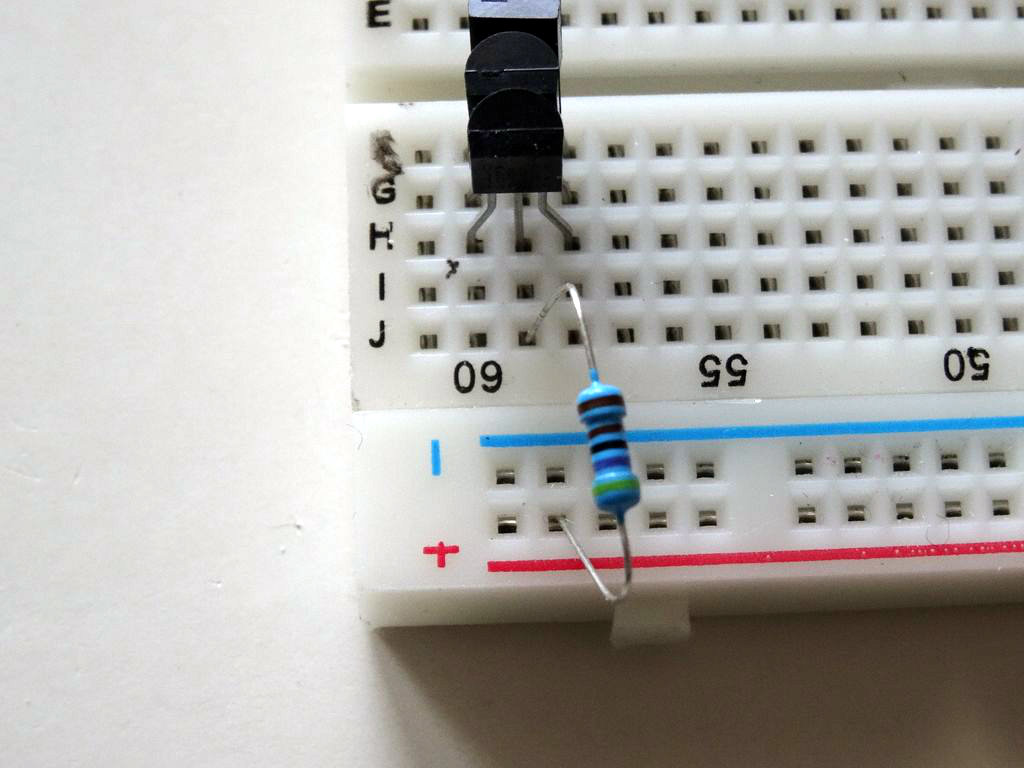
- Connect the 4.7 K Resistor between the middle pin of the Thermometers and the Power bus of the Breadboard (Picture 4)
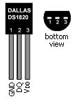
- Picture 5 shows the pins on the DS18S20 Thermometer. The VDD pin is optional, and in our case we will not connect it.
Connect Power and Data Wires for the Thermometers
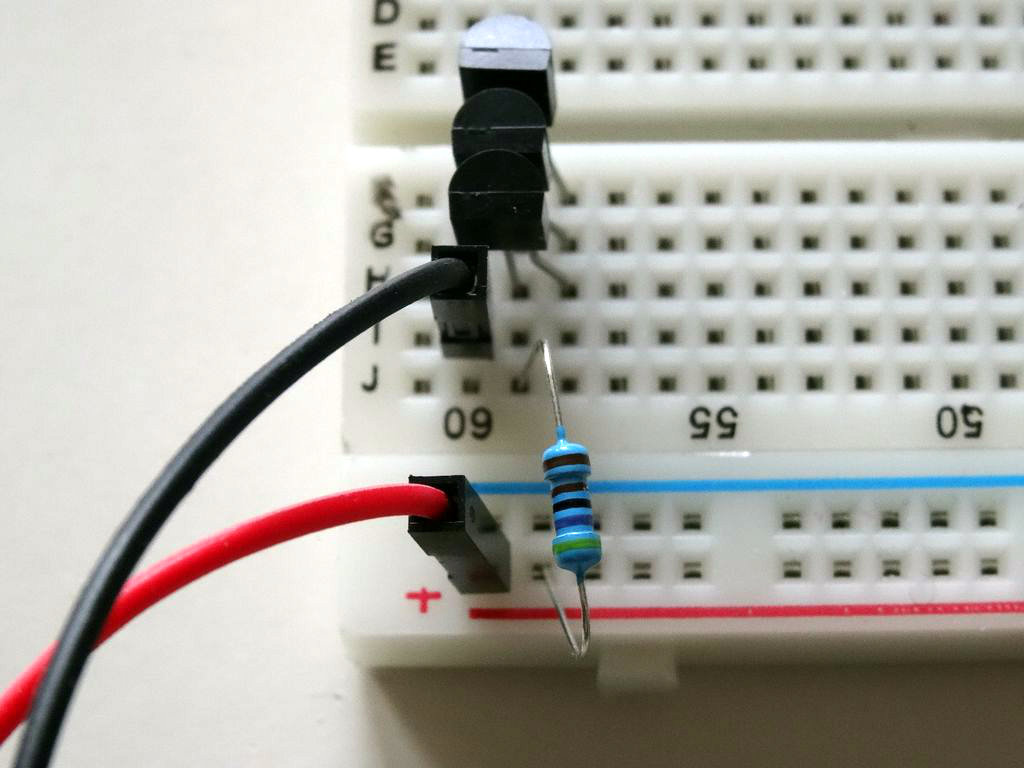
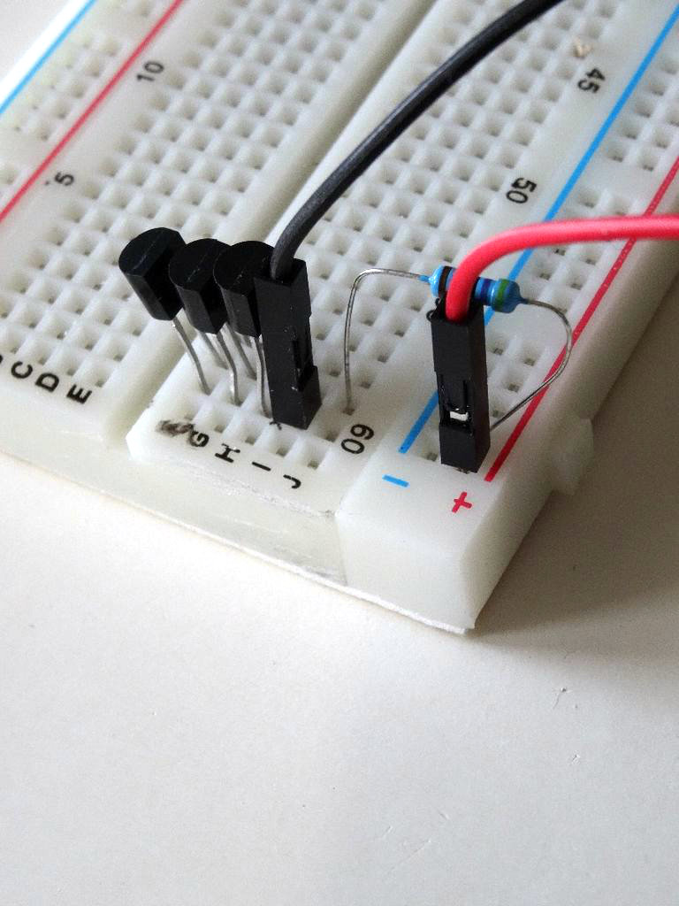
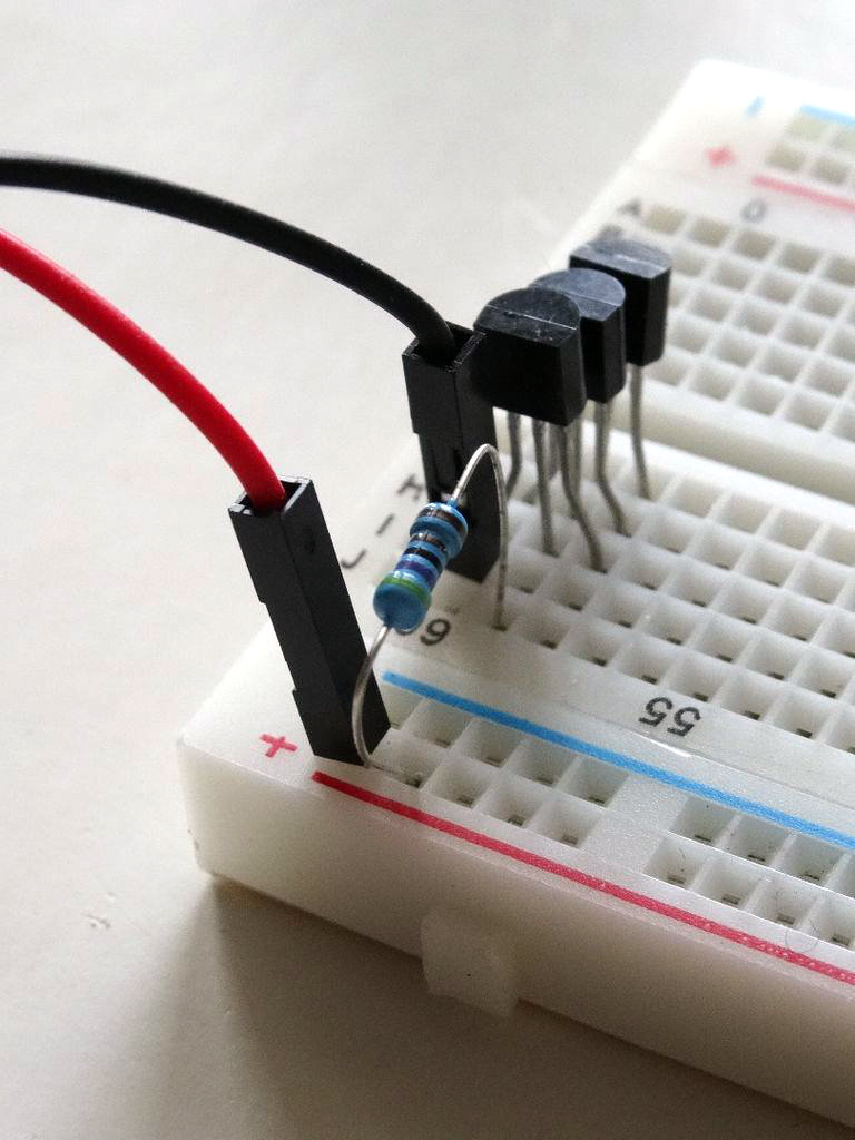
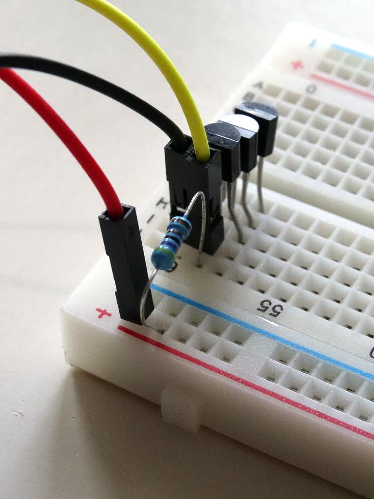
- Connect a jumper wire(Black wire) for Ground to the first (Ground) pin of the Thermometers (Pictures 1, 2 and 3)
- Connect jumper wire(Red wire) for Power to the Power bus of the Breadboard (Pictures 1, 2 and 3)
- Connect jumper wire(Yellow wire) for Data to the middle pin of the Thermometer where the Resistor was connected in the previous step(Picture 4)
Connect the Thermometers to Arduino
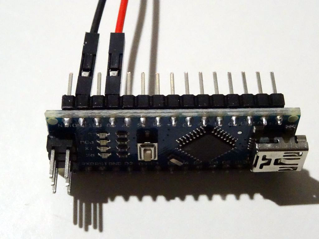
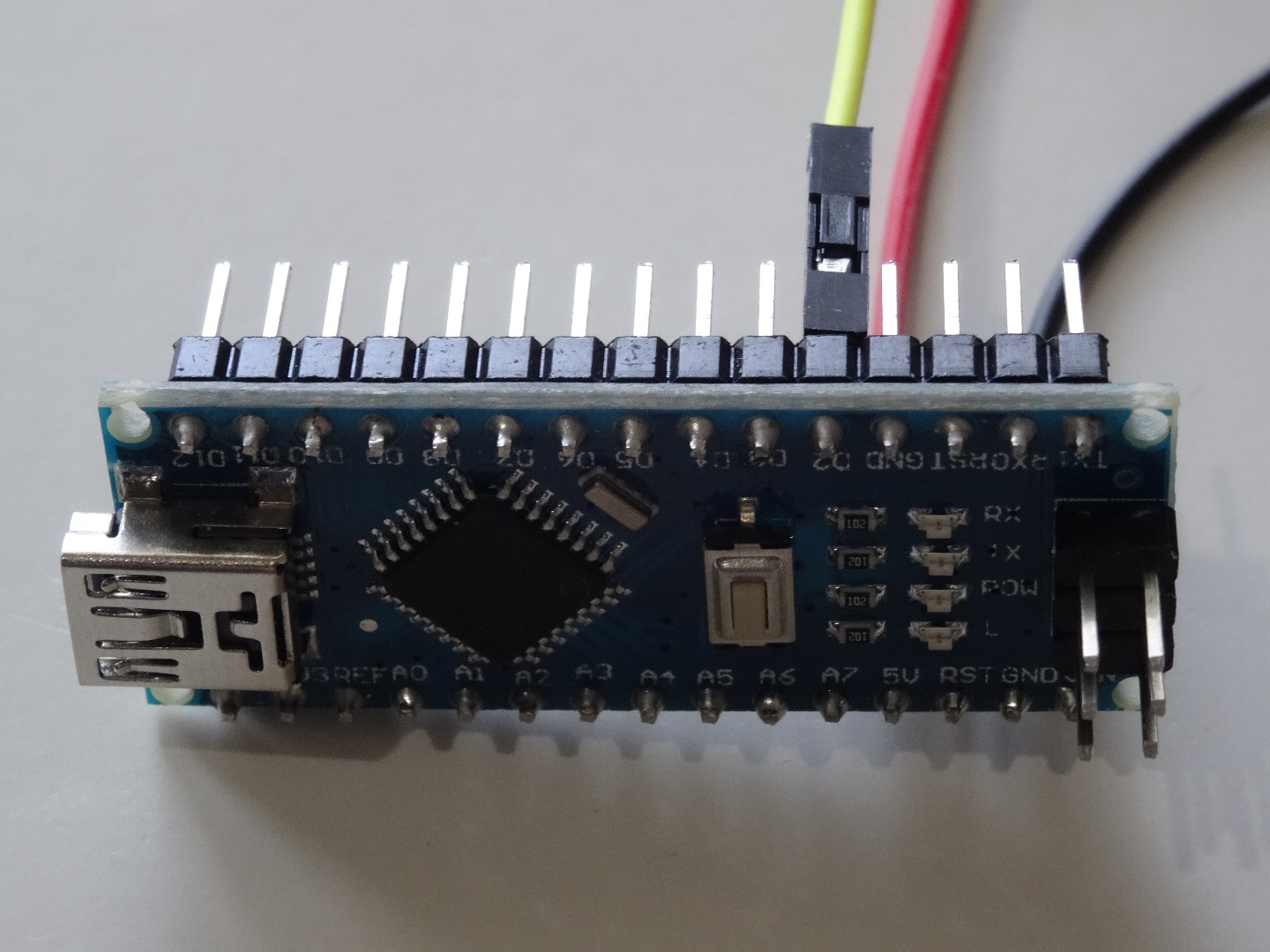
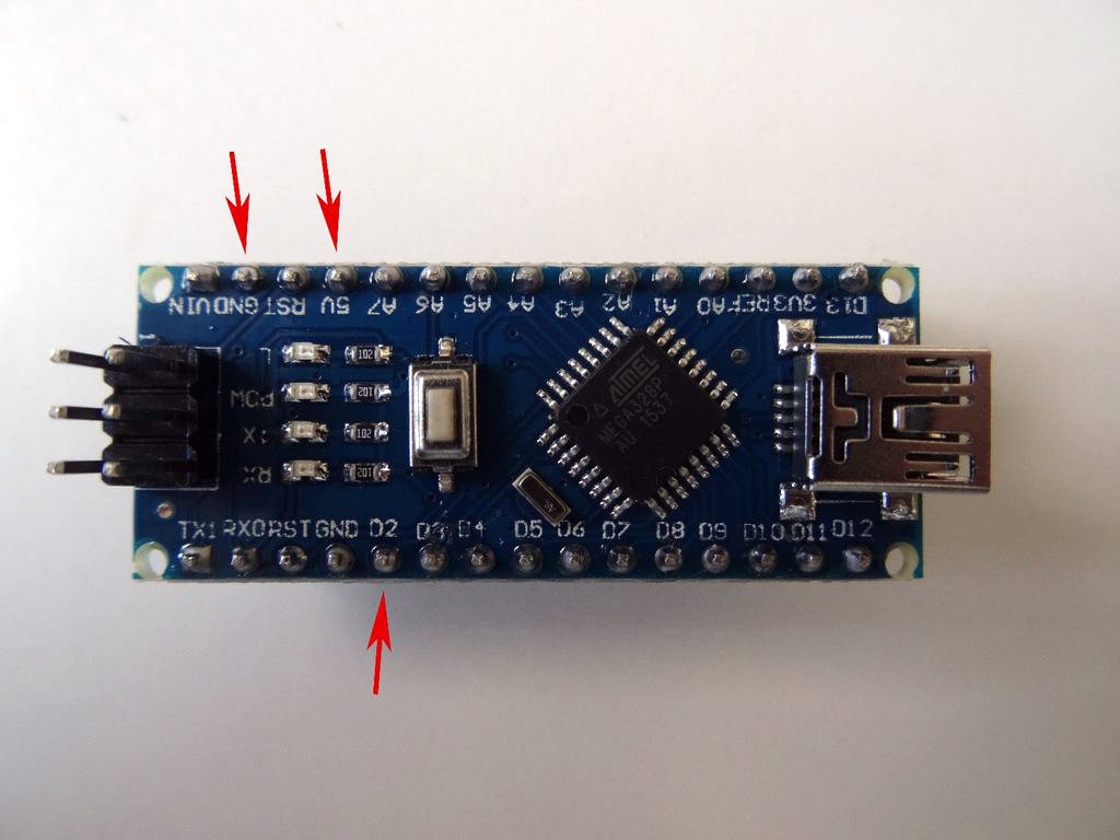
- Connect the other end of the Ground wire(Black wire) to Ground pin of the Arduino board(Picture 1)
- Connect the other end of the Power wire(Red wire) to the 5V power pin of the Arduino board(Picture 1)
- Connect the other end of the Data wire(Yellow wire) to Digital pin 2 of the Arduino board(Picture 2)
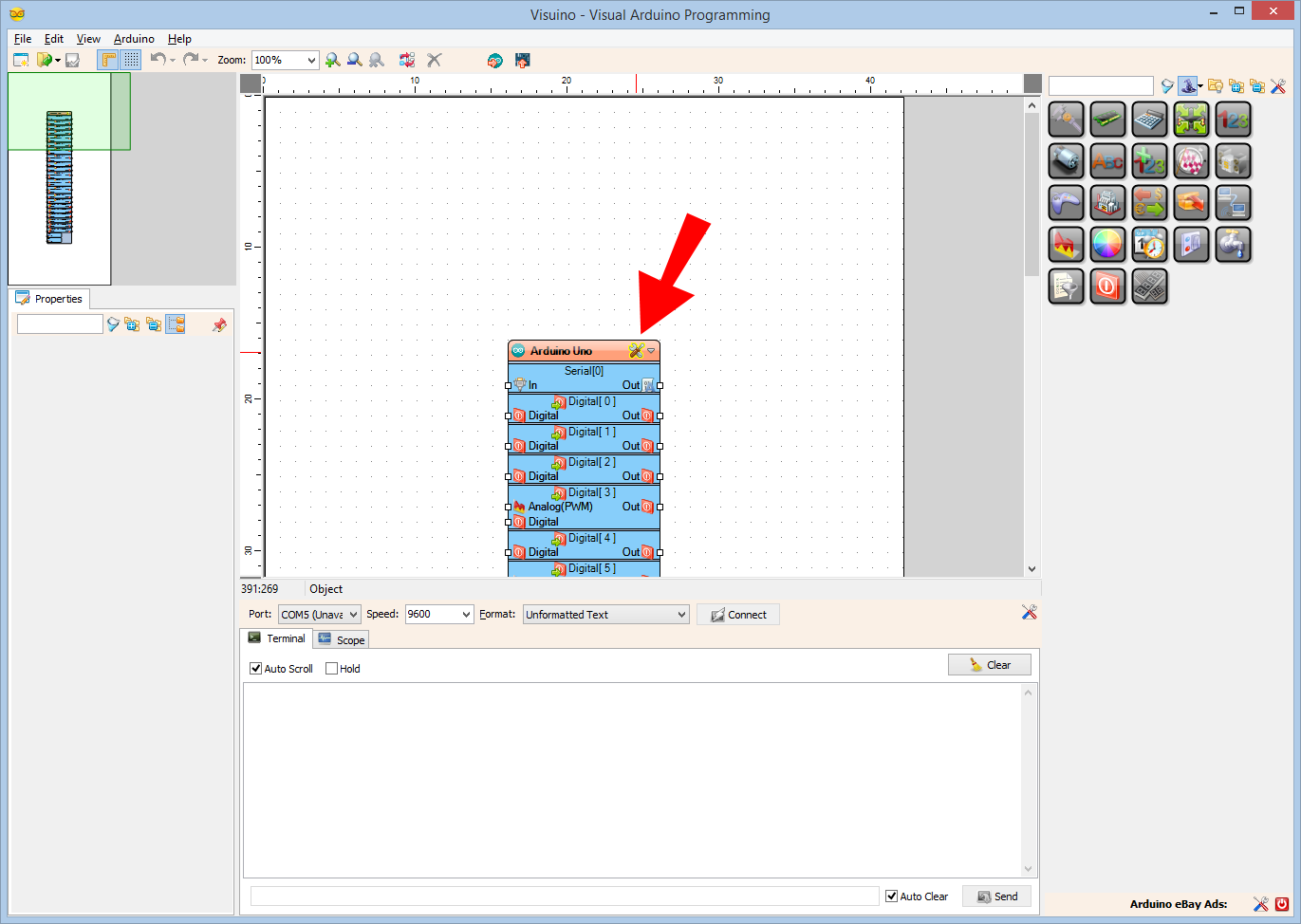
- Picture 3 shows where are the Ground, 5V Power, and Digital 2 pins of the Arduino Nano
Start Visuino, and Select the Arduino Board Type
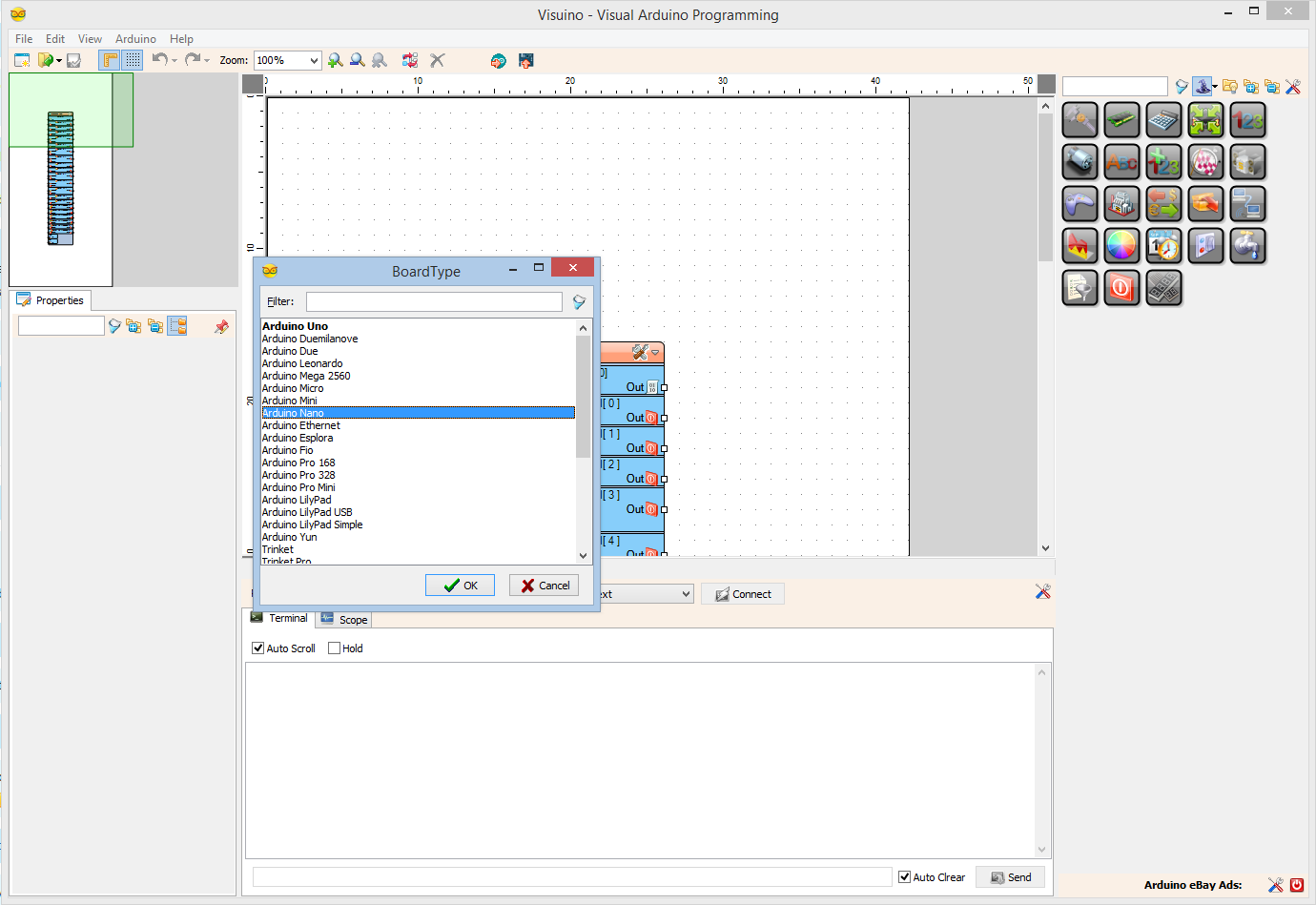
To start programming the Arduino, you will need to have the Arduino IDE installed from here: http://www.arduino.cc/ .
Please be aware that there are some critical bugs in Arduino IDE 1.6.6.
Make sure that you install 1.6.7 or higher, otherwise this Instructable will not work!
The Visuino: https://www.visuino.com also needs to be installed.
In Visuino: Add OneWire Thermometer Components, and Connect Them
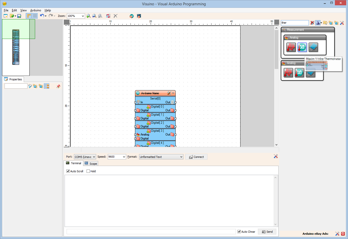
- Type "ther" in the Filter box of the Component Toolbox then select the "Maxim 1-Wire Thermometer" component (Picture 1), and drop 3 of them in the design area (If you use different number of Thermometers than 3 add one component for each)
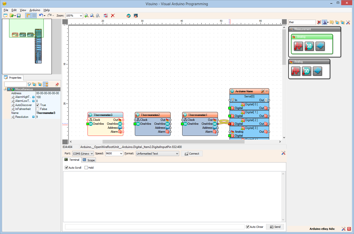
- Connect the "OneWire" output pin of the Thermometer1 component to the "Digital" input pin of the Digital[ 2 ] channel of the Arduino component(Picture 2)
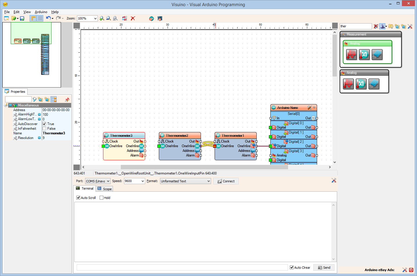
- Connect the "OneWire" output pin of the Thermometer2 component to the "OneWire" input pin of the Thermometer1(Picture 3)
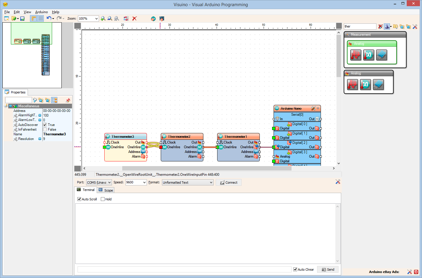
- Connect the "OneWire" output pin of the Thermometer3 component to the "OneWire" input pin of the Thermometer2(Picture 4)
- If you have more components continue to connect the "OneWire" outputs to the "OneWire" inputs
In Visuino: Add Formatted Text Component and Elements in It
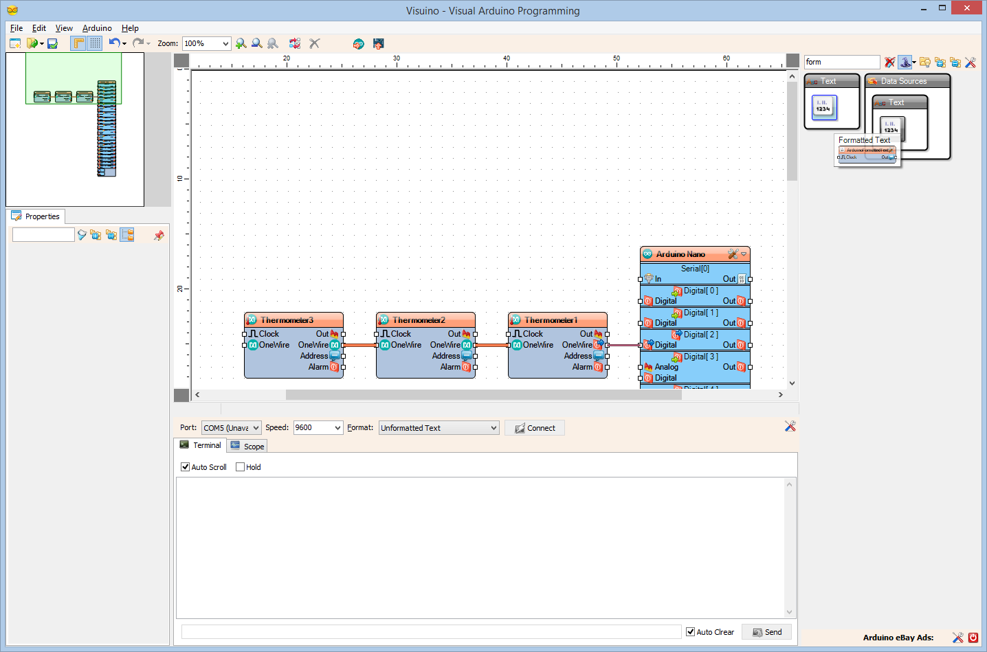
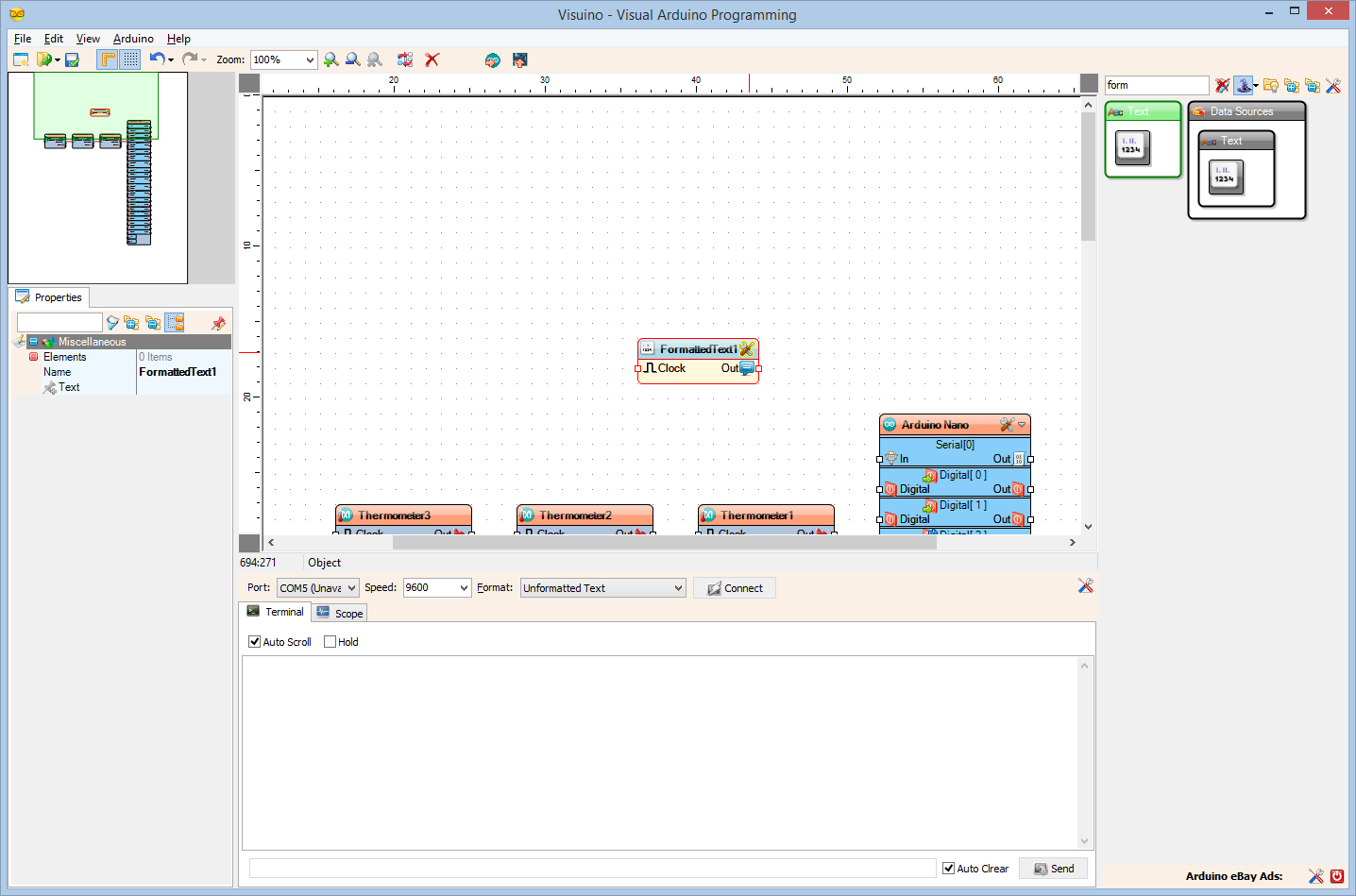
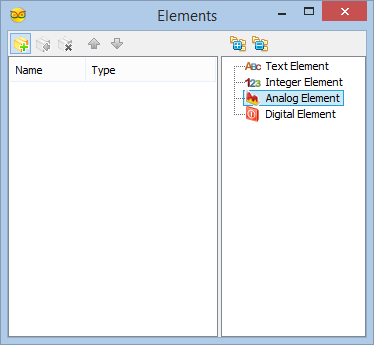
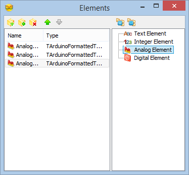
To display the Temperatures in the Serial Terminal, we will use Formatted Text component. This component allows you to generate customized formatted text from multiple data values.
- Type "form" in the Filter box of the Component Toolbox then select the "Formatted Text" component (Picture 1), and drop it in the design area
- Click on the "Tools" button of the FormattedText1 component (Picture 2)
- In the Elements editor, select the "Analog Element" from the list, and click 3 times(once for each Thermometer) on the "+" button(Picture 3) to add 3 elements (Picture 4)
- Close the Elements editor
In Visuino: Connect the Formatted Text Component, and Specify Formatted Text
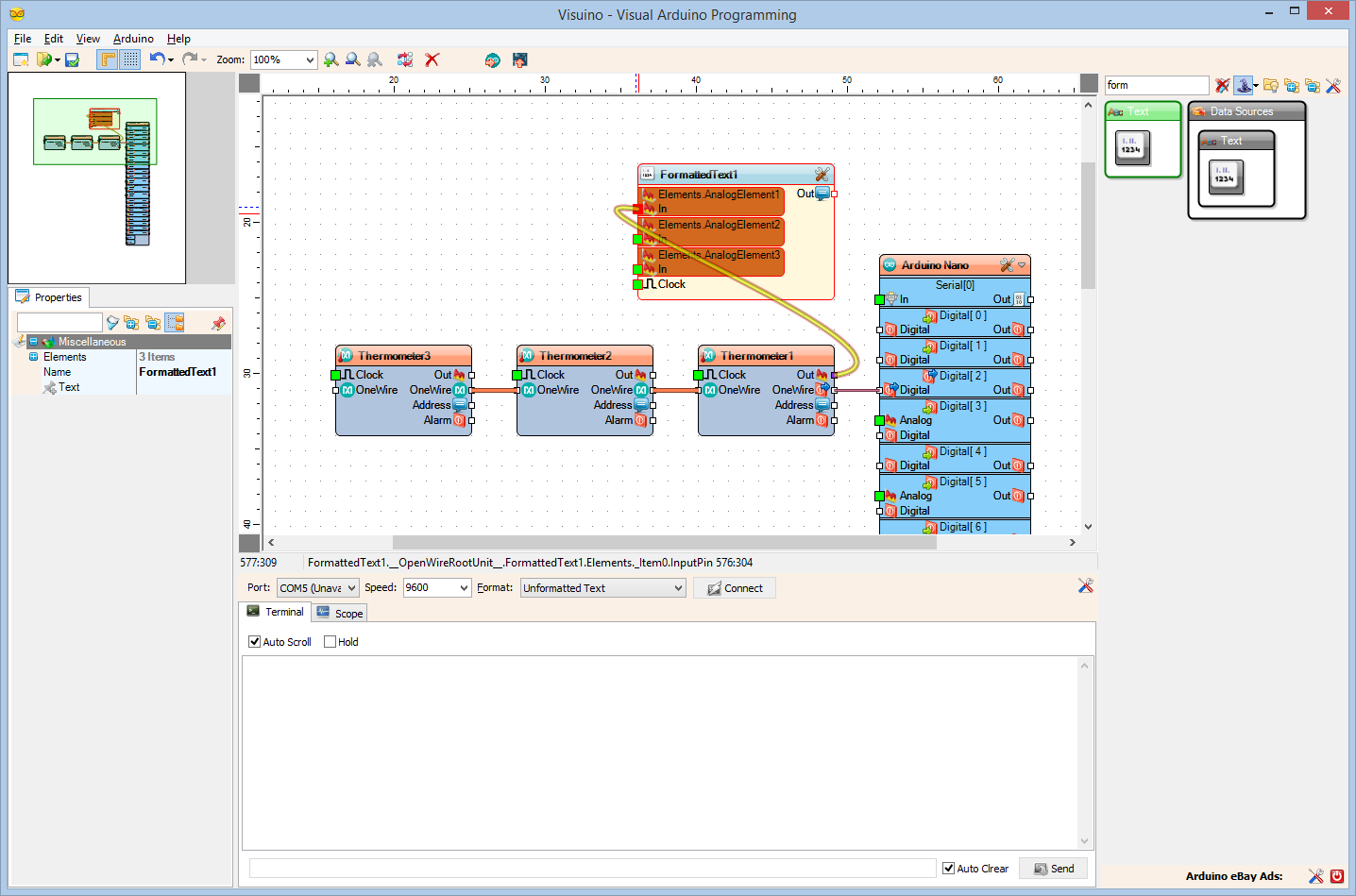
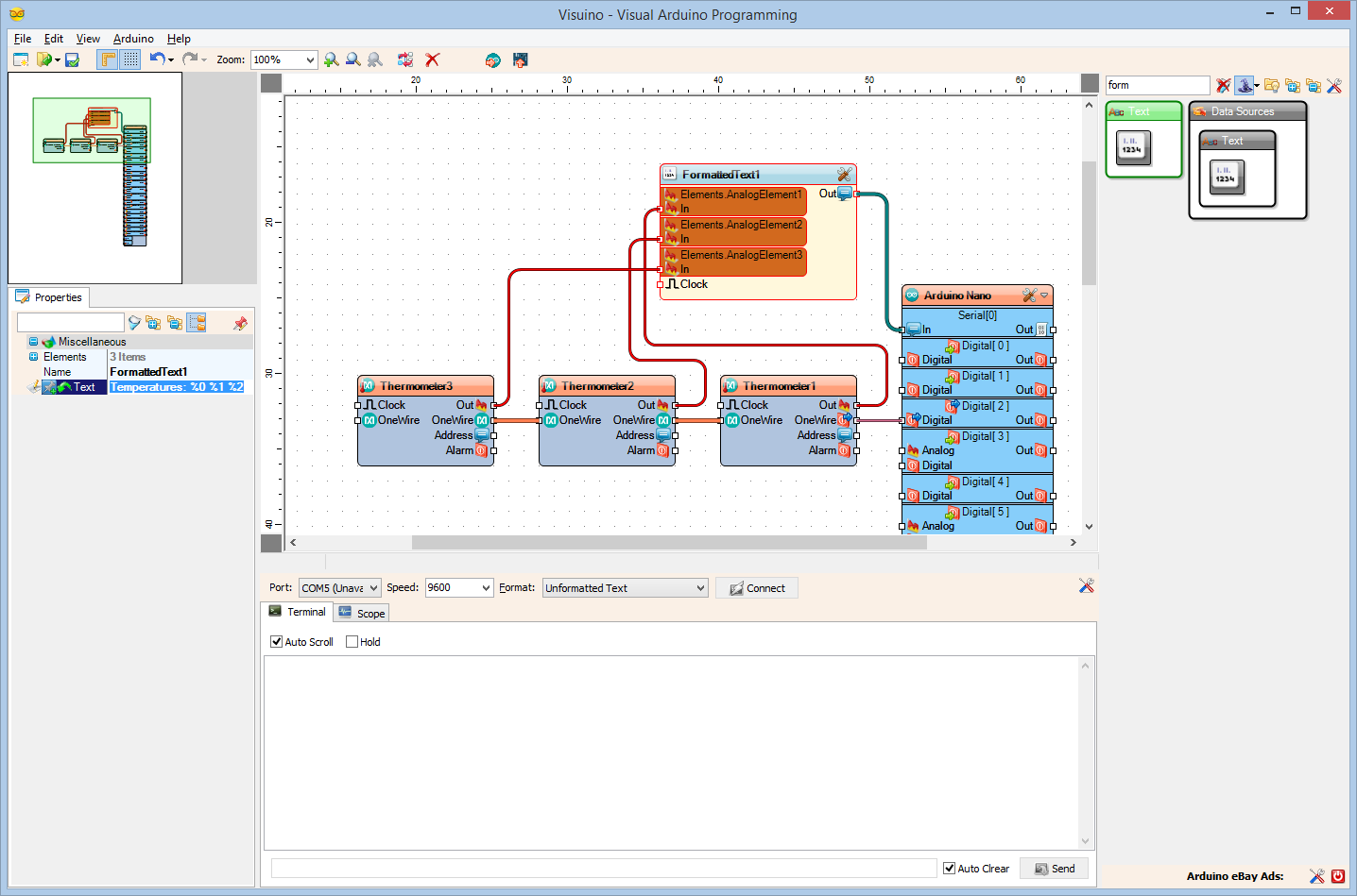
- Connect the "Out" pin of the Thermometer1 component to the In pin of the AnalogElement1 of the FormattedText1 component (Picture 1)
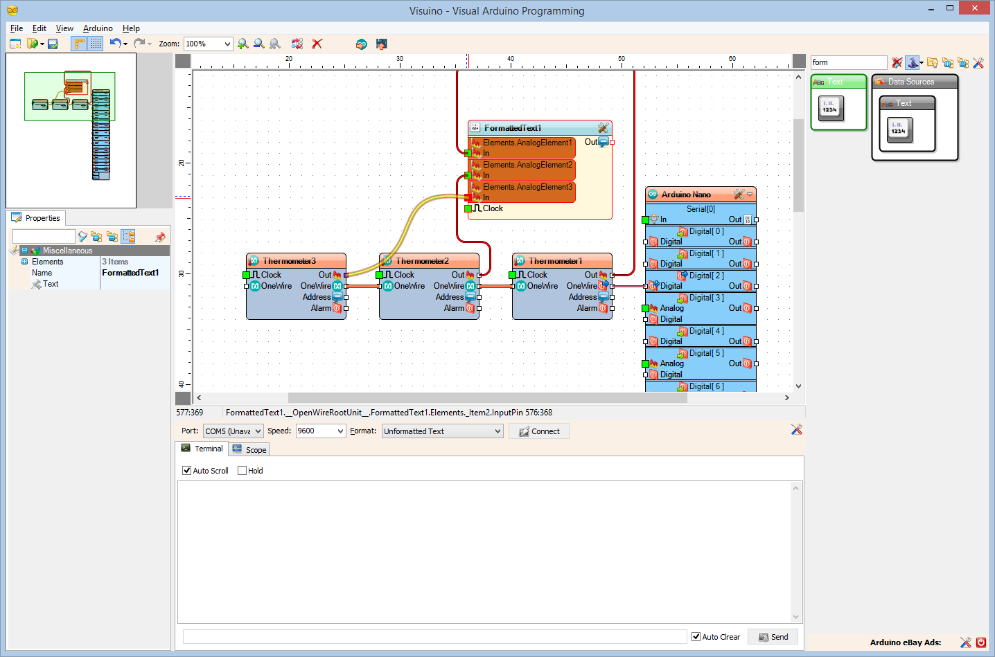
- Connect the "Out" pin of the Thermometer2 component to the In pin of the AnalogElement2 of the FormattedText1 component (Picture 2)
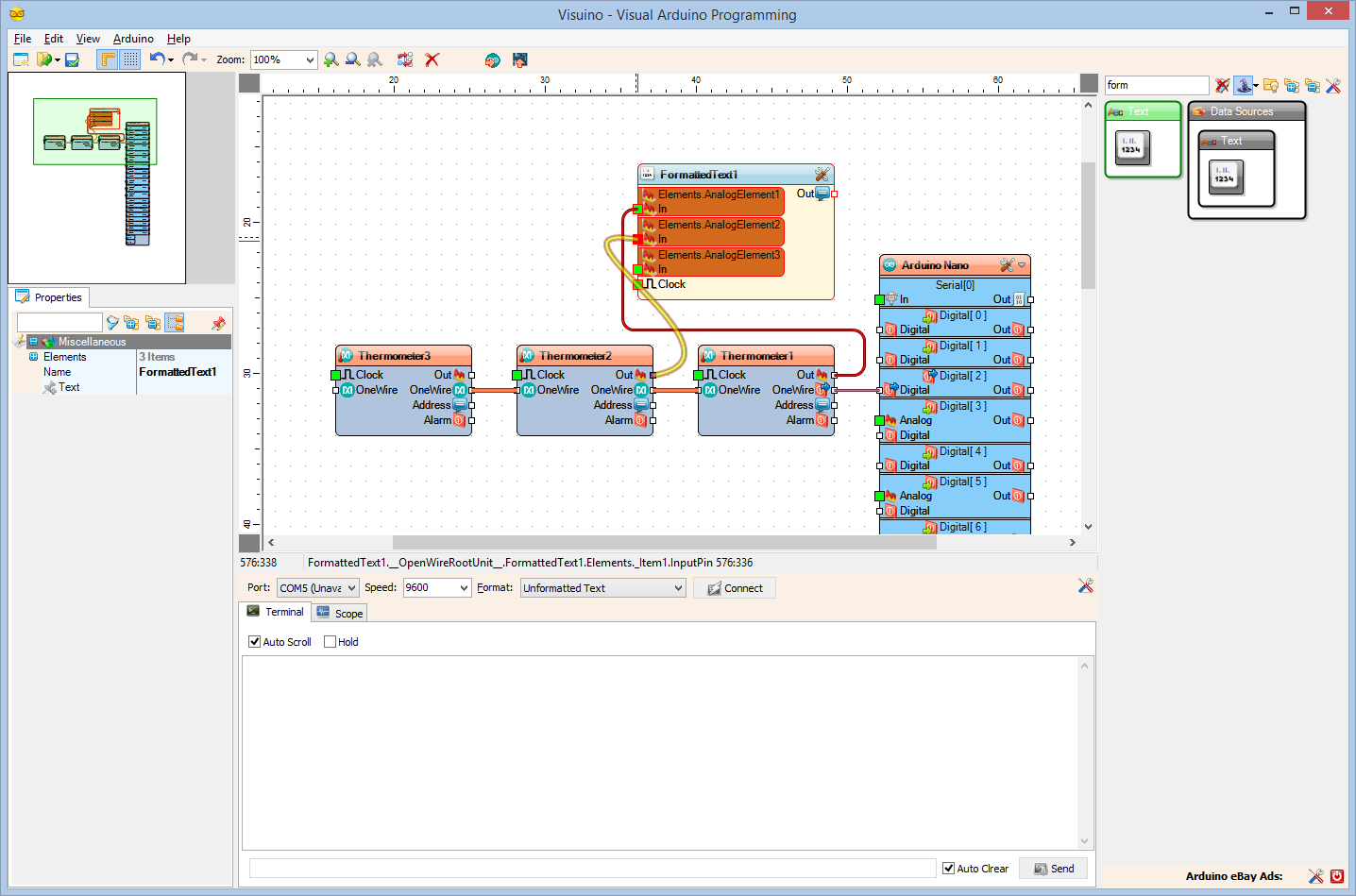
- Connect the "Out" pin of the Thermometer3 component to the In pin of the AnalogElement3 of the FormattedText1 component (Picture 3)
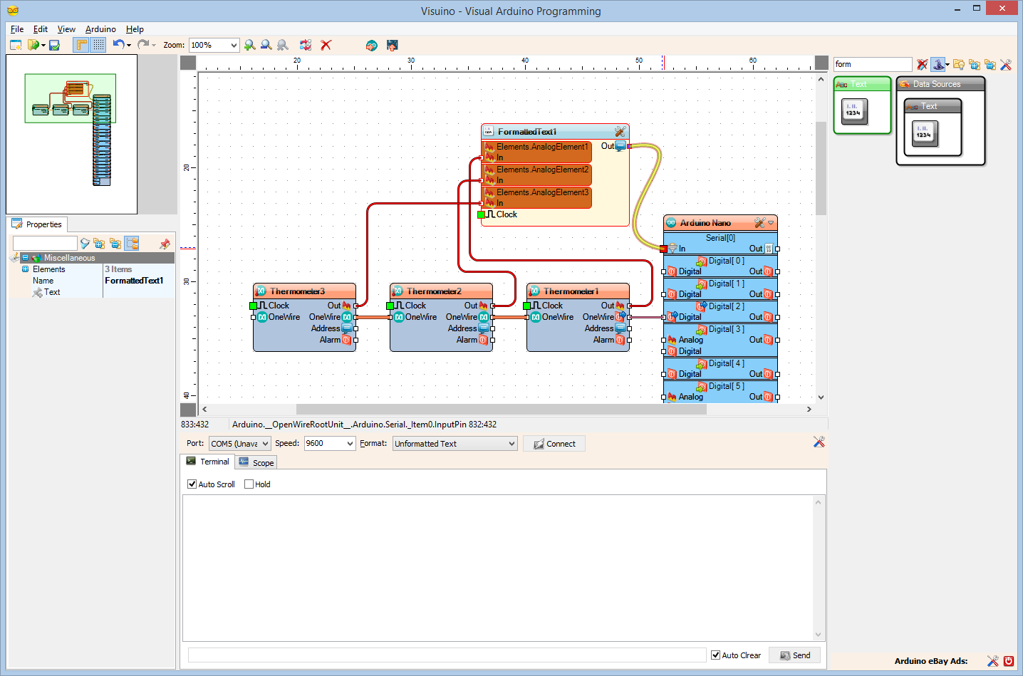
- Connect the "Out" output pin of the FormattedText1 component to the "In" input pin of the Serial[ 0 ] channel of the Arduino component(Picture 4)
- In the Object Inspector set the value of the Text property of the FormattedText1 component to "Temperatures: %0 %1 %2" (Picture 5). The %0 will be replaced with the value from AnalogElement1, %1 will be replaced with the value from AnalogElement2, and %2 will be replaced with the value from AnalogElement3
In Visuino: Optionally Set the Thermometer Address
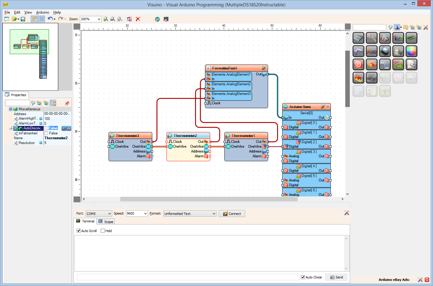
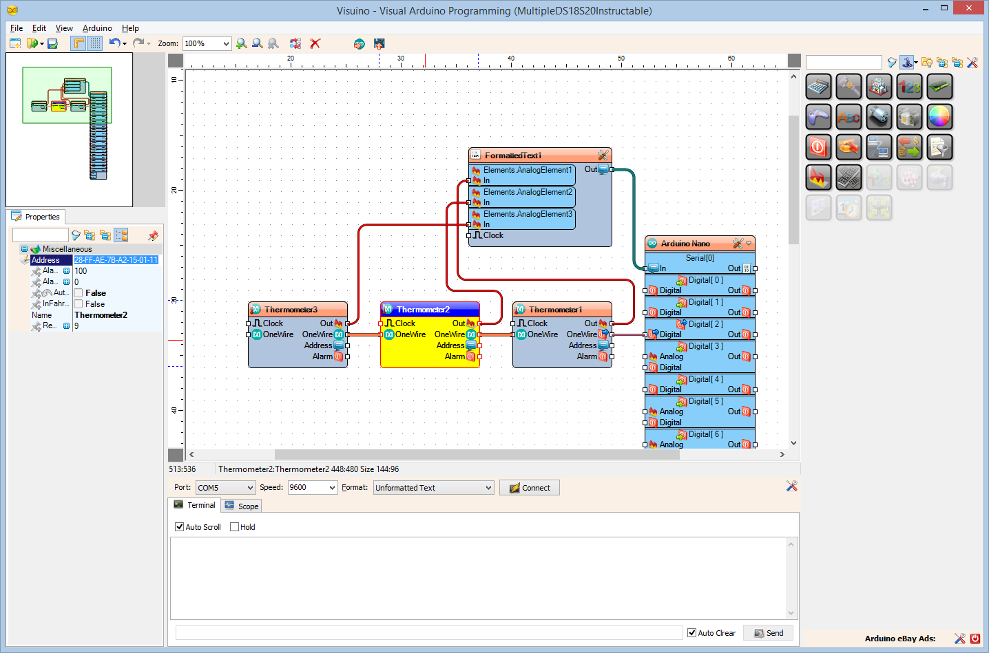
When working with multiple thermometers, the code will automatically discover the connected Thermometers, and will work with them. The Thermometers however will be discovered in random order. It is usually necessary to specify the address of the Thermometer for each component. In one of the previous Instructables, I already showed how you can get the Address of the Thermometer, and you can find the instructions here.
In this step you can use the already discovered Address:
- Select the Thermometer component for which you want to set the Address
- Set the value of the AutoDiscover property to False (Picture 1)
- Set the value of the Address property as shown on the (Picture 2)
Generate, Compile, and Upload the Arduino Code
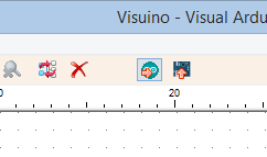
- In Visuino, Press F9 or click on the button shown on Picture 1 to generate the Arduino code, and open the Arduino IDE
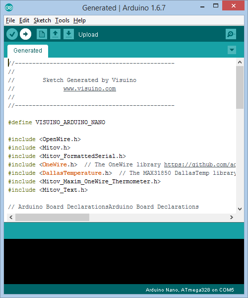
- In the Arduino IDE, click on the Upload button, to compile and upload the code (Picture 2)
If you get compiler error in the Arduino IDE, this means that you are missing at least one of the following libraries:
https://github.com/adafruit/MAX31850_OneWire
https://github.com/adafruit/MAX31850_DallasTemp
Look at the Next Step to see how to install them!
If Not Installed: Install the OneWire Thermometer Arduino Libraries From Adafruit
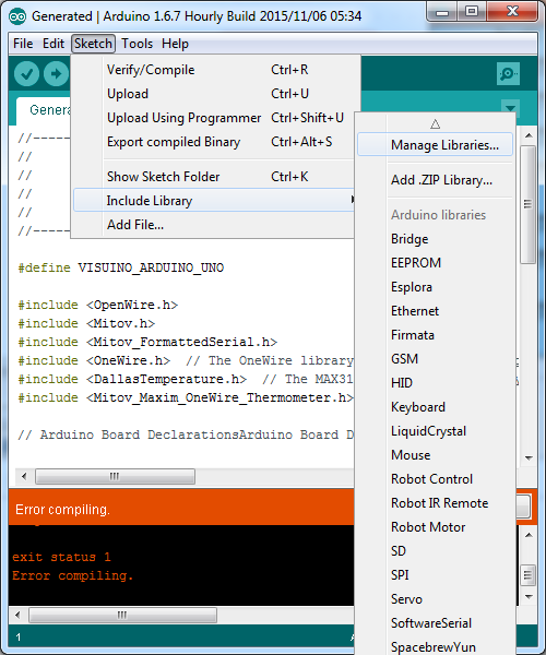
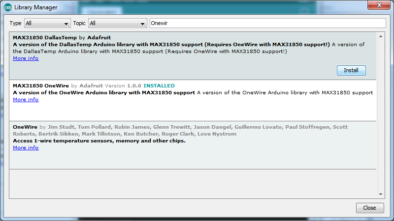
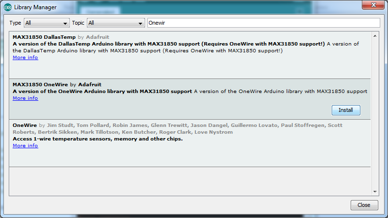
If you don't have the OneWire libraries already installed, follow these steps:
- In the Arduino IDE menu, select |Sketch|Include Library|Manage Libraries...| (Picture 1)
- Type "onewir" in the filter box (Picture 2)
- Select the MAX31850 OneWire by Adafruit library, and click the Install button (Picture 2)
- Select the MAX31850 DallasTemp by Adafruit library, and click the Install button (Picture 3)
- Click on the Close button (Picture 3)
- In the Arduino IDE, click on the Upload button, to compile and upload the code
And Play...
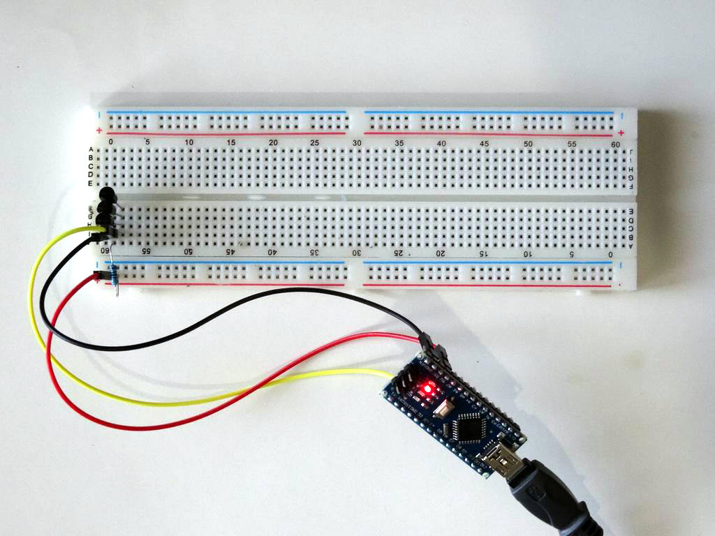
You can see the connected and running Thermometers on Picture 1.
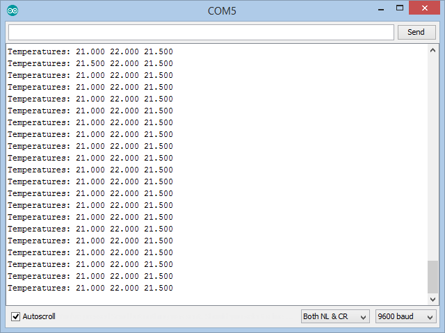
If you open Serial Terminal in the Arduino IDE or Visuino, you will see the Temperatures measured by the Thermometers (Picture 2).
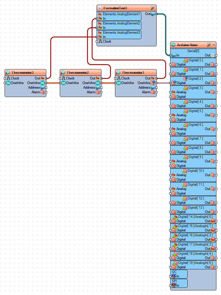
On Picture 3 you can see the complete Visuino diagram.
Also attached is the Visuino project, that I created for this Instructable.
You can download and open it in Visuino: https://www.visuino.com