Arduino Nano: Measure Distance With Ultrasonic Ranger and Log It to MicroSD Card With Visuino
by BoianM in Circuits > Arduino
8531 Views, 19 Favorites, 0 Comments
Arduino Nano: Measure Distance With Ultrasonic Ranger and Log It to MicroSD Card With Visuino

MicroSD Cards are cheap and easy data storage medium, and they are very convenient for storing Arduino sensor data. There are also a number of cheap readily available MicroSD Card Modules for Arduino.
In this Instructable, I will show you how easy it is to connect MicroSD Card Module to Arduino, and program it with Visuino to record Sensor data.
Components

- One Arduino compatible board (I use Arduino Nano, because I have one, but any other will be just fine)
- One MicroSD Card Module
- One MicroSD Card
- One Ultrasonic Ranger Sensor Module - I used HC-SR04, but US-015, or very much any other will also work
- One small Breadboard (Any breadboard can be used, or any other way to connect 3 wires together)
- 8 Female-Female jumper wires
- 3 Female-Male (Red) jumper wires
Connect the MicroSD Module to Arduino
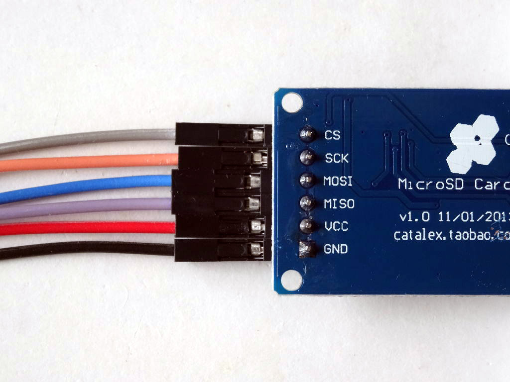
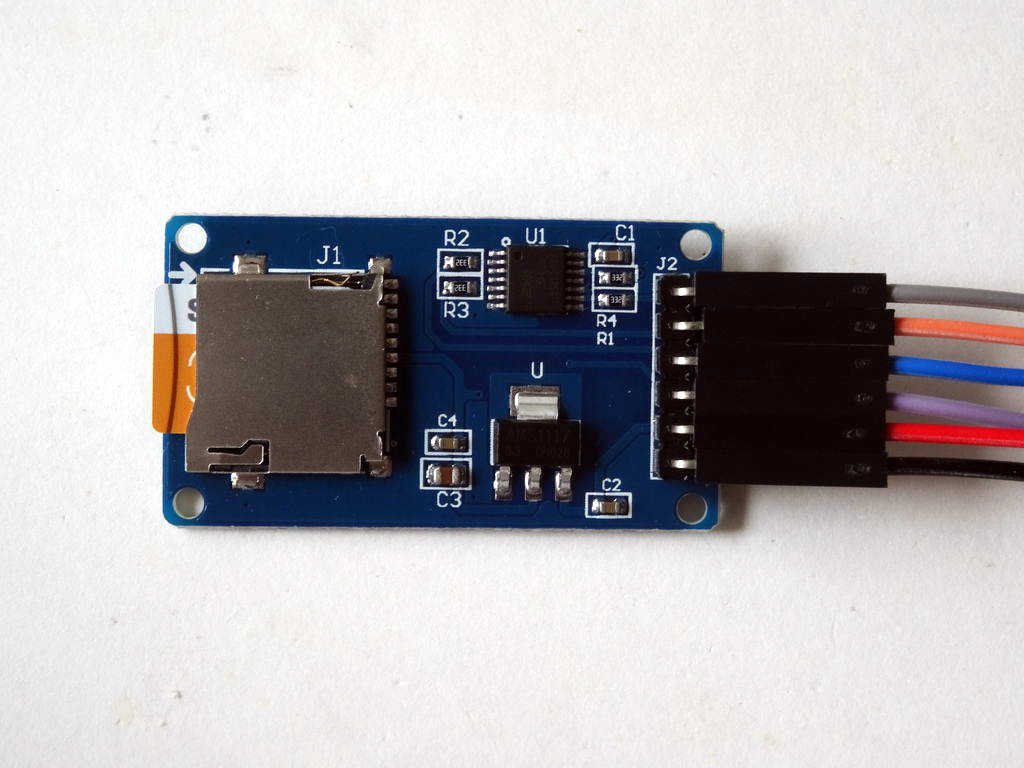
- Connect Female-Female CS(Gray Wire), SCK(Orange wire), MOSI(Blue wire), MISO(Purple wire), and Ground(Black wire) to the MicroSD Module
- Connect the Female end of a Female-Male Power(Red wire) to the VCC/Power pin of the MicroSD Module (Picture 1) , and leave the Male end unconnected
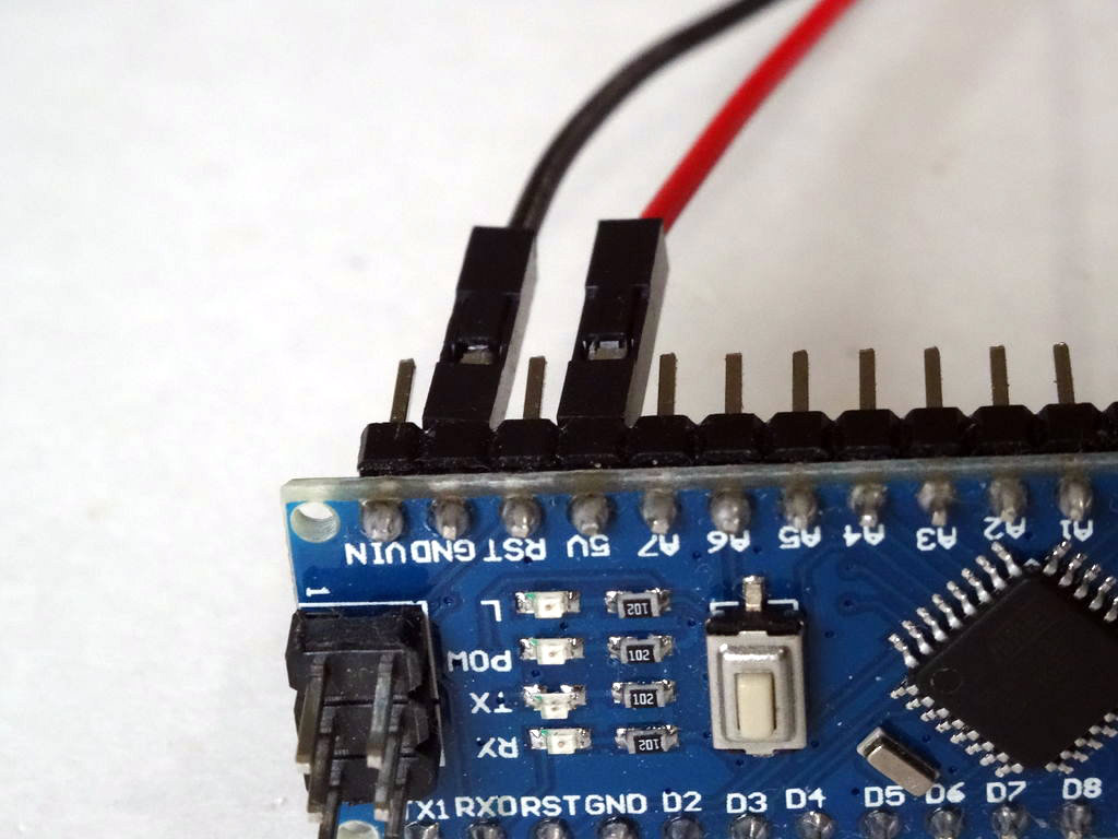
- Connect the other end of the Ground wire(Black wire) to Ground pin of the Arduino board(Picture 2)
- Connect another Female-Male Power wire(Red wire) to the 5V Power pin of the Arduino board(Picture 2), and leave the Male end unconnected
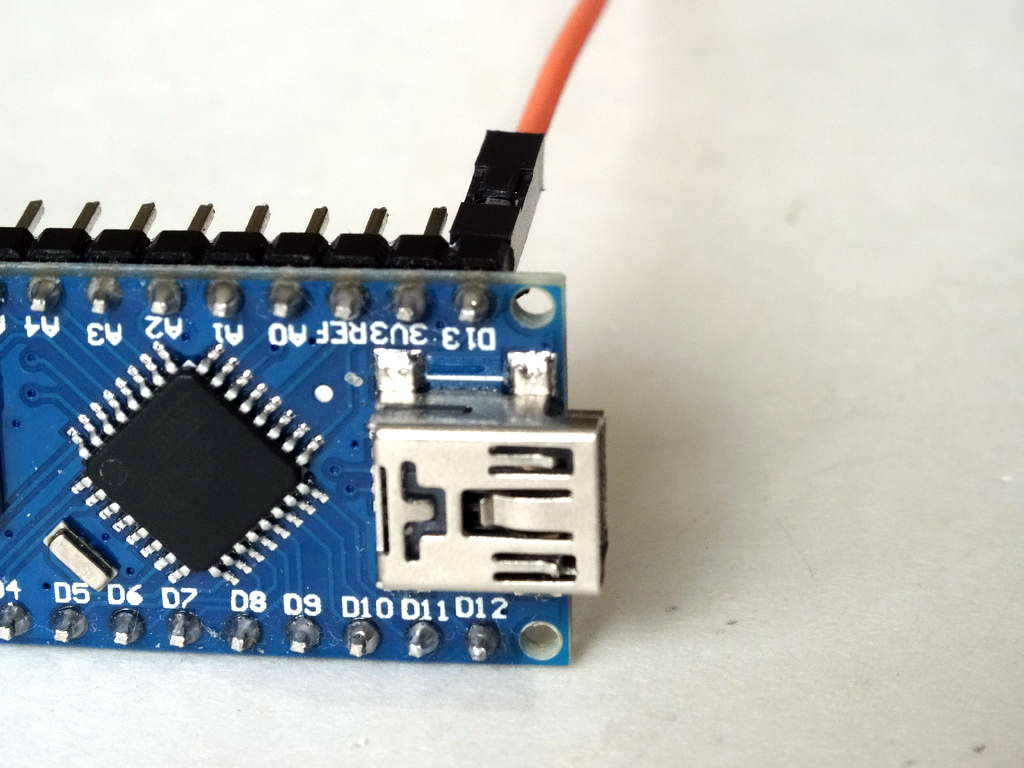
- Connect the other end of the SCK(Orange wire) to Digital pin 13 of the Arduino board(Picture 3)
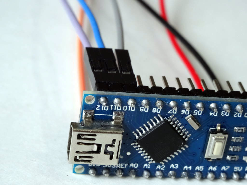
- Connect the other end of the MISO(Purple wire) to Digital pin 12 of the Arduino board(Picture 4)
- Connect the other end of the MOSI(Blue wire) to Digital pin 11 of the Arduino board(Picture 4)
- Connect the other end of the CS(Gray wire) to Digital pin 10 of the Arduino board(Picture 4)
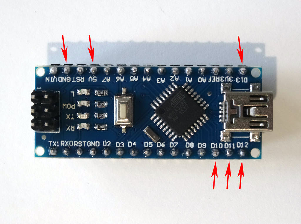
- Picture 5 shows in Red where are the Ground, 5V Power, Digital 10, Digital 11, Digital 12, and Digital 13 pins of the Arduino Nano
Connect the Ultrasonic Ranger to Arduino


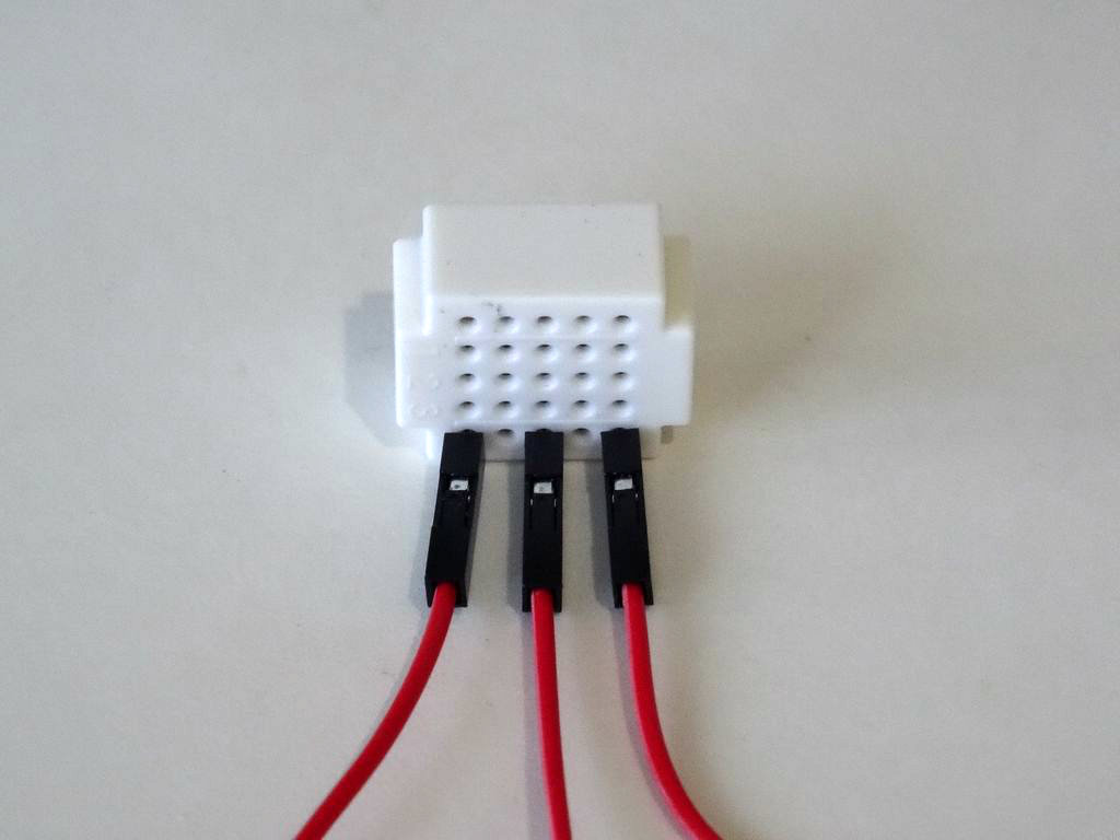
- Connect Female-Female Ground(Black wire), Trigger(Green wire), and Echo(Yellow wire) to the Ultrasonic Ranger Sensor Module (Picture 1)
- Connect the Female end of a Female-Male Power(Red wire) to the VCC/Power pin of the Ultrasonic Ranger Sensor Module (Picture 1) , and leave the Male end unconnected
- Connect the other end of the Ground wire(Black wire) to Ground pin of the Arduino board(Picture 2)
- Connect the other end of the Trigger wire(Green wire) to Digital pin 2 of the Arduino board(Picture 2)
- Connect the other end of the Echo wire(Yellow wire) to Digital pin 3 of the Arduino board(Picture 2)
- Picture 3 shows in Red where are the Ground, Digital 2, and Digital 3 pins of the Arduino Nano (In Blue are shown the connections made in the previous step)
Connect the Power Wires Together, and Plug the MicroSD Card in the Module
- Connect the Male ends of the 3 Power wires(Red wires) - from the Ultrasonic Ranger, the MicroSD Card Module, and the Arduino together as example with the help of a Breadboard (Picture 1) - In my case I used a small Breadboard
- Insert the MicroSD Card into the MicroSD Card Module (Picture 2)
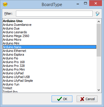
Start Visuino, and Select the Arduino Board Type

To start programming the Arduino, you will need to have the Arduino IDE installed from here: http://www.arduino.cc/.
Please be aware that there are some critical bugs in Arduino IDE 1.6.6.
Make sure that you install 1.6.7 or higher, otherwise this Instructable will not work!
The Visuino: https://www.visuino.com also needs to be installed.
In Visuino: Add and Connect Micro SD Card Module Component


First we need to add and connect MicroSD Component in Visuino to control the MicroSD Module:
- Type "sd" in the Filter box of the Component Toolbox then select the "Micro SD Card Module" component (Picture 1), and drop it in the design area
- Connect the "Out" pin of the SDCard1 component to the to the "In" pin of the "SPI" channel of the Arduino component (Picture 2)
- Connect the "ChipSelect" output pin of the SDCard1 component to the "Digital" input pin of the "Digital[ 10 ]" channel of the Arduino component (Picture 3)
In Visuino: Add and Configure File Element to the MicroSD Card Component


To record the data we need to add File element to the MicroSD component and specify its file name:
- Click on the "Tools" button of the SDCard1 component (Picture 1)
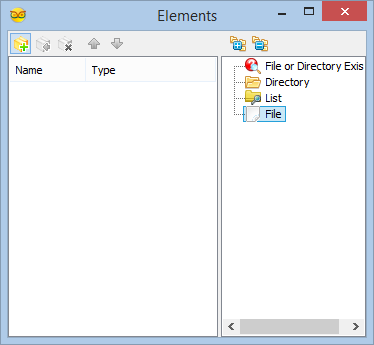
- In the "Elements" editor select the “File” element in the right window, and then click on the "+" button on the left (Picture 2) to add File element
- In the Object Inspector set the value of the "Path Name" property of the File1 Element to "Log.txt" (Picture 3)
In Visuino: Add and Connect Ultrasonic Ranger Component


Finally we need to add and connect a sensor to collect data, and send it to the File element of the MicroSD Module:
- Type "sonic" in the Filter box of the Component Toolbox then select the "Ultrasonic Ranger(Ping)" component (Picture 1), and drop it in the design area
- Connect the "Out" output pin of the UltrasonicRanger1 component to the "In" input pin of the "Elements.File1" of the SDCard1 component (Picture 2)
- Connect the "Ping(Trigger)" pin of the UltrasonicRanger1 component (Picture 3) to the "Digital" input pin of the Digital[ 2 ] channel of the Arduino component (Picture 4)
- Connect the "Out" pin of the Digital[ 3 ] channel of the Arduino component (Picture 5) to the "Echo" input pin of the UltrasonicRanger1 component (Picture 6)
In Visuino: Specify the Delay Between the Ultrasonic Ranger Measurements

In the Object Inspector set the value of the "Pause Time (mS)" property to "1000" so the Ultrasonic Ranger will pause for 1 second between the measurements (Picture 1)
Generate, Compile, and Upload the Arduino Code
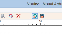

- In Visuino, Press F9 or click on the button shown on Picture 1 to generate the Arduino code, and open the Arduino IDE
- In the Arduino IDE, click on the Upload button, to compile and upload the code (Picture 2)
And Play...


Congratulations! You have completed the project.
Picture 1 and the Video show the connected and powered up project. The LED on Digital Pin 13 of the Arduino will start flashing once a second when new data from the Ultrasonic Ranger is recorded to the MicroSD Card.
On Picture 2 you can see example of the data recorded on the MicroSD Card.
On Picture 3 you can see the complete Visuino diagram.
Also attached is the Visuino project, that I created for this Instructable. You can download and open it in Visuino: https://www.visuino.com