Arduino Nano: HMC5883L Compass With Visuino
by BoianM in Circuits > Arduino
9212 Views, 28 Favorites, 0 Comments
Arduino Nano: HMC5883L Compass With Visuino
Components
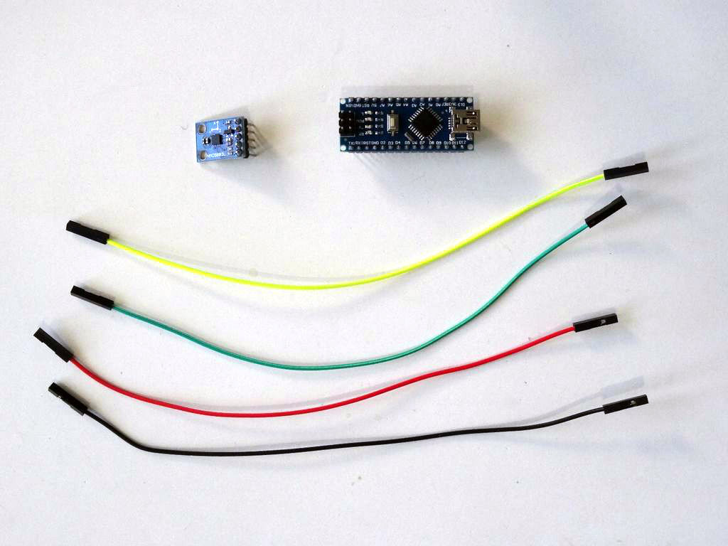
- One Arduino compatible board (I use Arduino Nano, because I have one, but any other will be just fine)
- One HMC5883L Compass Module
- 4 Female-Female jumper wires
Connect the HMC5883L Compass to Arduino
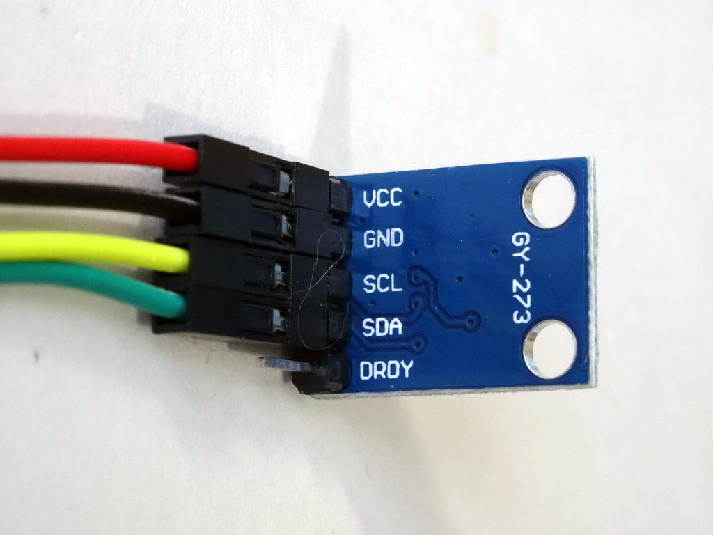
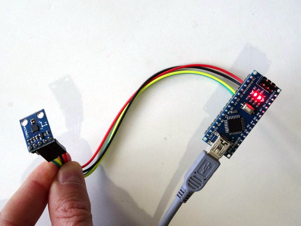
- Connect 5V VCC Power(Red wire), Ground(Black wire), SCL(Yellow wire), and SDA(Green wire), to the HMC5883L Compass Module (Picture 1)
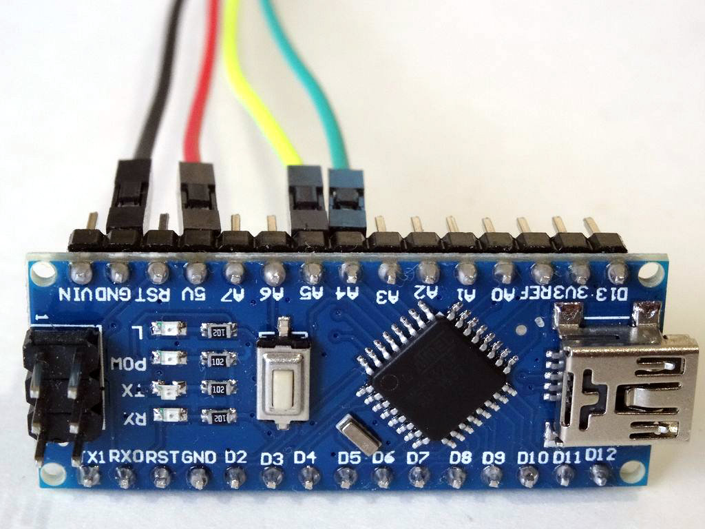
- Connect the other end of the Ground wire(Black wire) to Ground pin of the Arduino board (Picture 2)
- Connect the other end of the 5V VCC Power wire(Red wire) to the 5V power pin of the Arduino board (Picture 2)
- Connect the other end of the SDA wire(Green wire) to SDA/Analog pin 4 of the Arduino Nano board (Picture 2)
- Connect the other end of the SCL wire(Yellow wire) to SCL/Analog pin 5 of the Arduino Nano board (Picture 2)
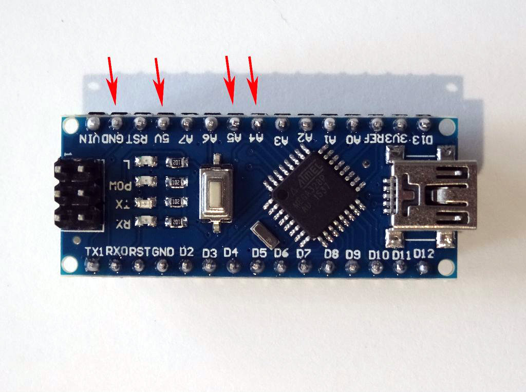
- Picture 3 shows where are the Ground, 5V Power, SDA/Analog pin 4, and SCL/Analog pin 5, pins of the Arduino Nano
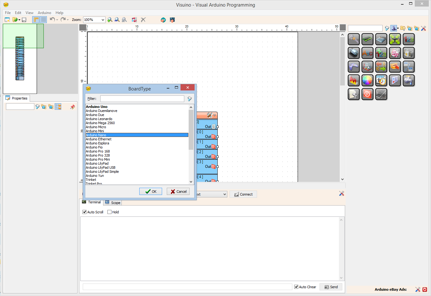
Start Visuino, and Select the Arduino Board Type
To start programming the Arduino, you will need to have the Arduino IDE installed from here: http://www.arduino.cc/.
Please be aware that there are some critical bugs in Arduino IDE 1.6.6.
Make sure that you install 1.6.7 or 1.6.5, otherwise this Instructable will not work!
The Visuino: https://www.visuino.com also needs to be installed.
In Visuino: Add Compass, Compass Heading and Formatted Text Components
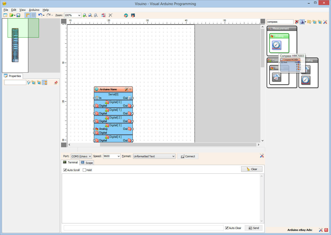
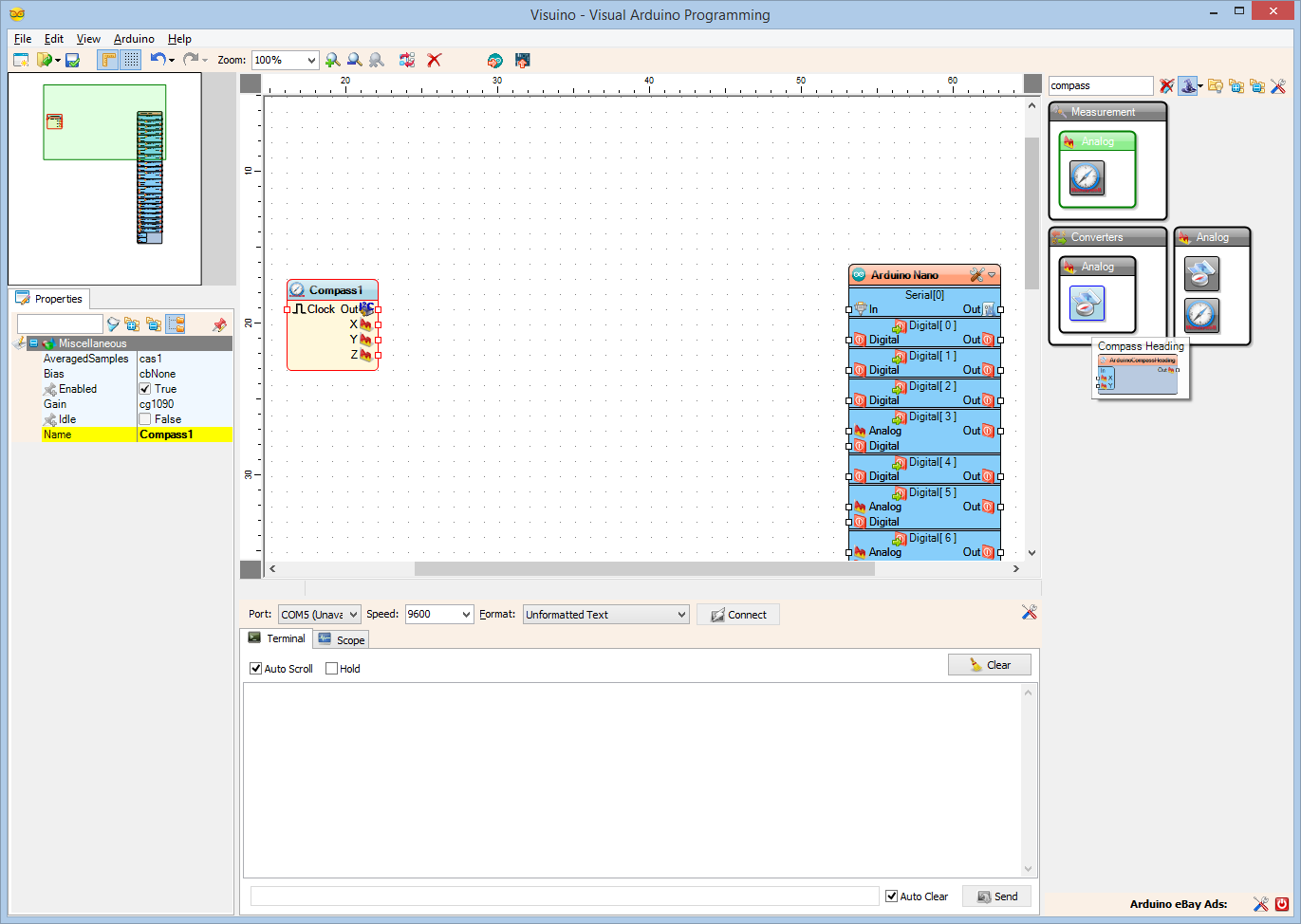
- Type "compass" in the Filter box of the Component Toolbox then select the "Compass HMC5883" component (Picture 1), and drop it in the design area
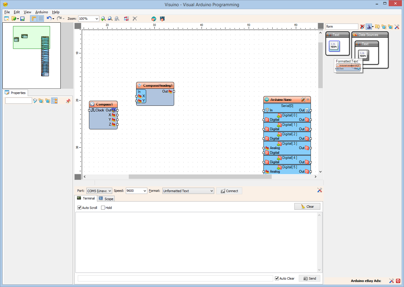
- From the Component Toolbox select the "Compass Heading" component (Picture 2), and drop it in the design area
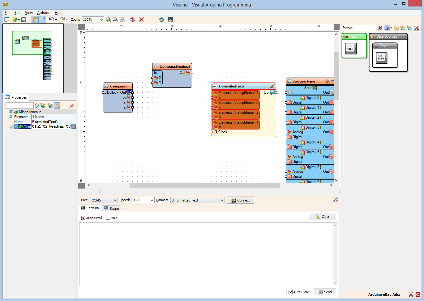
- Type "form" in the Filter box of the Component Toolbox then select the "Formatted Text" component (Picture 3), and drop it in the design area
In Visuino: Add the Text Elements, and Specify Formatted Text
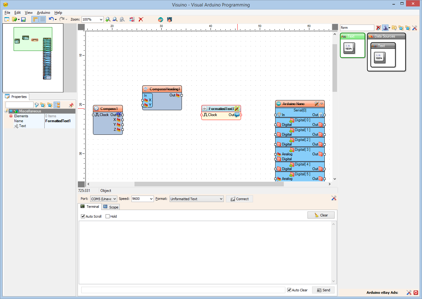
- Click on the "Tools" button of the FormattedText1 component
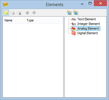
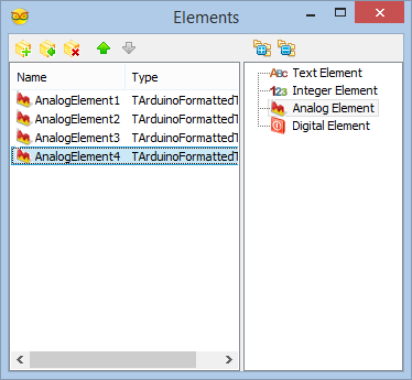
- In the Elements editor, Select the Analog Element on the right, and click 4 times on the "+" button on the left on the to add 4 of them (Picture 2, and 3), then close the Elements editor
- Set the value of the Text property of the FormattedText1 component to "X: %0 Y: %1 Z: %2 Heading: %3" (Picture 4). The %0 will be replaced with the value from AnalogElement1, %1 will be replaced with the value from AnalogElement2, %2 will be replaced with the value from AnalogElement3, and %3 will be replaced with the value from AnalogElement4
In Visuino: Connect the Compass Components
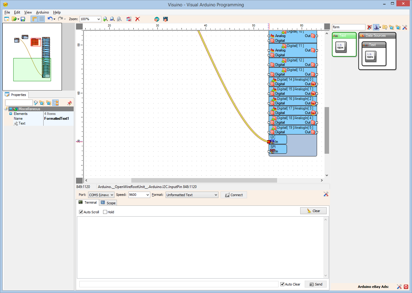
- Connect the "Out" pin of the Compass1 component (Picture 1) to the to the "In" pin of the I2C channel of the Arduino component (Picture 2)
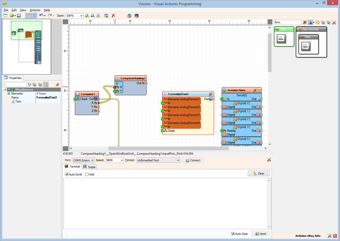
- Connect the "X" output pin of the Compass1 component to the "X" pin of the "In" pins of the CompassHeading1 component (Picture 3)
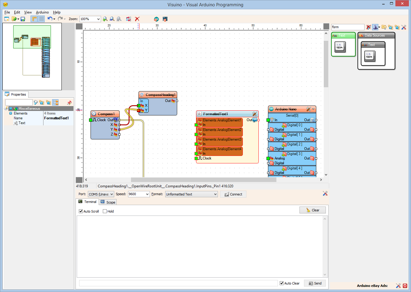
- Connect the "Y" output pin of the Compass1 component to the "Y" pin of the "In" pins of the CompassHeading1 component (Picture 4)
In Visuino: Connect the Formatted Text Component
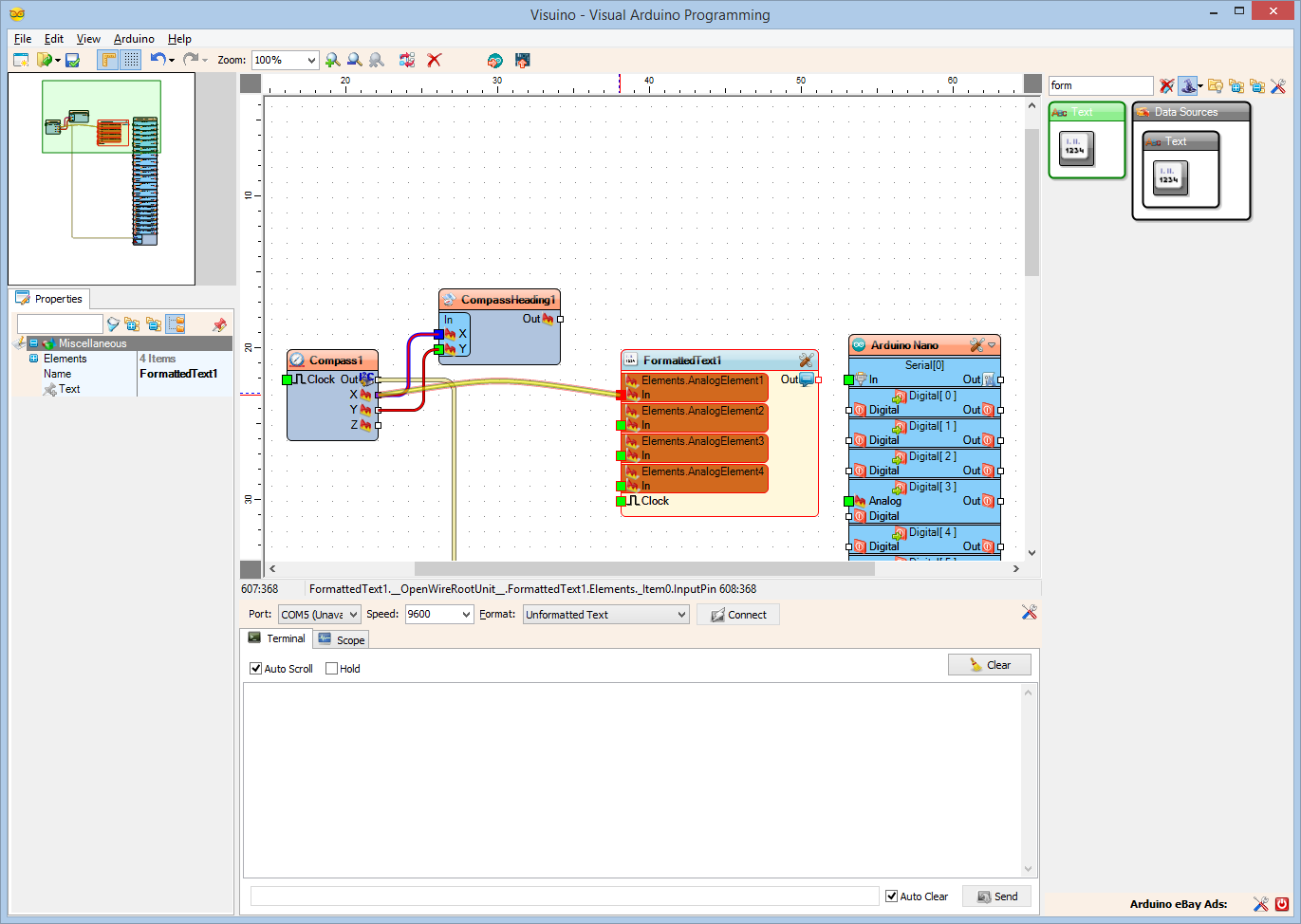
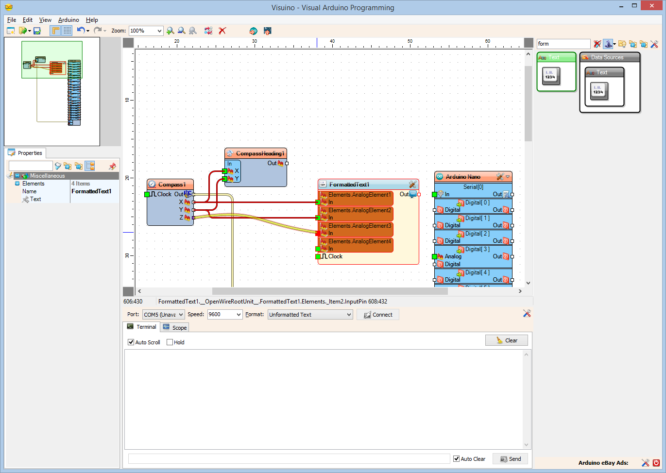

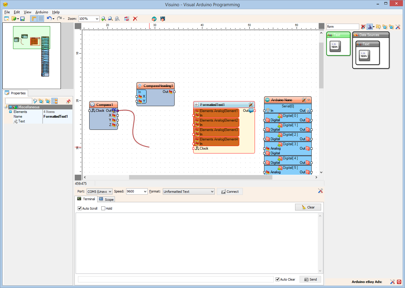
- Connect the "X" output pin of the Compass1 component to the "In" pin of the AnalogElement1 of the FormattedText1 component (Picture 1)
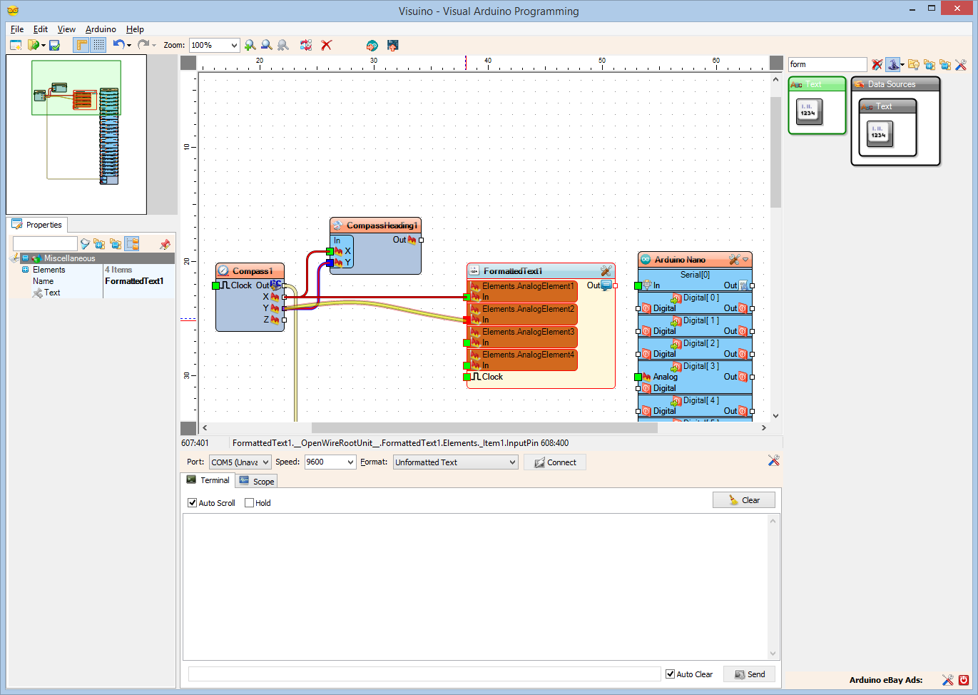
- Connect the "Y" output pin of the Compass1 component to the "In" pin of the AnalogElement2 of the FormattedText1 component (Picture 2)
- Connect the "Z" output pin of the Compass1 component to the "In" pin of the AnalogElement3 of the FormattedText1 component (Picture 3)
- Connect the "Out" output pin of the CompassHeading1 component to the "In" pin of the AnalogElement4 of the FormattedText1 component (Picture 4)
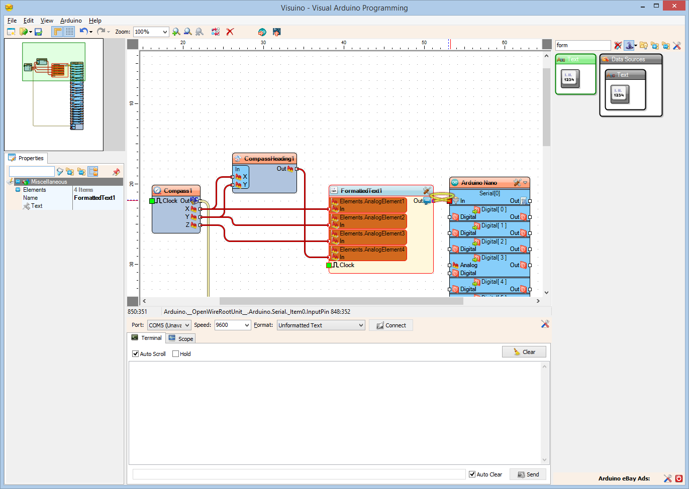
- Connect the "Out" output pin of the FormattedText1 component to the "In" input pin of the "Serial[ 0 ]" channel of the Arduino component (Picture 5)
Generate, Compile, and Upload the Arduino Code
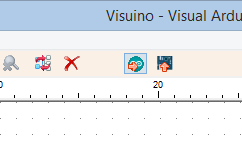
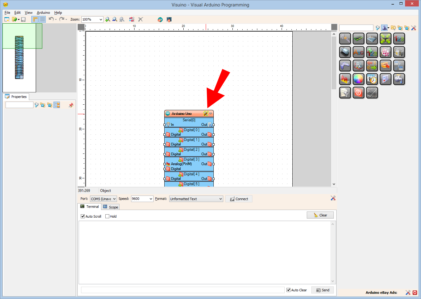
- In Visuino, Press F9 or click on the button shown on Picture 1 to generate the Arduino code, and open the Arduino IDE
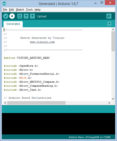
- In the Arduino IDE, click on the Upload button, to compile and upload the code (Picture 2)
And Play...
Congratulations! You have completed the project.
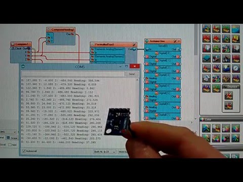
Picture 1 shows the connected and powered up project.
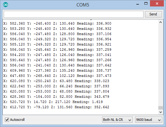
If you open Serial Terminal in the Arduino IDE or Visuino, you will see the X, Y, and Z magnetic values, as well as the calculated X,Y heading in degrees (Picture 2)
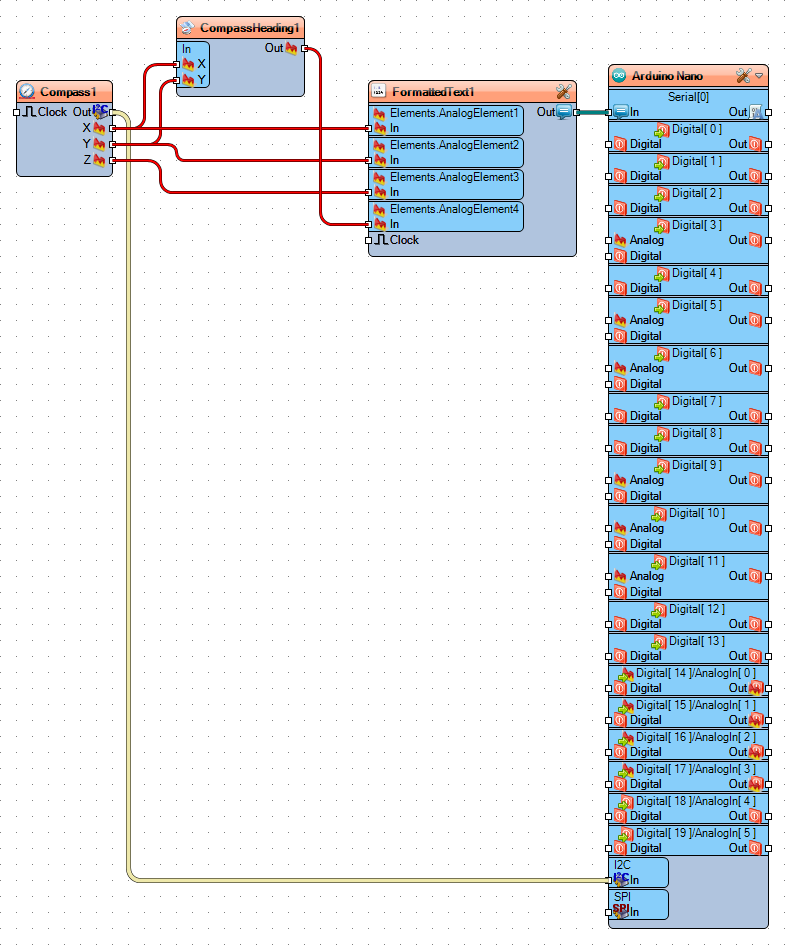
On Picture 3 you can see the complete Visuino diagram.
Also attached is the Visuino project, that I created for this Instructable. You can download and open it in Visuino: https://www.visuino.com