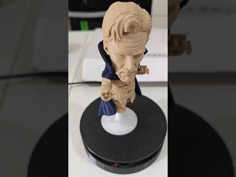
Arduino - DIY 3D Printed Rotating Table
by GeppettoIndustries in Circuits > Arduino
2153 Views, 17 Favorites, 0 Comments
Arduino - DIY 3D Printed Rotating Table

☕ Support the Project
All my projects are shared for free, with the goal of helping and inspiring others in the maker and open-source community.
If you’d like to support my work and help me keep creating new projects, you can make a small donation:
👉 Donate via PayPal: https://www.paypal.com/donate/?hosted_button_id=V6D9QA874HT58
Your support — no matter how small — makes a big difference.
Thank you for keeping these projects alive and accessible to everyone! 🙌
Welcome to this comprehensive guide on creating your DIY 3D Printed Rotating Display Table! Whether you're an enthusiast looking to showcase your latest 3D printed models, a hobbyist needing a dynamic platform for your collectibles, or a professional seeking an innovative way to present products, this project is perfect for you.
In this instructable, we will walk you through the process of designing, printing, and assembling a rotating display table from scratch. Leveraging the versatility of 3D printing, you’ll be able to customize every aspect of your display table, ensuring it meets your specific needs and aesthetic preferences.
Our project is designed to be accessible for beginners while still offering plenty of opportunities for more experienced makers to flex their creative muscles. You’ll learn how to:
- Design a sturdy and stylish base using 3D modeling software
- Print the components with optimal settings for strength and durability
- Assemble the rotating mechanism using commonly available parts
- Add optional features like lighting and speed control to enhance the display
By the end of this instructable, you'll have a functional and visually appealing rotating display table, perfect for elevating your presentations and impressing your audience. So, let’s get started and bring your displays to life with motion and style!
Supplies
Before we dive into the step-by-step instructions, let's gather all the necessary supplies you'll need to build your DIY 3D Printed Rotating Display Table. Here’s a list of components and materials required for this project:
Electronic Components
- Arduino Nano: The microcontroller that will control the rotation of the display table.
- 28BYJ-48 Stepper Motor with ULN2003 Driver: This compact and affordable stepper motor, paired with its driver, will provide the precise control needed for smooth rotation.
- DC Power Plug: To power the Arduino Nano and the stepper motor, ensuring a stable and reliable power supply.
3D Printing Materials
- PLA Filament: or any other filament suitable for your 3D printer, available in the color of your choice. PLA is recommended for its ease of use and good strength.
- 3D Printer: A reliable 3D printer capable of printing with fine details and accuracy.
Additional Supplies
- Jumper Wires: For connecting the Arduino Nano to the stepper motor driver and other components.
- USB Cable: For programming the Arduino Nano.
- Power Supply or PowerBank: A compatible power adapter to connect to the DC power plug and supply the necessary voltage.
Tools
- Hot Glue Gun or Super Glue: For securing parts that may need a stronger hold.
- Soldering Iron and Solder: Optional, for more permanent and secure connections between wires and components.
With these supplies ready, you’ll be equipped to follow along with the build process and create a functional and eye-catching rotating display table. Let’s move on to the design phase and get started on this exciting project!
3D Print the Rotating Display Table Components
Now that you have already modeled the rotating display table, the first step in bringing your project to life is to 3D print all the necessary components. Follow these detailed instructions to ensure you achieve high-quality prints.
What You Will Need:
- 3D Printer
- PLA Filament (or your preferred filament)
- Slicing Software (e.g., Cura, PrusaSlicer)
Instructions:
- Prepare Your 3D Printer:
- Ensure your 3D printer is properly calibrated. This includes checking the bed leveling, ensuring the extruder is clean, and verifying that the filament is loaded correctly.
- Preheat the printer to the recommended temperature for your filament.
- Load the 3D Models:
- Import your pre-modeled 3D parts into your slicing software. Common file formats include .STL or .OBJ.
- Configure Print Settings:
- Set the layer height to 0.2 mm for a good balance between detail and print time.
- Use a wall thickness of at least 1.2 mm for added strength.
- Set the infill density to around 20-30% for sturdy but not overly heavy parts.
- Enable supports if necessary, depending on the complexity of the parts. Ensure the support settings are optimized for easy removal.
- Slice the Model:
- Slice the 3D models to generate the G-code, which will be used by the 3D printer to produce the parts.
- Review the sliced model preview to ensure there are no errors and that the support structures are correctly placed.
- Start Printing:
- Transfer the G-code to your 3D printer via an SD card or direct USB connection.
- Begin printing each component, starting with larger or more complex parts first. This ensures you have ample time to troubleshoot any issues with the most critical pieces.
- Monitor the first few layers of each print to ensure proper adhesion to the print bed.
With all your parts printed and ready, you are now set to move on to the next steps: assembling the components and integrating the electronics.
Upload the Arduino Code
With your 3D printed parts ready, the next step is to program the Arduino Nano to control the stepper motor. The following code will manage the rotation of the display table, allowing for direction and speed control.
What You Will Need:
- Arduino Nano
- USB Cable for Arduino Nano
- Arduino IDE (downloadable from here)
- Computer
Instructions:
- Install Arduino IDE:
- If you haven't already, download and install the Arduino IDE from the Arduino website.
- Connect the Arduino Nano:
- Connect your Arduino Nano to your computer using the USB cable.
- Open the Arduino IDE:
- Launch the Arduino IDE on your computer.
- Select the correct board and port: Go to Tools > Board and select "Arduino Nano". Then, go to Tools > Port and select the port to which your Nano is connected.
- Enter the Code:
- Download the code in the attachment and open on the Arduino IDE:
- Upload the Code:
- Click the "Verify" button (checkmark icon) to compile the code.
- If there are no errors, click the "Upload" button (right arrow icon) to upload the code to your Arduino Nano.
- Verify the Upload:
- Once the upload is complete, the Arduino Nano should begin controlling the stepper motor according to the code.
Important Tips:
- Adjust Speed and Direction: If you wish to adjust the speed or direction of the rotation, you can modify the speed and direction variables in the code:
- Speed: Lower values make the motor spin faster; higher values make it slower.
- Direction: Set direction to false for counter-clockwise rotation or true for clockwise rotation.
- Testing: It's a good idea to test the setup on a breadboard before finalizing the connections to ensure everything works as expected.
CODE Explanation:
- Pin Definitions: IN1 to IN4 are defined as the control pins connected to the stepper motor driver.
- Step Sequence: stepSequence is a 2D array defining the sequence of steps to rotate the stepper motor. Each sub-array represents one step with four control signals.
- Direction and Speed Variables: direction determines the rotation direction, and speed controls the speed of the motor.
- Setup Function: Sets the control pins as outputs.
- Loop Function: Runs continuously, controlling the motor rotation based on the direction. It iterates through the stepSequence array either forwards or backwards.
- setStep Function: Sets the motor control pins to the specified values for each step.
This commented code should help you understand how each part functions and how it controls the stepper motor for your rotating display table.
Downloads
Assembling the 3D Printed Rotating Display Table


Now that you have all your 3D printed parts and the Arduino Nano programmed, it's time to assemble your rotating display table. Follow these steps to bring your project together.
What You Will Need:
- 3D Printed Parts
- Arduino Nano
- 28BYJ-48 Stepper Motor with ULN2003 Driver
- DC Power Plug
- Jumper Wires
- Screwdriver Set
- Hot Glue Gun or Super Glue (optional)
- Breadboard (optional for initial testing)
- Power Supply (compatible with your DC Power Plug and Arduino Nano)
Instructions:
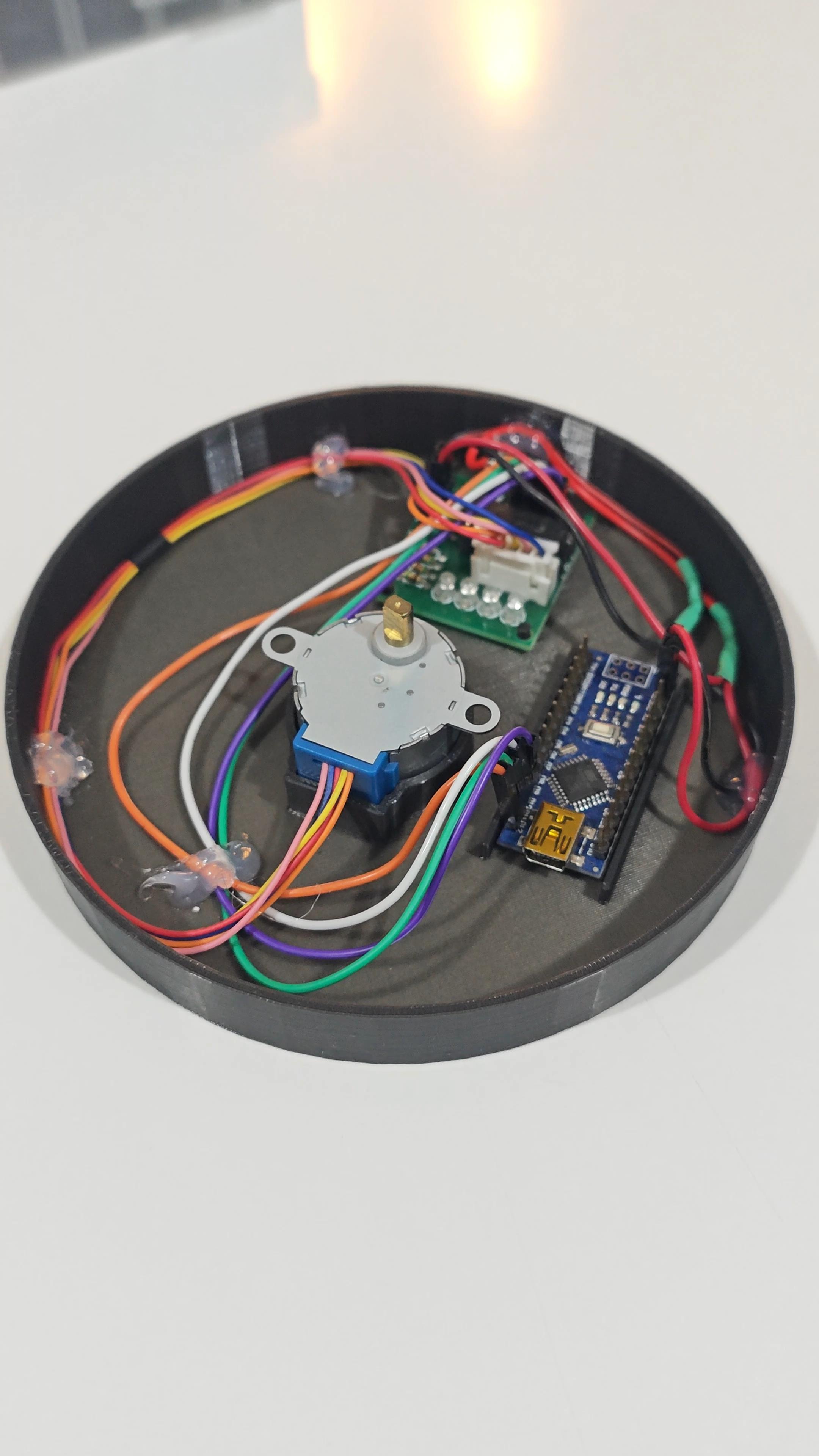
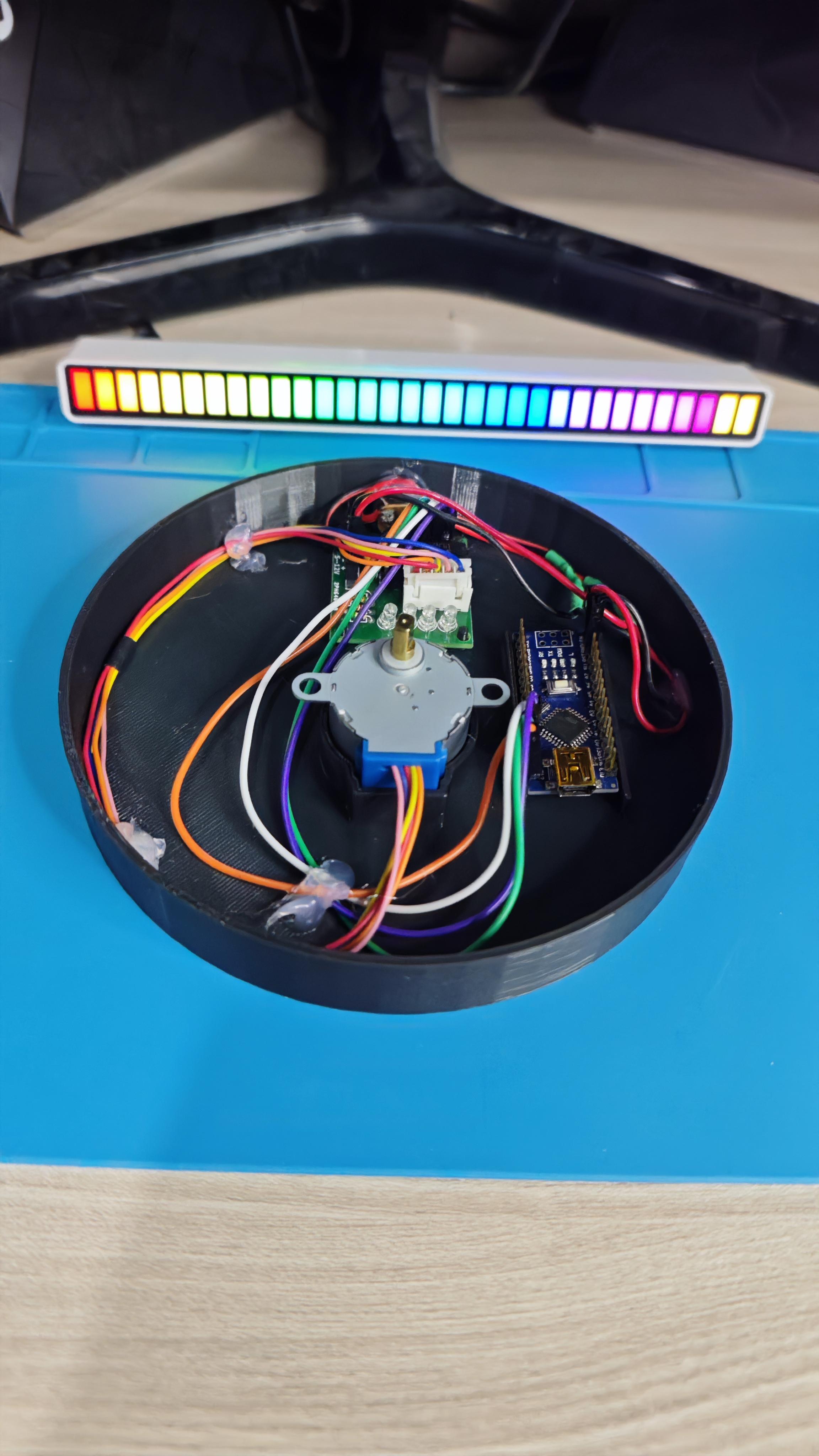
- Attach the Stepper Motor to the Base:
- Take the 3D printed base and securely mount the 28BYJ-48 stepper motor using the provided hole.
- Ensure the motor shaft is centered and aligned with the rotating platform.
- Connect the Stepper Motor to the ULN2003 Driver:
- Connect the motor's connector to the ULN2003 driver board. The connector should only fit one way, ensuring proper orientation.
- Mount the Arduino Nano:
- Secure the Arduino Nano to its designated spot in your 3D printed base.
- Wire the Stepper Motor Driver to the Arduino Nano:
- Use jumper wires to connect the ULN2003 driver to the Arduino Nano as follows:
- IN1 (driver) to pin 9 (Arduino)
- IN2 (driver) to pin 10 (Arduino)
- IN3 (driver) to pin 11 (Arduino)
- IN4 (driver) to pin 12 (Arduino)
- Connect the GND and VCC pins of the driver to the GND and 5V pins on the Arduino Nano.
- Connect the DC Power Plug:
- Wire the DC power plug to the Arduino Nano and the stepper motor driver.
- Ensure the polarity matches: the positive terminal should connect to the VIN pin on the Arduino and the VCC on the driver, while the negative terminal connects to the GND pins.
- Assemble the Rotating Platform:
- Attach the 3D printed rotating platform to the stepper motor shaft.
- Test the Setup:
- Before finalizing the assembly, it’s a good idea to test the setup.
- Power on the system and ensure the platform rotates as expected. Adjust the speed and direction in the code if necessary.
- Make sure the platform rotates smoothly without any obstructions or misalignments.
- Finalize the Assembly:
- Once tested, securely fasten all parts, ensuring there are no loose components.
- If desired, use a hot glue gun or super glue to reinforce connections and keep wires in place.
Important Tips:
- Cable Management: Keep the wiring neat and organized to prevent tangling or interference with the rotating parts.