Arduino LoRa Sensor With InAir9B Radio
by iVladislav in Circuits > Arduino
9627 Views, 22 Favorites, 0 Comments
Arduino LoRa Sensor With InAir9B Radio
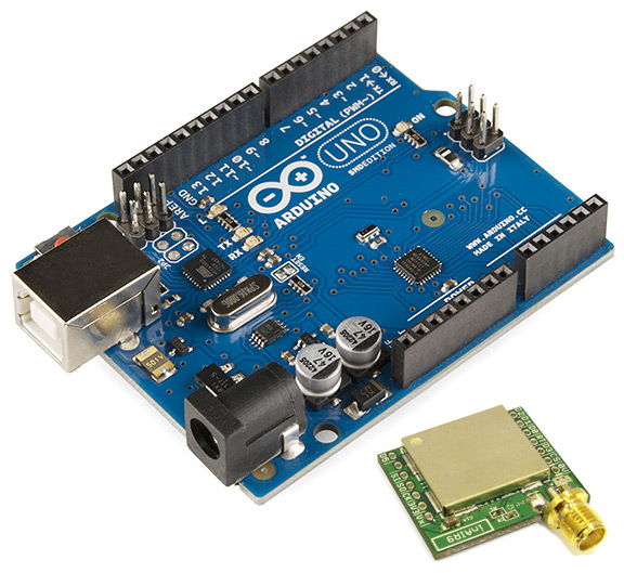
Here I will describe step by step how to make working LoRa sensor with LoRaWAN stack based on inAir9B module and Arduino UNO (same may be applied to Mega).
Haven't found a complete tutorial anywhere on the Web and decided to make it.
In the end you will have ready to use LoRa end node sending 'Hello World' message every minute.
As it is an example of LoRaWAN I assume you already have LoRa gateway.
What you will need:
1. Arduino UNO (Mega or other)
2. inAir9B module (of cause you may try the same with other module but it is out of scope of this guide)
3. Wires and breakboard
4. LoRa gateway
5. PC or laptop with Arduino IDE
6. LoRa Network server to see your data coming (I use loriot.io here)
Preparation:
Connect Gateway to your network server:
1) the easiest way is to use free account on loriot.io. Register there and add your gateway. It provides all instructons to setup your gateway and download customized software if required. When you are done with it you'll see your Gateway as 'online' and 'Connected'
2) Create a Network Application in your sever.
3) Generate new device in your application. This will give you settings like 'Device EUI', DevADDR, NWKSKEY, APPSKEY and some others which we don't need now.
Wiring Module
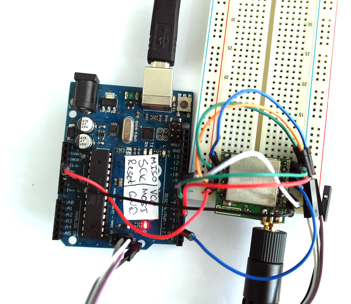
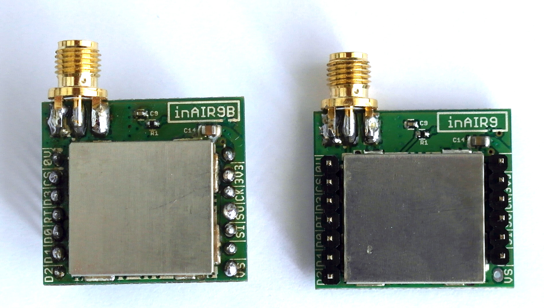
Some of my modules inAir9B was with soldered legs (right on the picture) and some I soldered by myself (left on the picture). Presoldered modules have legs above the labels which is not convinient from my POV because if you use breadboard you can't see what's written on it. So my modules I soldered with legs down. But it's up to you what to choose.
Connect inAir9B to Arduino as follows:
inAir9B - Arduino
D0 - 2
D1 - 5
D2 - 6
CS - 10
0V -GND
3V3 - 3.3V
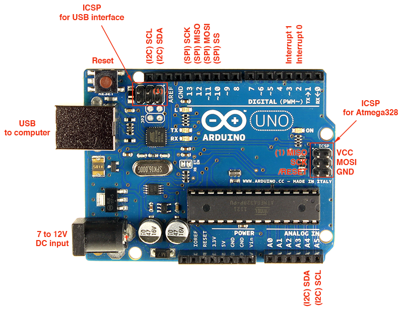
SI - MOSI (on ICSP header)
SO - MISO (on ICSP header)
CK - SCK (on ICSP header)
For pins on ICSP header see picture
Programming
.png)
There are currently 2 versions of LoRaWAN libraries for Arduino:
1. https://github.com/matthijskooijman/arduino-lmic - this library is ported from IBM LoRaWAN in C library. The problem with it is that it uses a lot of memory (mostly because of AES encription part) and could not be used as is on Arduino UNO because of that. But it can be used after disabling some features (which make code smaller).
2. https://github.com/things4u/LoRa-LMIC-1.51 - this is the same port from IBM library but with different lib for AES encription (smaller version).
I had problems with running a sketch from second option and decided to stop on the first one.
To do the same you should download library from the link above (Matthijs Kooijman version) and put it in your Arduino 'libraries' folder (unzipped). Then restart Arduino IDE and you will see it in libraries and Examples.
First of all go to the folder with library and open 'config.h' file. Check that line
'#define CFG_sx1276_radio 1' is uncommented and '//#define CFG_sx1272_radio 1' is commented.
Uncomment lines '#define DISABLE_PING' and '#define DISABLE_BEACONS' to save space for Arduino UNO (for Mega you can skip this).
Then open in Arduino IDE: File -> Examples -> IBM LMIC framework -> ttn
Check pins, should be like this:
// Pin mapping
const lmic_pinmap lmic_pins = { .nss = 10, .rxtx = LMIC_UNUSED_PIN, .rst = 5, .dio = {2, 5, 6}, };
Set NWKSKEY, APPSKEY, DEVADDR as you managed it in your Network server.
See attached files as example.
Upload your sketch to Arduino. Done!
It will start sending packages to your gateway and then forwarded to Network Server.
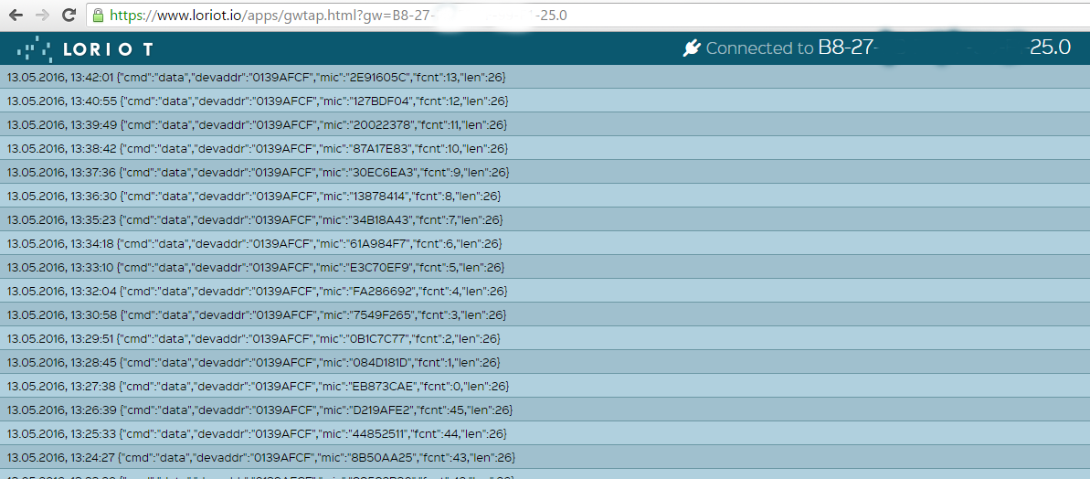
If you use 'loriot' you may see packets going to your server on page: https://www.loriot.io/apps/gwtap.html?gw=B8-27-EB-... ( put MAC of your GW here)
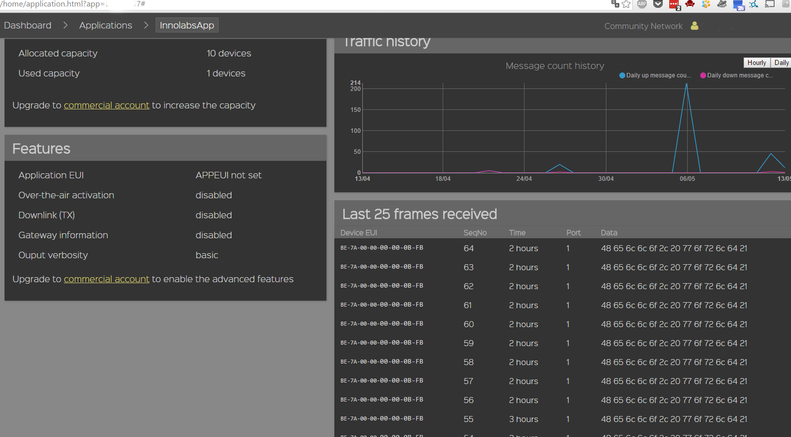
And also you may check messages coming in your server (see pictures).
You may convert HEX to ASCII data here: http://www.rapidtables.com/convert/number/hex-to-a...
In my case '48 65 6c 6c 6f 2c 20 77 6f 72 6c 64 21' means 'Hello, world!'
Next steps:
Connect your real sensors to arduino and program it to send data instead of "Hello World".