Arduino - Line Follower Robot
by MertArduino in Circuits > Arduino
69839 Views, 97 Favorites, 0 Comments
Arduino - Line Follower Robot
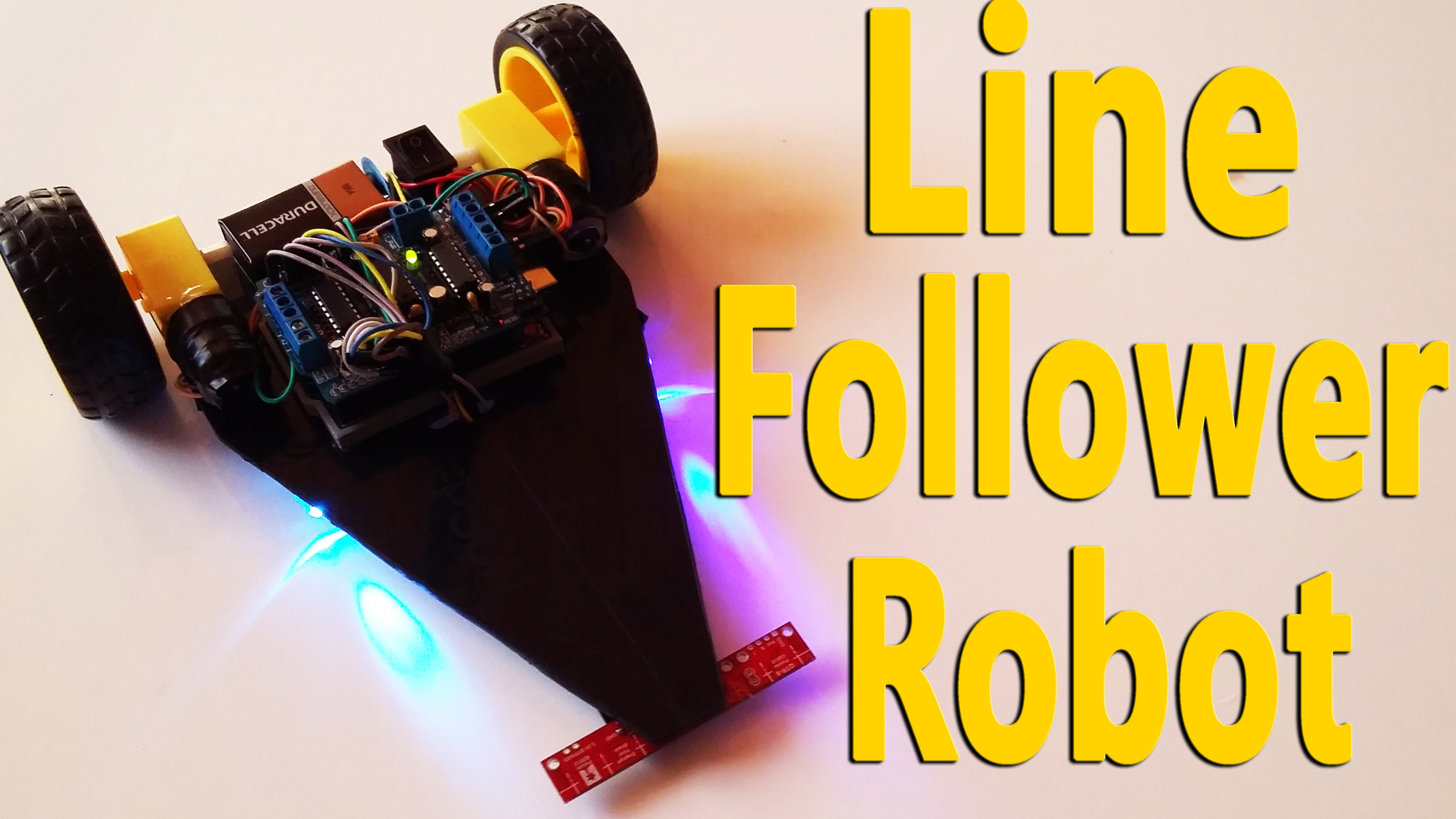
Arduino Project Tutorial Line Follower Robot - For beginners
In this tutorial, you will make line follower robot.
Video Tutorial
This tutorial involves building a line follower robot with an QTR-8RC Reflectance Sensor Array.
Hardware Required
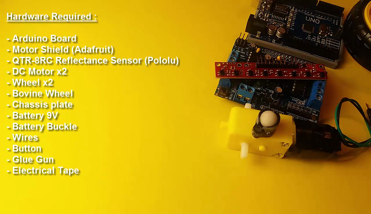
- Arduino Board
- Motor Shield (Adafruit)
- QTR-8RC Reflectance Sensor Array (Pololu)
- DC Motor x2
- Wheel x2
- Bovine Wheel
- Chassis plate
- Battery 9V
- Battery Buckle
- Wires
- Button
- Glue Gun
- Electrical Tape
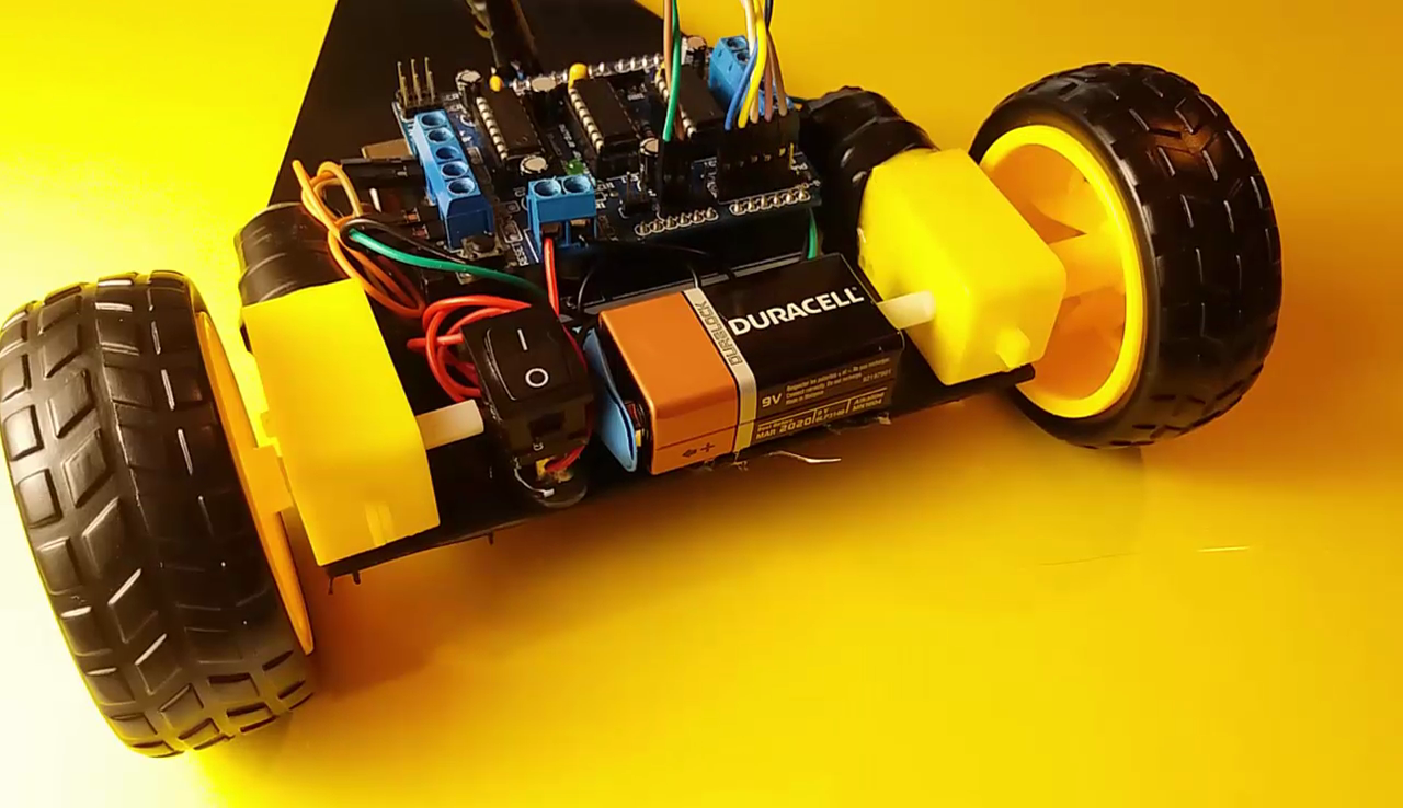
Create of the Chassis
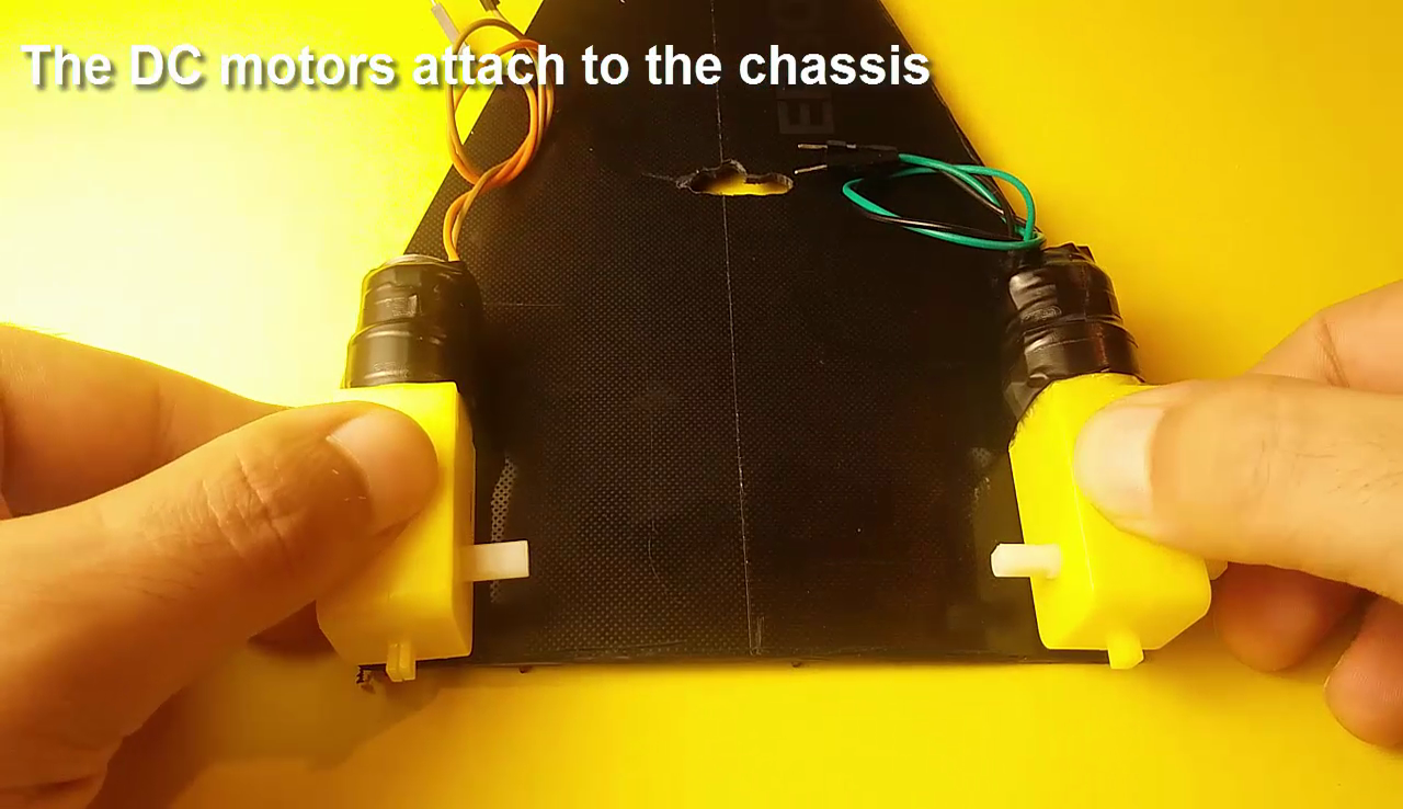
- The DC motors attach to the chassis
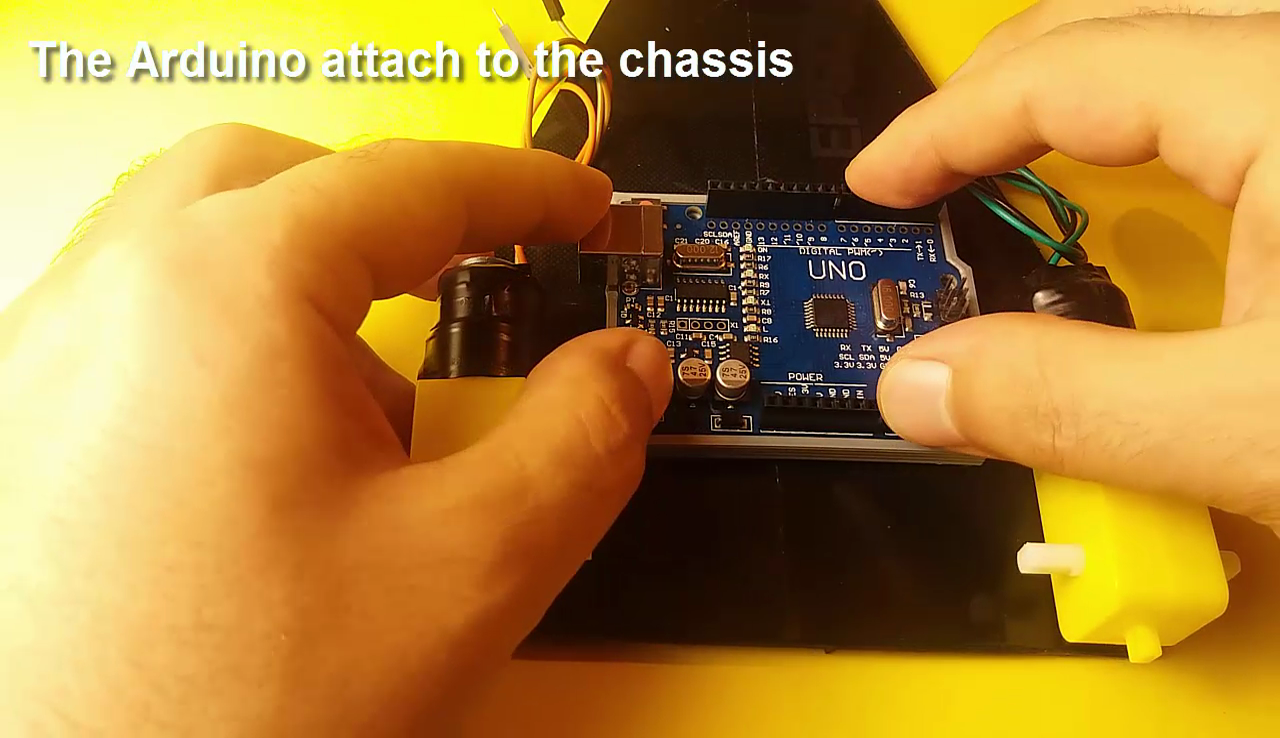
- The Arduino attach to the chassis
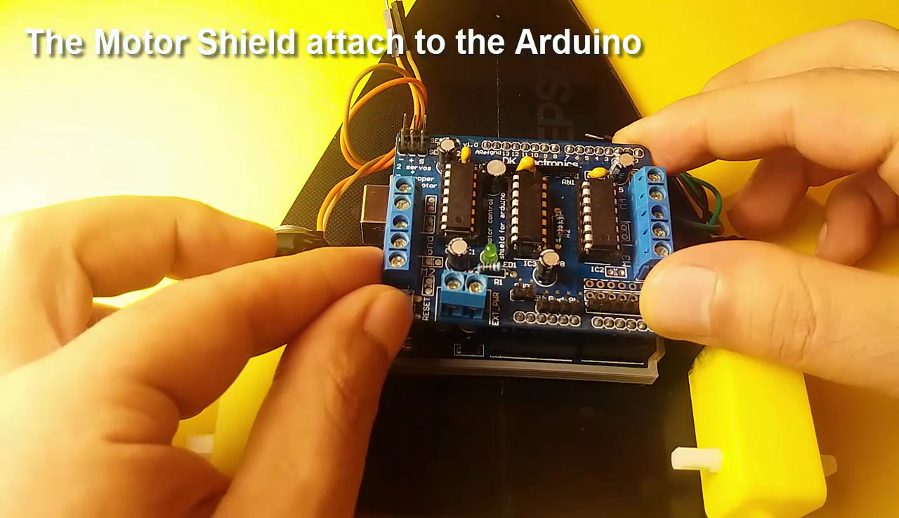
- The Motor Shield attach to the Arduino.
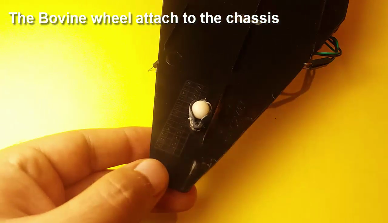
- The Bovine Wheel attach to the chassis
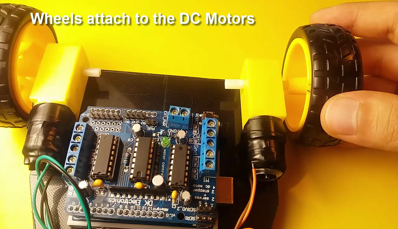
- Wheels attach to the DC Motors
About the Motor Shield
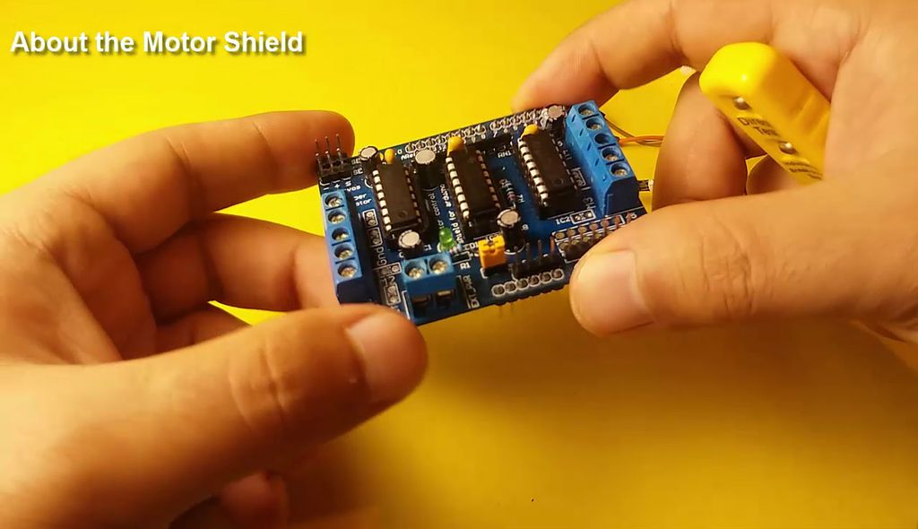
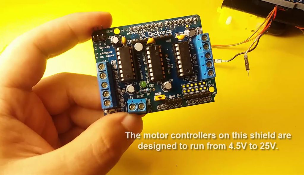
- The motor controllers on this shield are designed to run from 4.5V to 25V.
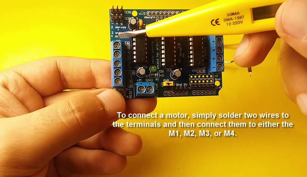
- There are two places you can get your motor 'high voltage supply' from. One is the DC jack on the Arduino board and the other is the 2-terminal block on the shield that is labeled EXT_PWR.
- To connect a motor, simply solder two wires to the terminals and then connect them to either the M1, M2, M3, or M4.
DC Motors and the QTR-8RC Sensor Connections
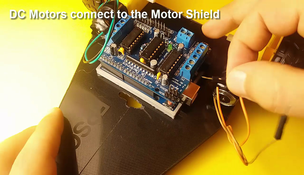
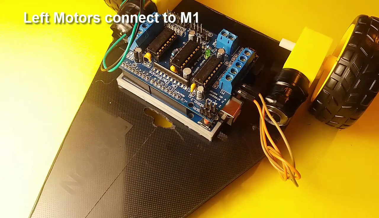
- DC Motors connect to the Motor Shield
- Left Motor connect to M1 - Right Motor connect to M2
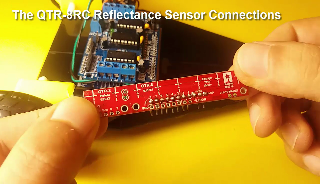
- The QTR-8RC Reflectance Sensor Connections
- The Sensor VCC connect to the Arduino +5V
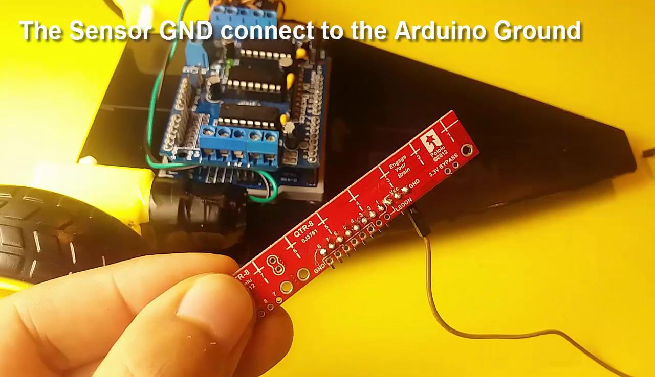
- The Sensor GND connect to the Arduino Ground
- The Sensor pin 2 connect to the Arduino Analog 0
- The Sensor pin 3 connect to the Arduino Analog 1
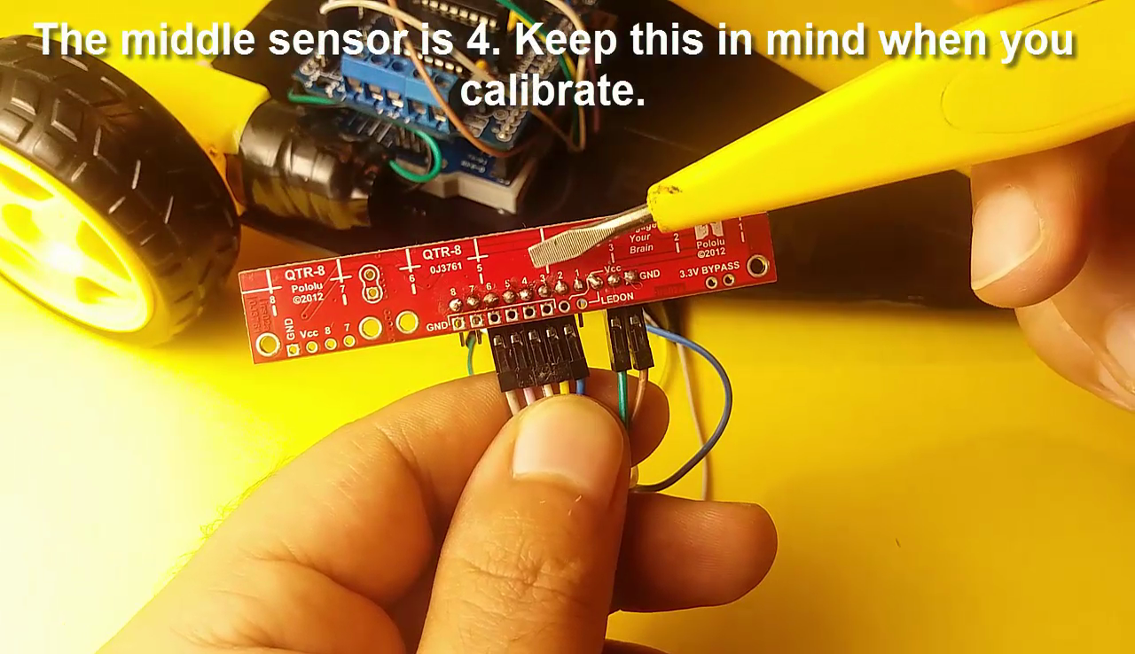
- The Sensor pin 4 connect to the Arduino Analog 2
- The Sensor pin 5 connect to the Arduino Analog 3
- The Sensor pin 6 connect to the Arduino Analog 4
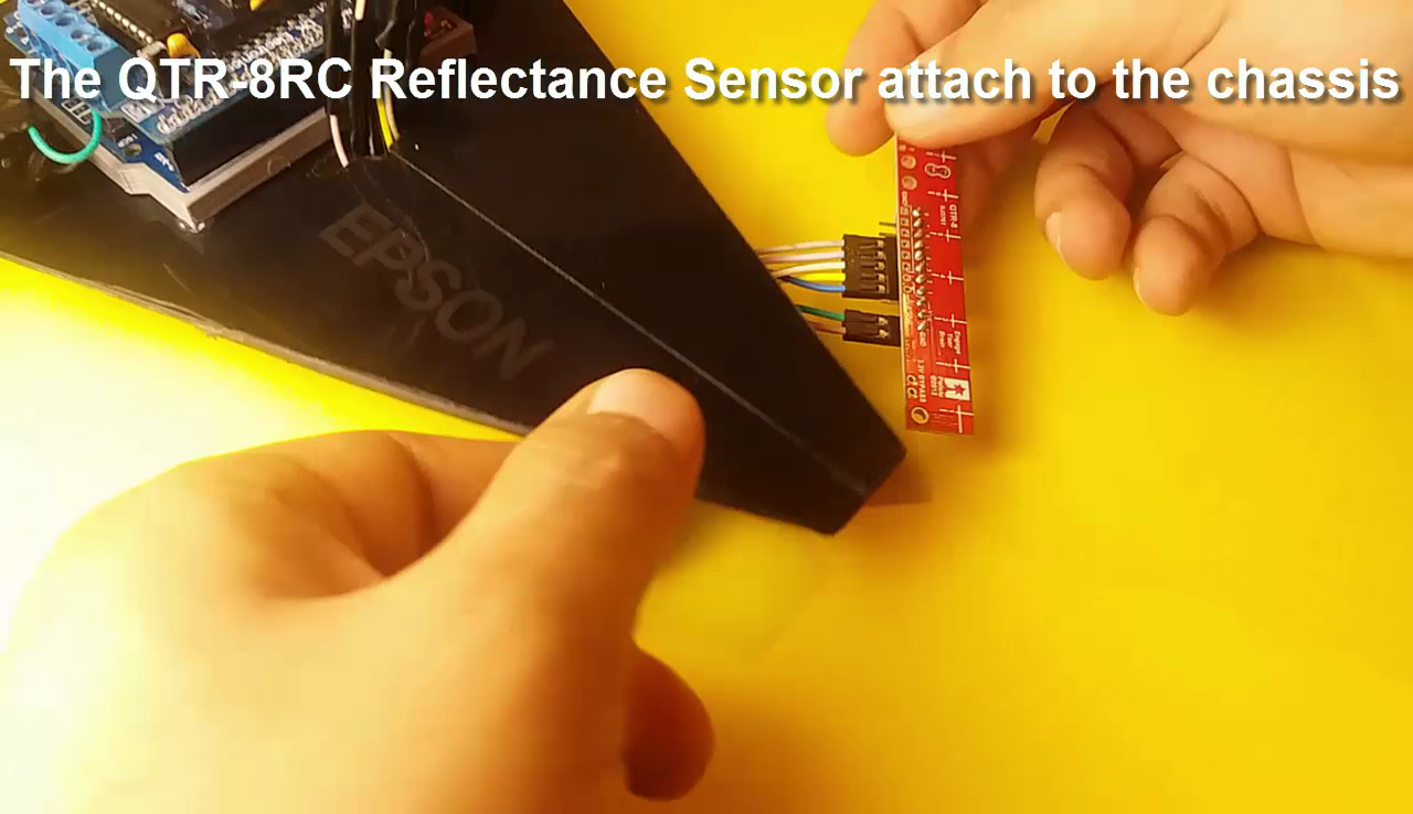
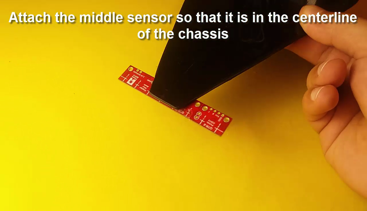
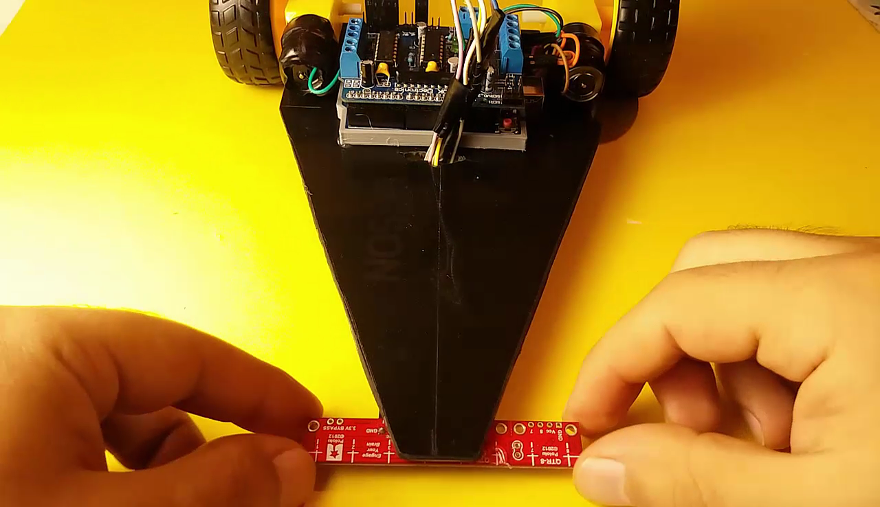
- The QTR-8RC Reflectance Sensor attach to the chassis
Battery and on / Off Button Connection
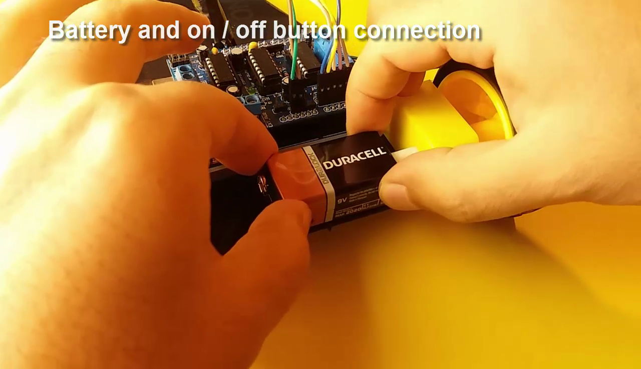
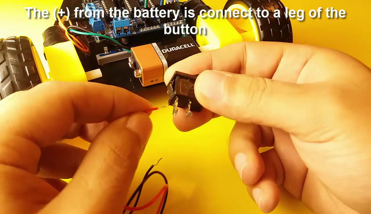
- The (+) from the battery is connect to a leg of the button
- Connect a cable to the other legs of the button. This cable is for Motor Shield (+)
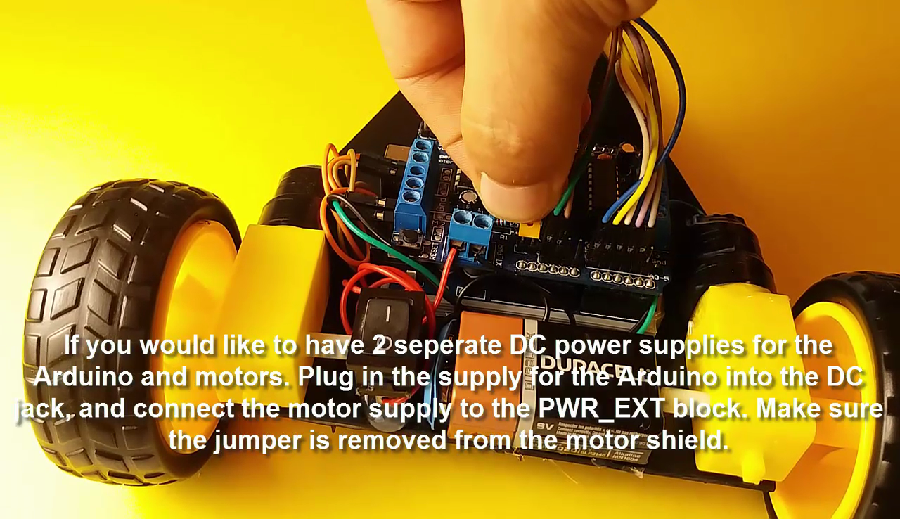
- If you would like to have 2 seperate DC power supplies for the Arduino and motors. Plug in the supply for the Arduino into the DC jack, and connect the motor supply to the PWR_EXT block. Make sure the jumper is removed from the motor shield.
Copy the Code and Install the Arduino Libraries
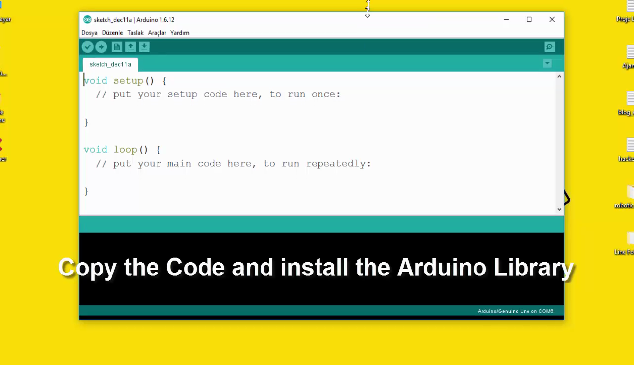
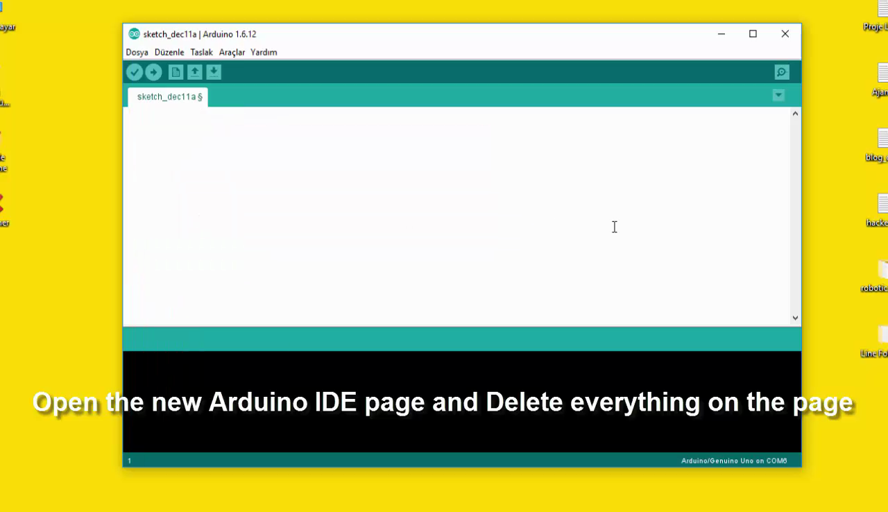


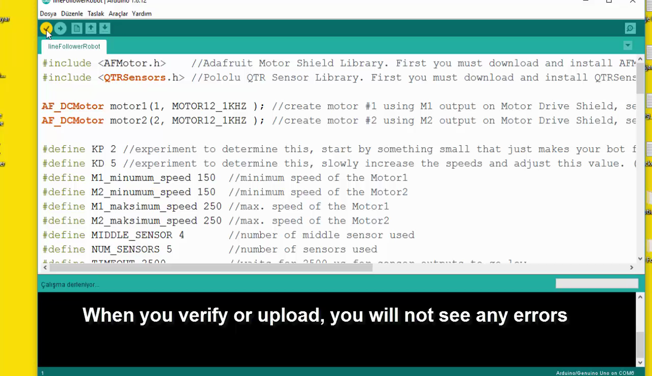
- Open the new Arduino IDE page and Delete everything on the page
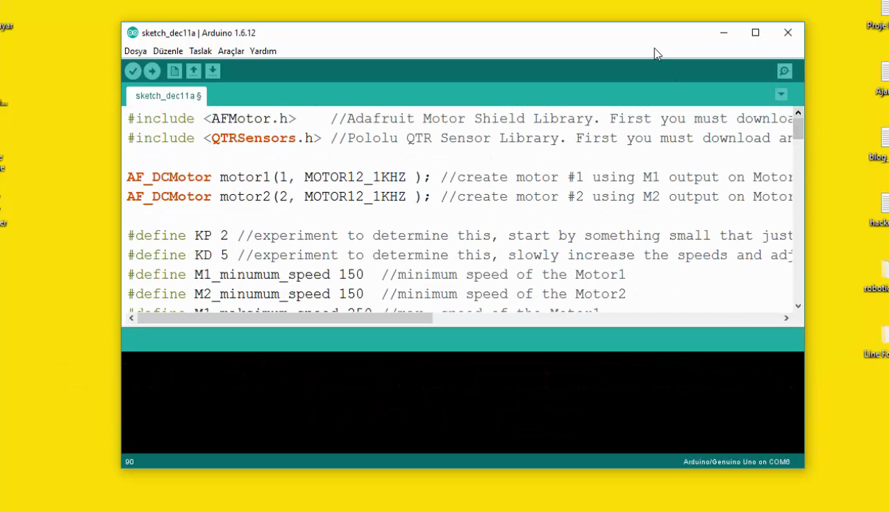
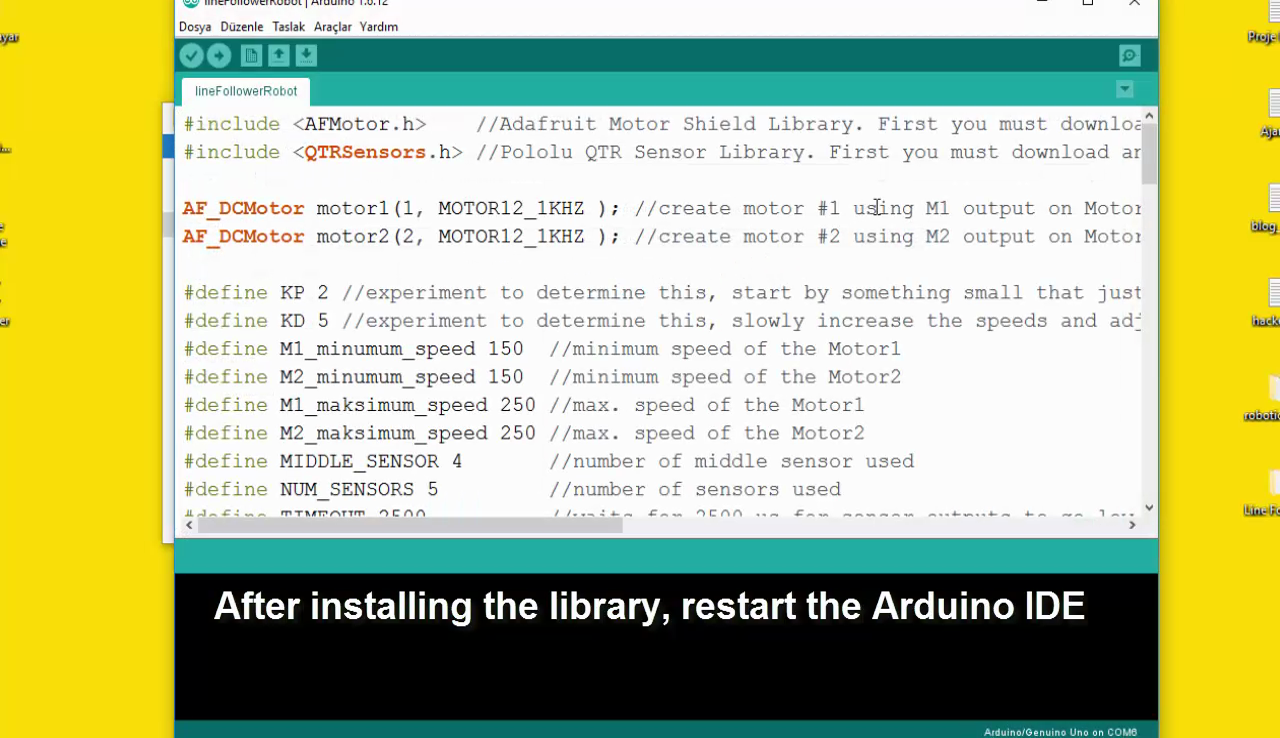
- Get the code from my blog page and Paste empty Arduino IDE page
- Get the Arduino Code in video description
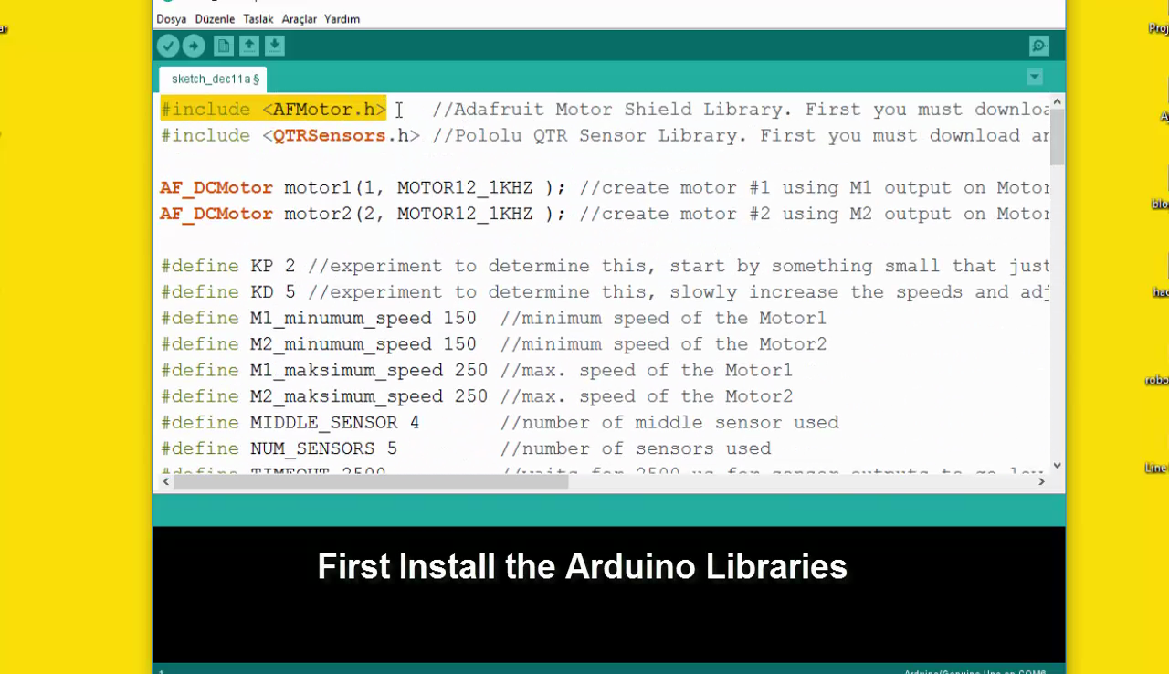
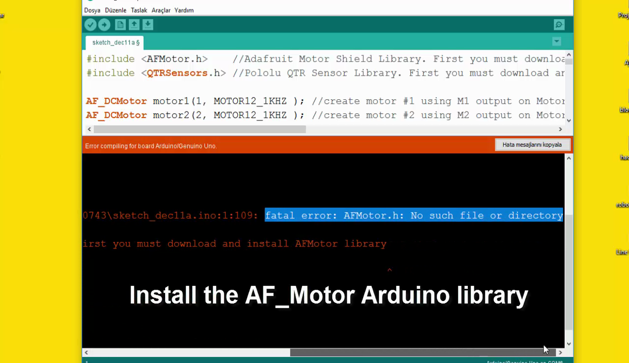
- Install the AF_Motor Arduino library
- Download the library
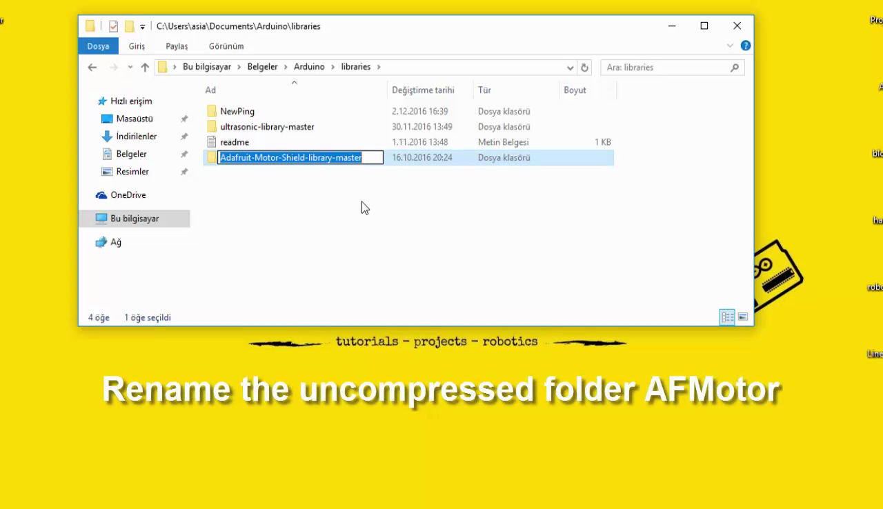
- Uncompress the ZIP file onto your desktop
- Place the AFMotor folder into your arduinosketchfolder/libraries folder
- Rename the uncompressed folder AFMotor
- Install the QTRSensors library
- Download the library
-
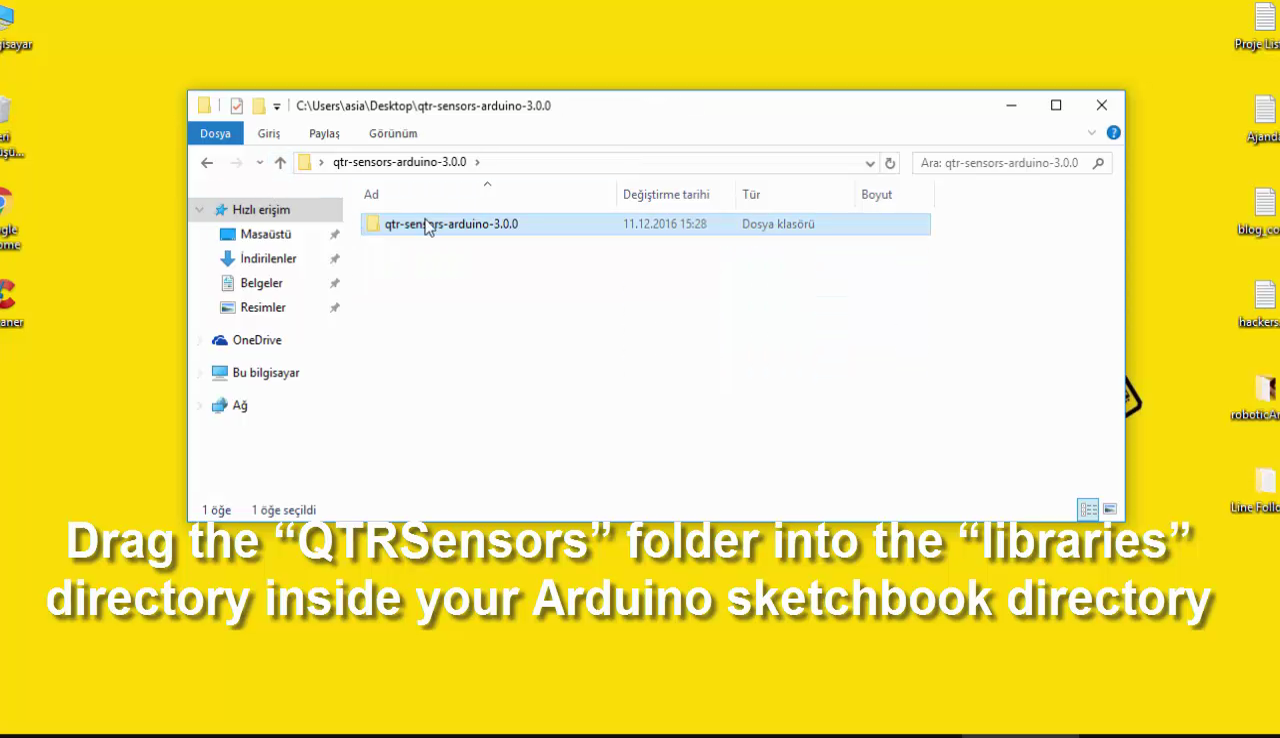
Rename the folder “qtr-sensors-arduino-xxxx” to “QTRSensors”
-
Drag the “QTRSensors” folder into the “libraries” directory inside your Arduino sketchbook directory
- After installing the library, restart the Arduino IDE
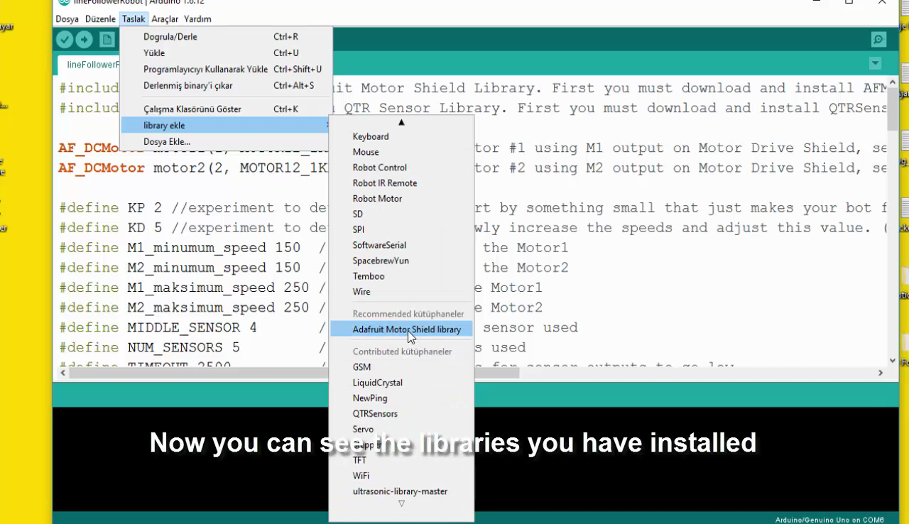
- Now you can see the libraries you have installed
-
When you verify, you will not see any errors
If It Helps, Please Subscribe

First of all, I would like to thank you for reading this guide ! I hope it helps you.
If you want to support me, you can subscribe my channel and watch my videos.