Arduino Light Switch Flipper W/ IR Remote
by al5259 in Circuits > Arduino
1175 Views, 0 Favorites, 0 Comments
Arduino Light Switch Flipper W/ IR Remote
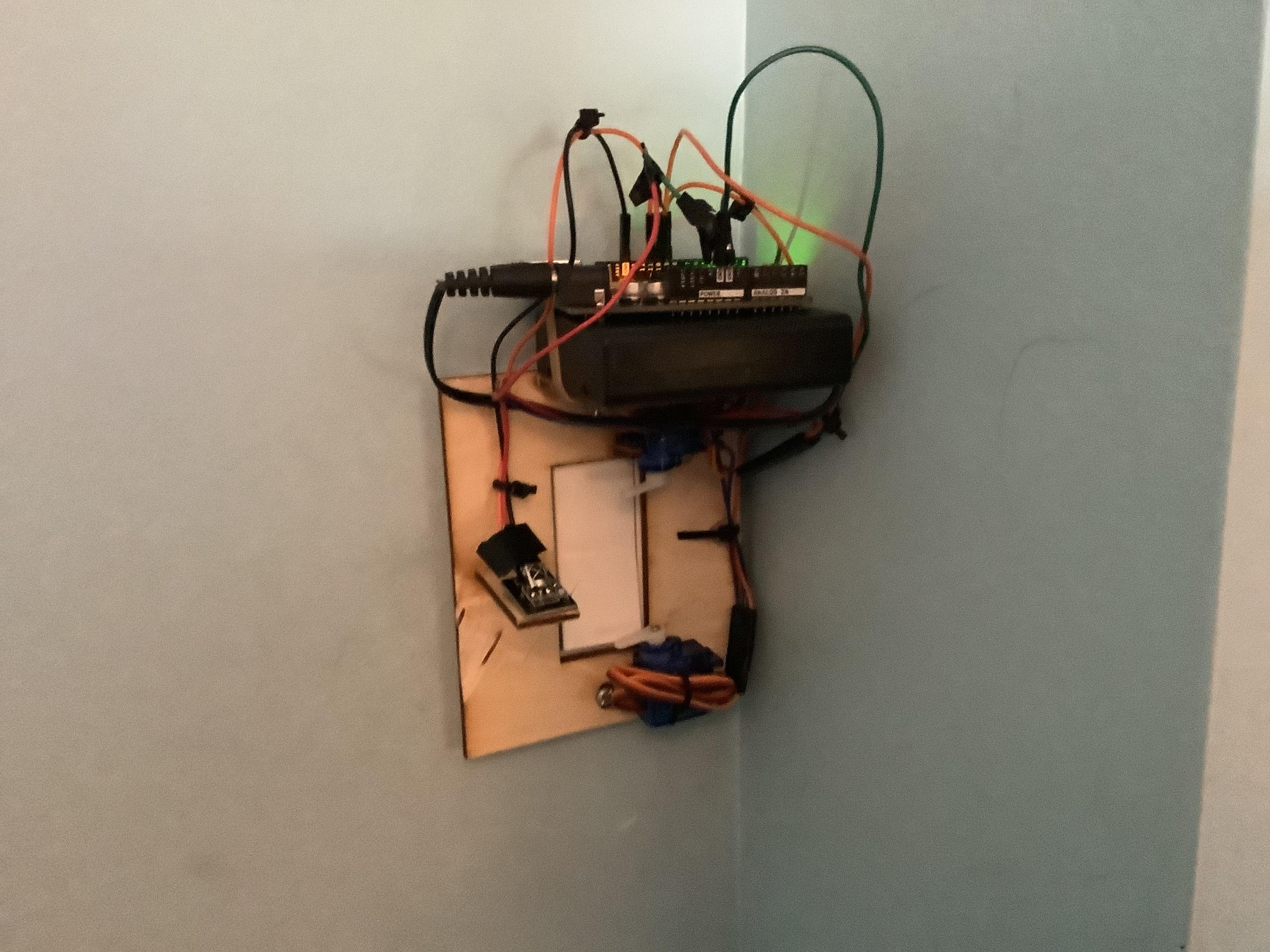
This uses servos to flip a light switch. I made it so you can flip a light switch from two places instead of one.
Supplies
Suggested: Elegoo Super Starter Kit, gives you most of the required electronics, all you need is extra servo, AA battery case, and maybe some wires
Arduino UNO
x2 SG90 Servos
Elegoo IR Remote & Receiver (non elegoo remote might use different hex codes so you would have to find those)
AA Battery Case with x4 AA Batteries
Few jumper wires, M-M Dupont Wires, M-F Dupont Wires
1/8” thick Plywood
2x 6-32 screws
Rubber band or Tape
Hot Glue Gun
Wood Glue
Soldering Iron
Jigsaw, Coping saw or Laser Cutter (some way to cut the wood, I used laser cutter but these also work)
Coding the Arduino
.png)
.png)
.png)
- Make sure you have the Arduino IDE installed and set up. You can download it here https://www.arduino.cc/en/software
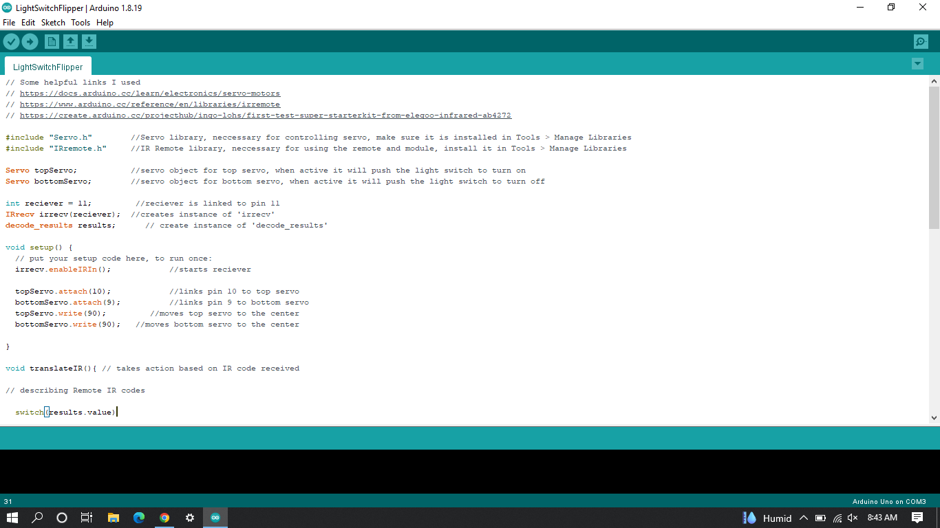
- Download the .ino file containing the code for this project. Most of the code is explained in comments. To open it in Arduino IDE, it will likely ask you to put it in a sketch folder. Let it do this.
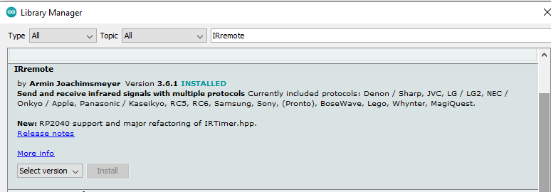
- Download the servo and IRremote libraries from the Library Manager in the Arduino IDE. It can be found under the Tools menu.
- If you have trouble with servos or the IR receiver, make sure to check the lines I put at the top. These also contain different hex codes if you want to change which buttons you want to use.
- Click upload to send it to the Arduino, make sure it is plugged in and the right USB port is selected.
Downloads
Wiring
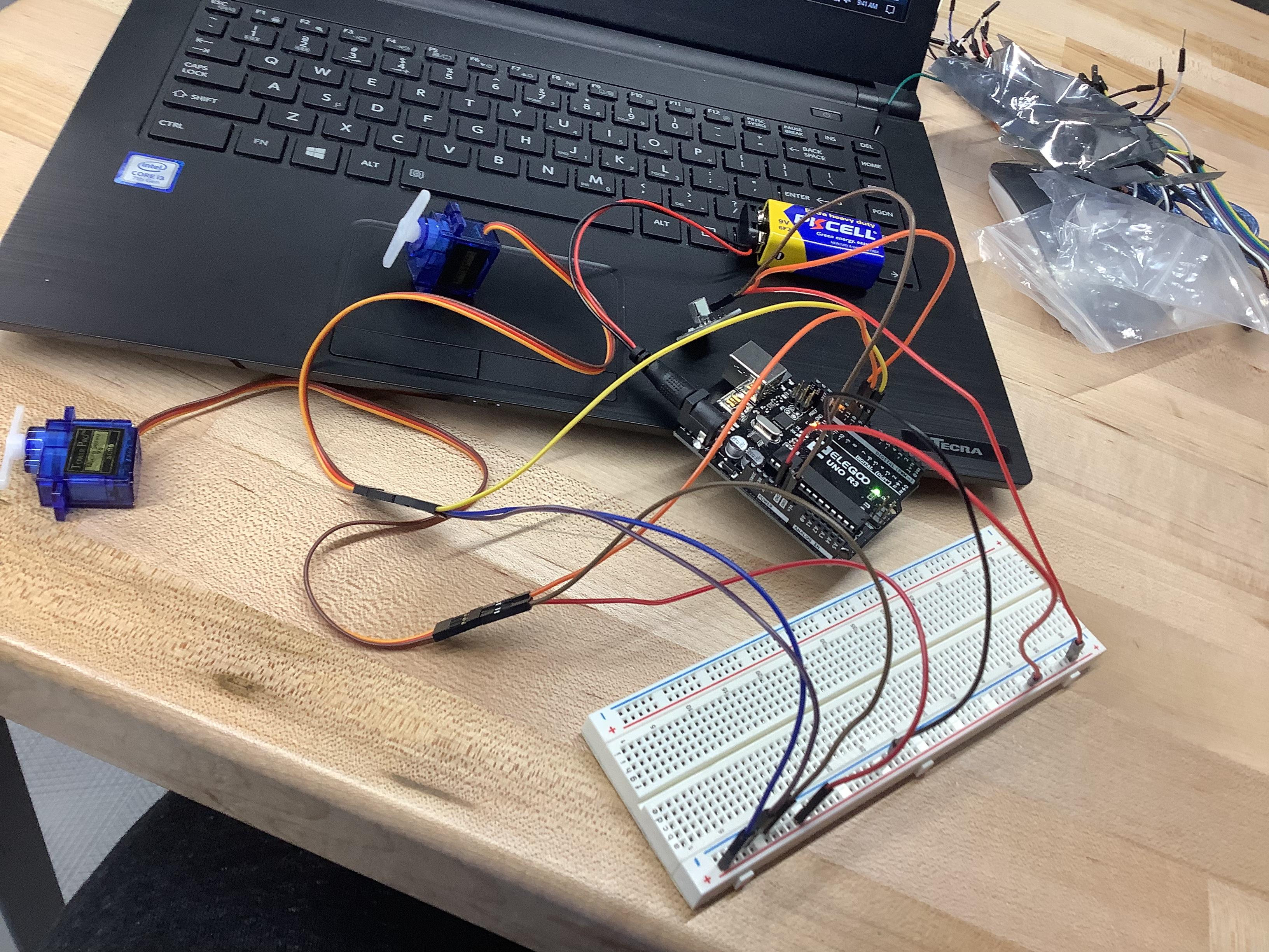
Test it out by wiring it on a breadboard first.
- Plug GND and 5V into the breadboard first.
- GND goes to Servos darkest wire (brown or black)
- Power goes to Servos red wire.
- Pin 9 on Arduino goes to Bottom Servo signal wire (usually white or orange)
- Pin 10 on Arduino goes to Top Servo signal wire (usually white or orange)
- Pin 11 on Arduino goes to IR receiver signal wire (make sure to find out how to wire IR receiver)
- Power and Ground the IR receiver (make sure to find out how to wire IR receiver)
Confirm it works by pressing the Up/Down buttons on the IR remote.
Once it works, wire everything but the power wires directly to the Arduino. There are three GND pins on the Arduino which can all be used. Because there is only one 5V pin on the Arduino, you have to use either a mini breadboard, a shield, or solder four wires together. I chose to solder them, make sure that one of the wires fits the IR receiver. If you choose a mini breadboard, make sure it fits on top of the Arduino.
Designing the Frame
.png)
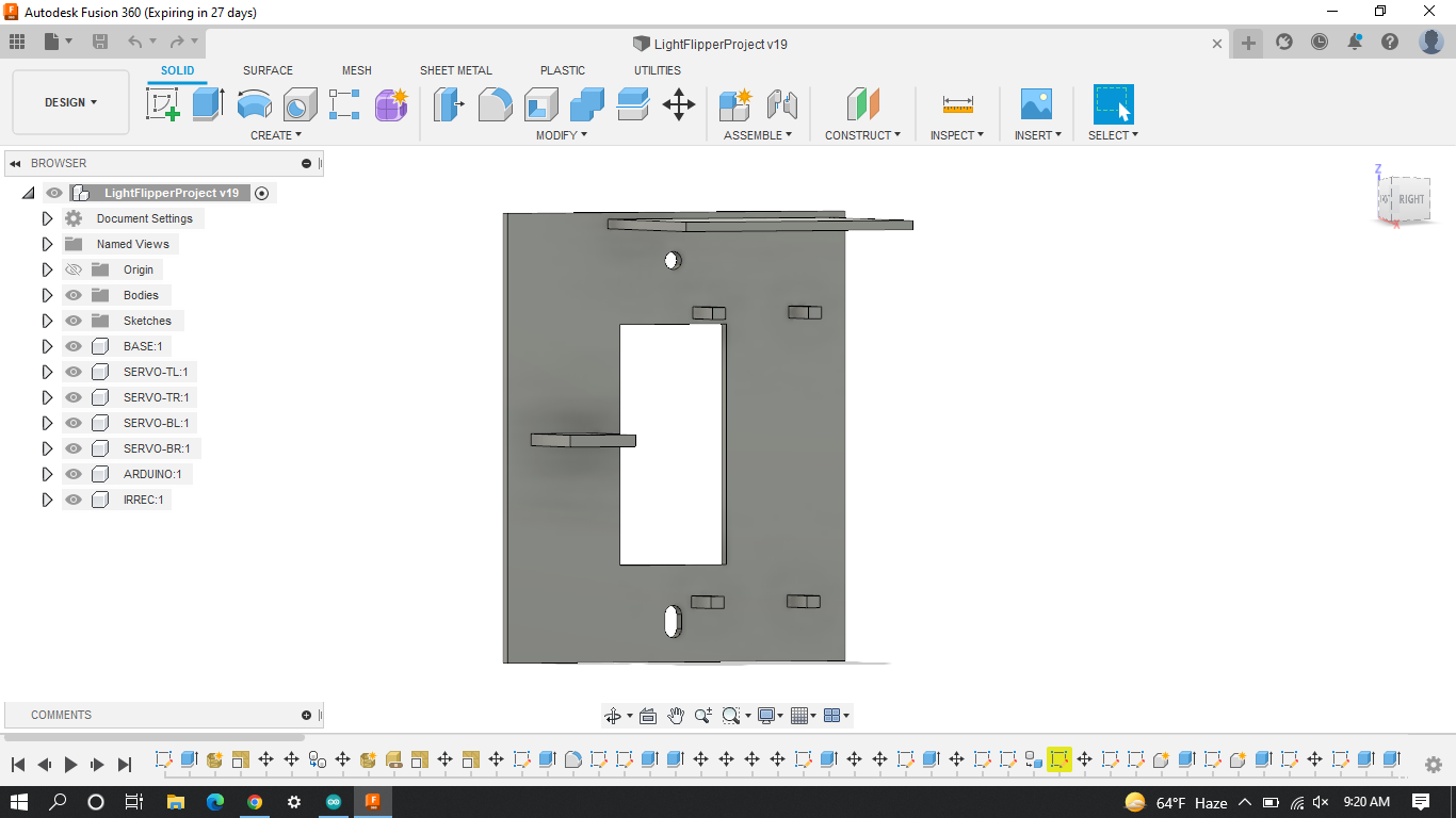
For the frame, I used the two screws that go above and below a light switch. I measured the holes for the screws and the hole for the light switch. I then created it in Fusion 360. For the servos, I used two arms to hold each one up. I extended the bottom hole so it would be easier to fit the screw and still keep the frame from moving left/right. I added in a plate for the IR reciever and battery case, which the Arduino sits on. I attached my fusion file below if you want to modify it.
Downloads
Creating the Frame - Cutting
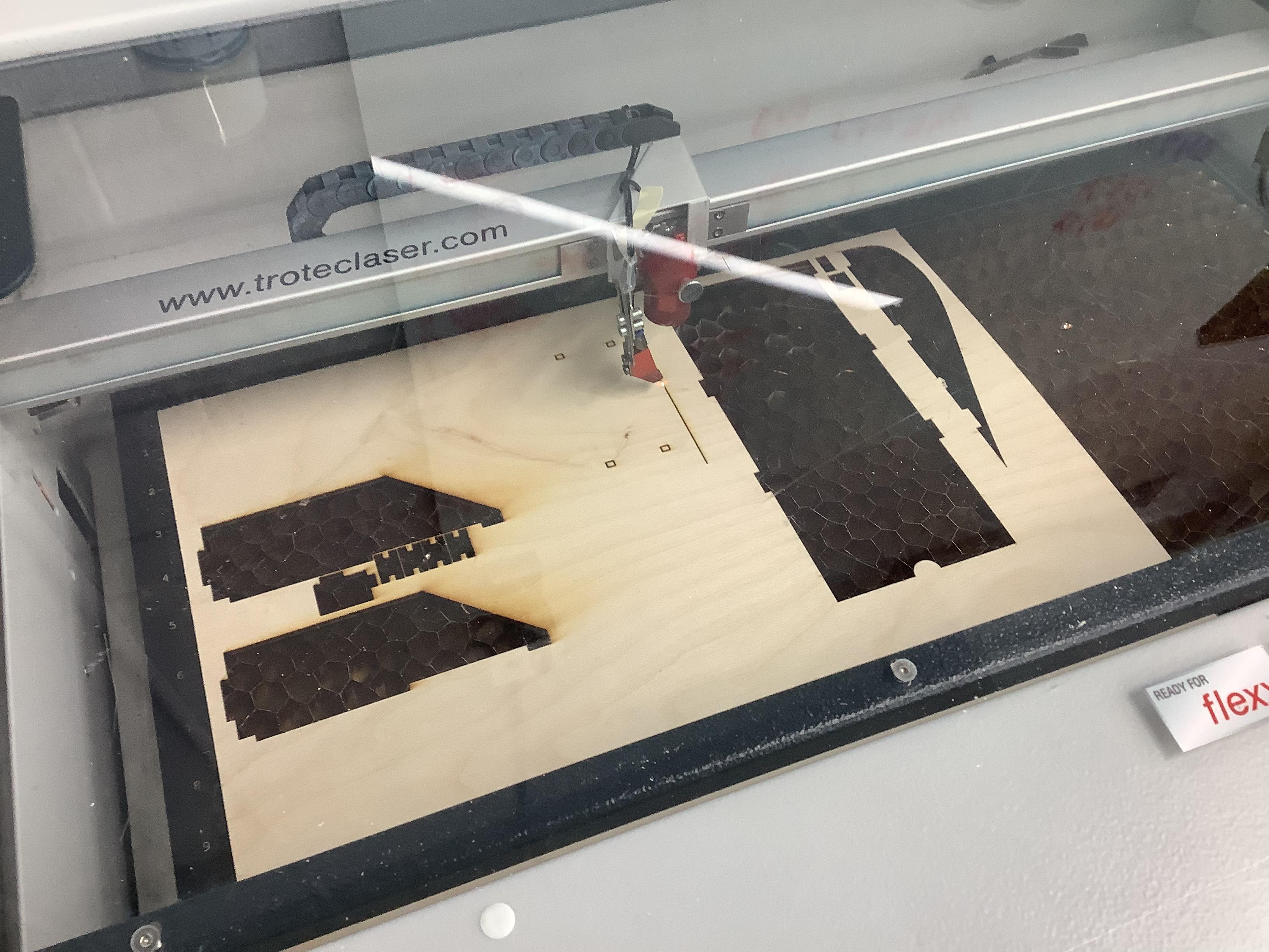
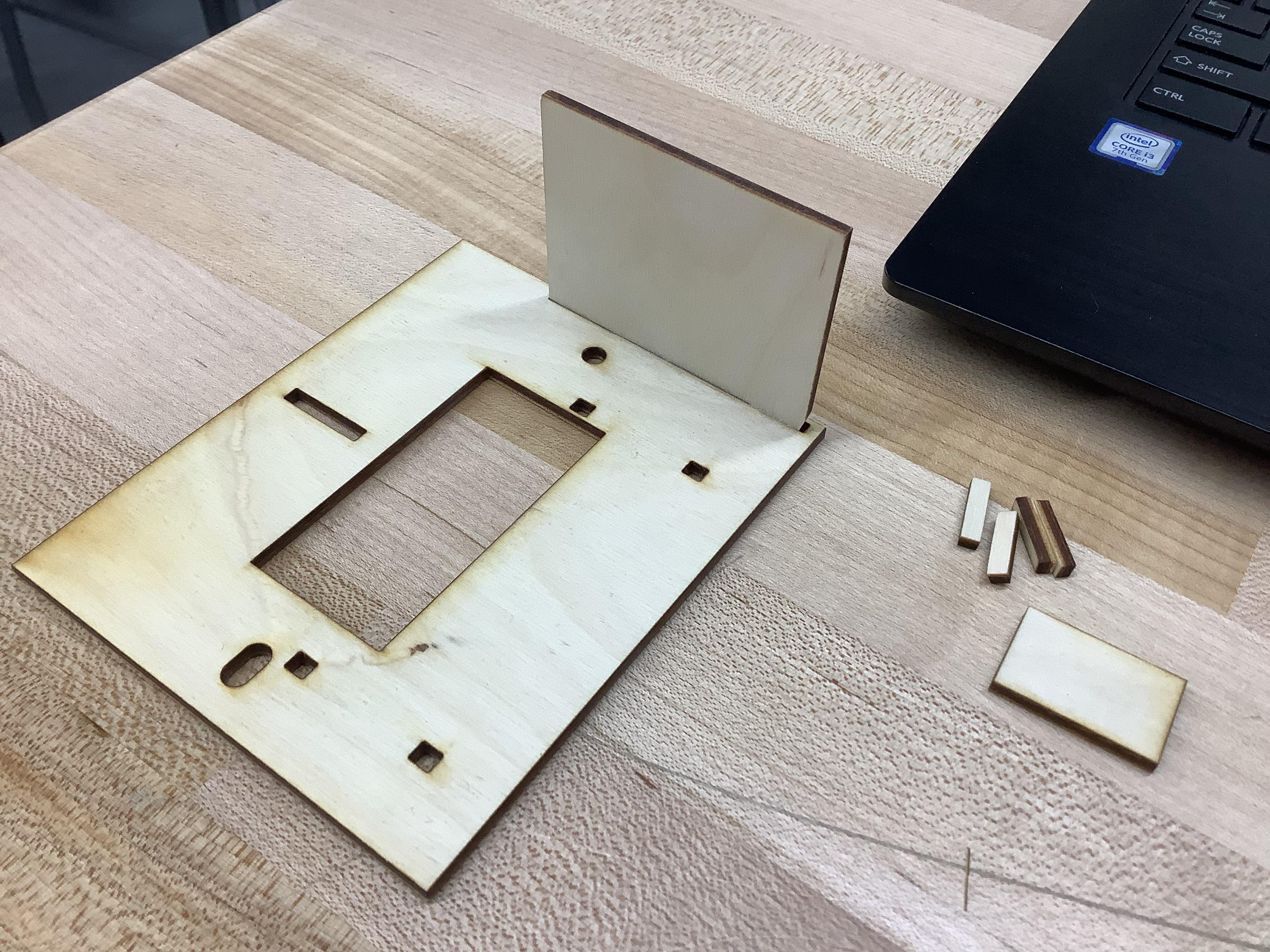
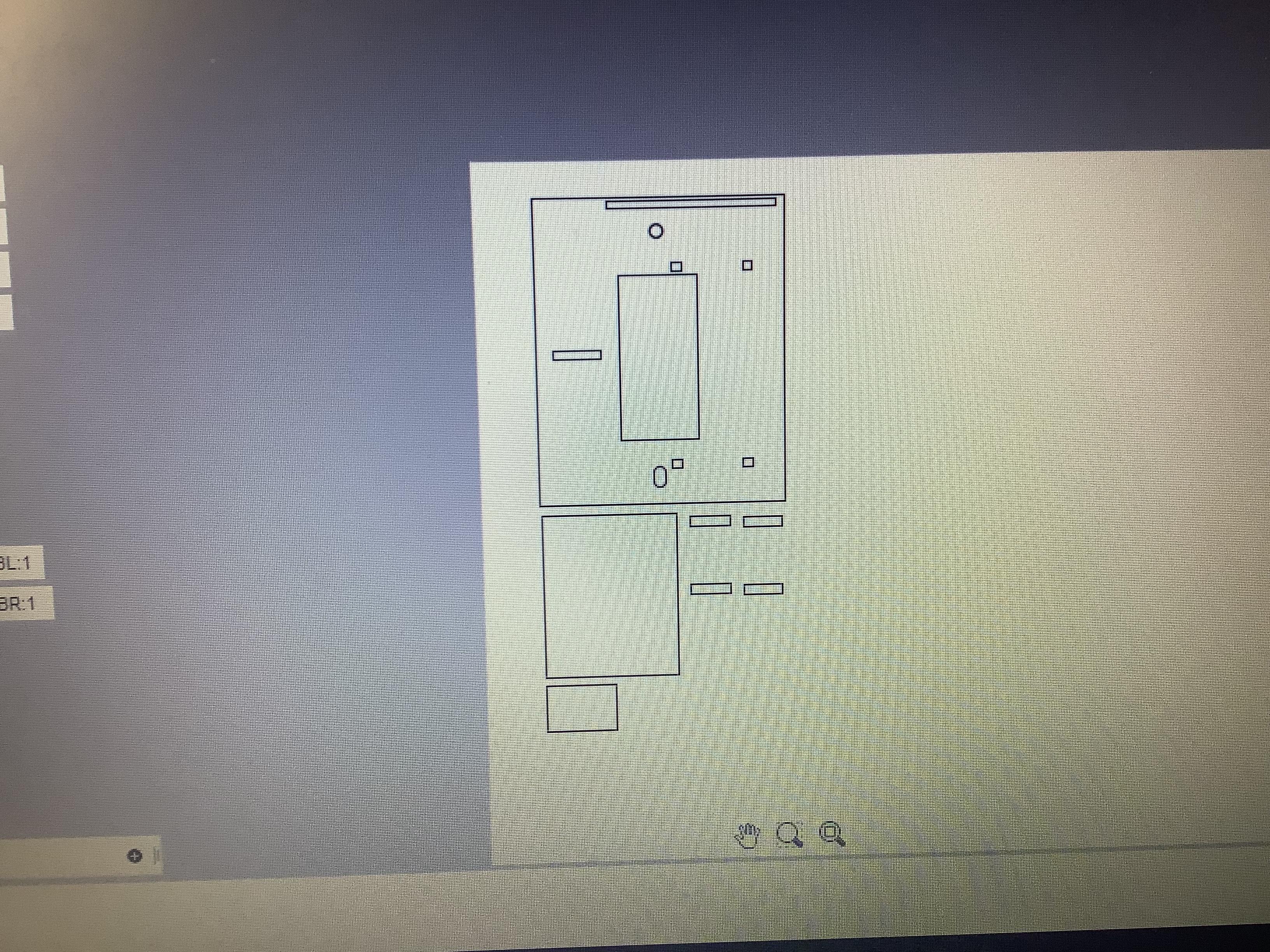
This is where the plywood and cutting comes in. I used a laser cutter but as long as you have a saw that can make a cut on the inside of something like a jigsaw or coping saw will work.
Way 1 - Laser Cutter
Use the attached SVG and upload it to the laser cutter. If you need a different file format or some other
way, you can get the fusion file in the step above and export it that way.
Way 2 - Cutting With A Saw
Use the attached PDF or SVG file and print it out to use as a template. Instead of using those tiny arms,
you can use skewers and drill a small circular hole in the place of those. Cut out all the pieces and move
on to the next step.
Creating the Frame - Gluing
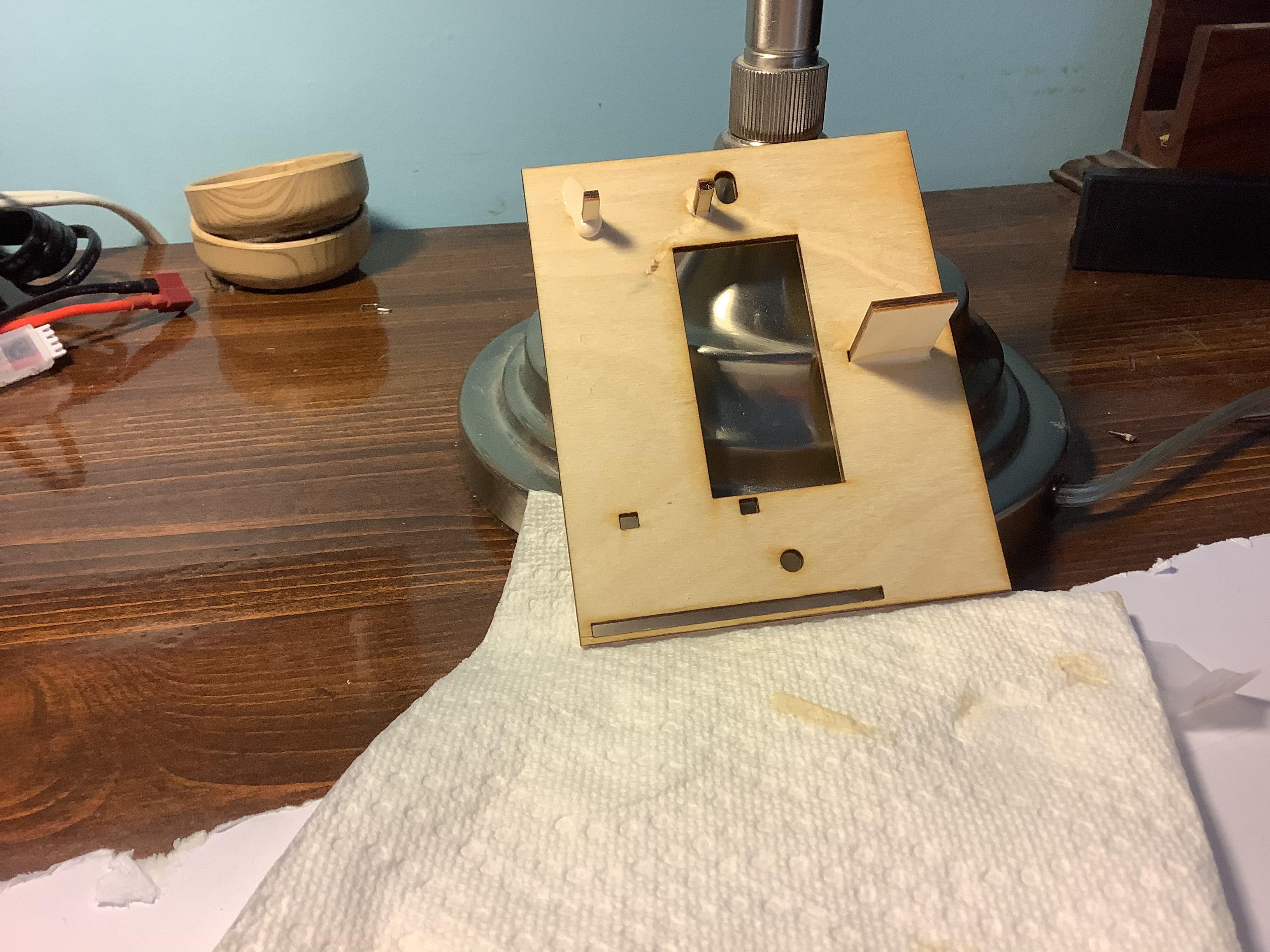
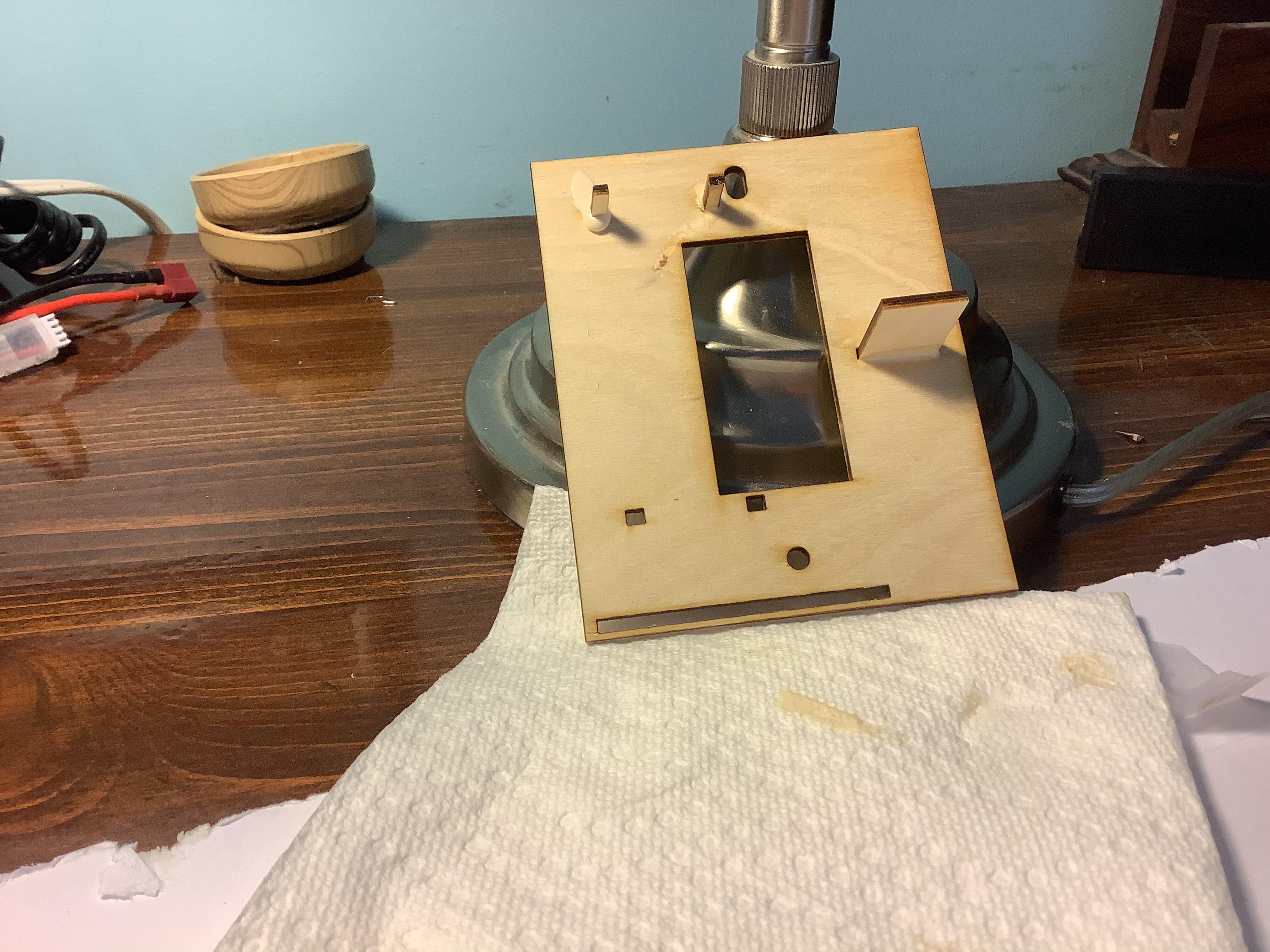
For this step you need wood glue and the parts from the previous step. I used some Elmer's Wood Glue Max but you could probably use most wood glues. Make sure all the components fit and won't fall off before gluing the wood parts. Glue in all of the plates and arms into place. Cut the skewers to a good size if you are using them, enough to hold the servo.
Gluing Components
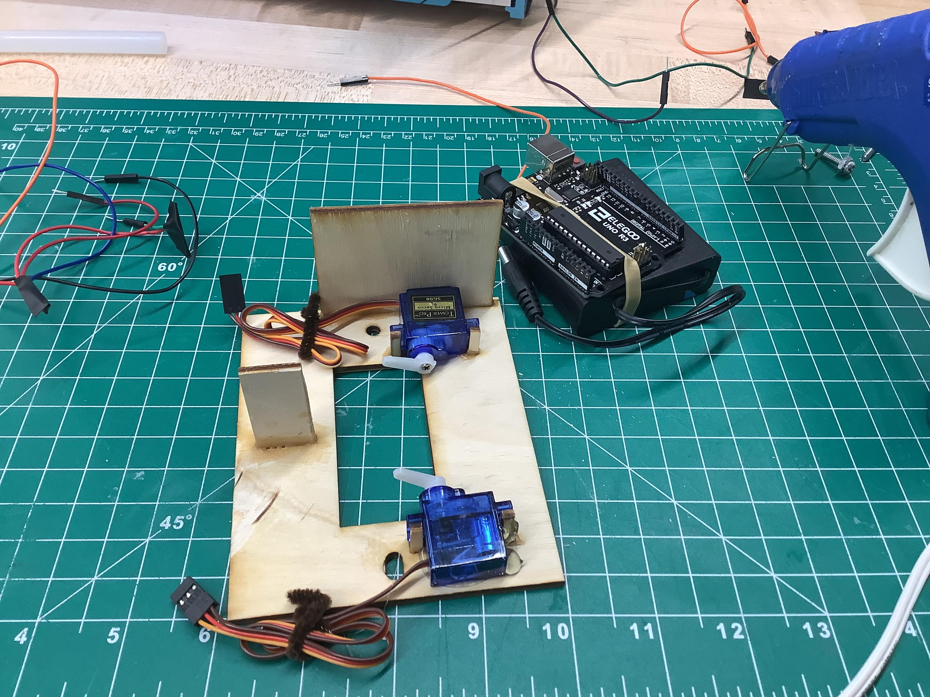
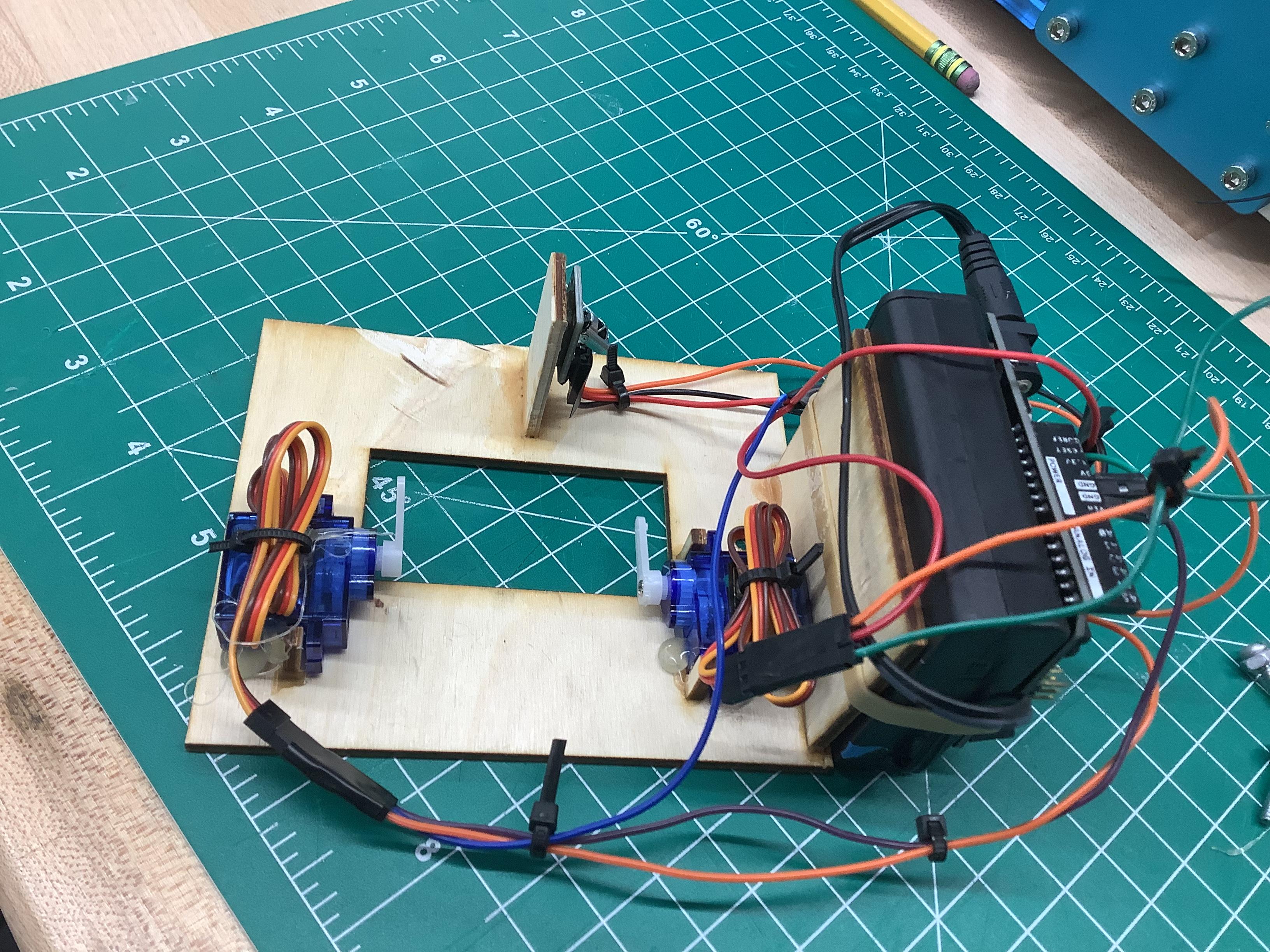
Important: Before hot gluing servos, make sure to tape them to the plate first and find out a good position to the servo arm and screw it in. It's hard to get a screwdriver in there once you have glued it. Make sure you can actually screw the entire frame to the switch as well.
Also Important: Wire the IR receiver before gluing it, the dupont wires can be tough to fit when you do.
In this step, use some hot glue to glue the components to the plate. I didn't hot glue the Arduino and battery case since I will probably be using it for other projects, however you should definitely hot glue the servos, otherwise they get pushed away when flipping the light switch. The IR receiver should also be hot glue since it is hard to tape it without actually covering the receiver.
Now, use some cable ties and glue to organizes all the wires a bit better. Attach it using the screws and now you can flip a light switch with a remote.