Arduino Light Intensity Lamp

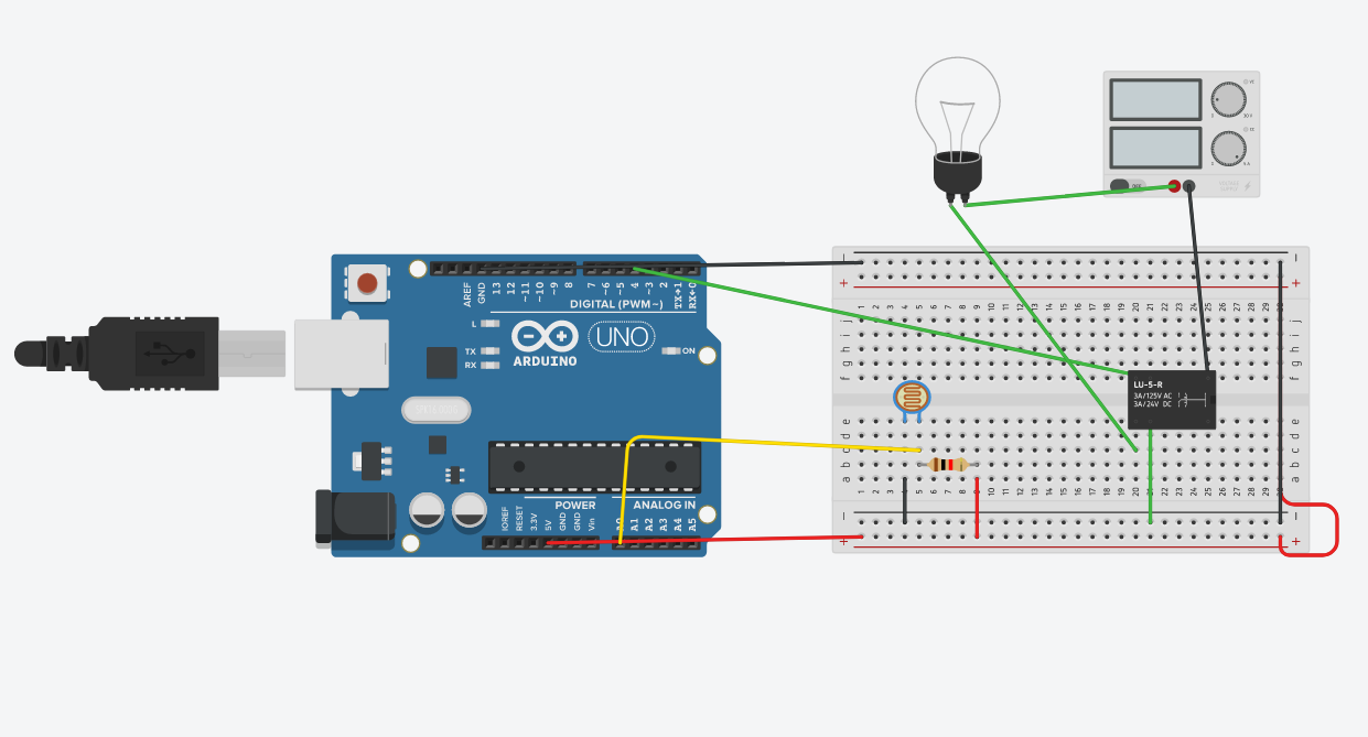
Hello, I'm Robin and I'm a student at JASS. Today I'll be discussing about how to create a Arduino Light Intensity Lamp. The following visual was made on tinker-cad since access to physical breadboards and circuits are gone because of quarantine. Tinker-cad is a very good alternative to create a good circuit and is very similar to a physical circuit being created.
Supplies
Firstly you'll need these supplies open up on Tinker-cad.
-Standard lightbulb
-Wires of different color
-Relay SDPT
-Arduino UNO R3
-Photo-resistor
- Power supply (5 voltage, 5 current)
-Breadboard (any size, smaller is more easier to navigate)
How to Actually Create the Circuit in Tinker-Cad

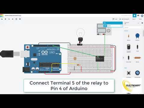
A really great visual video for creating the circuit on Tinker-cad is found on this page.
Coding

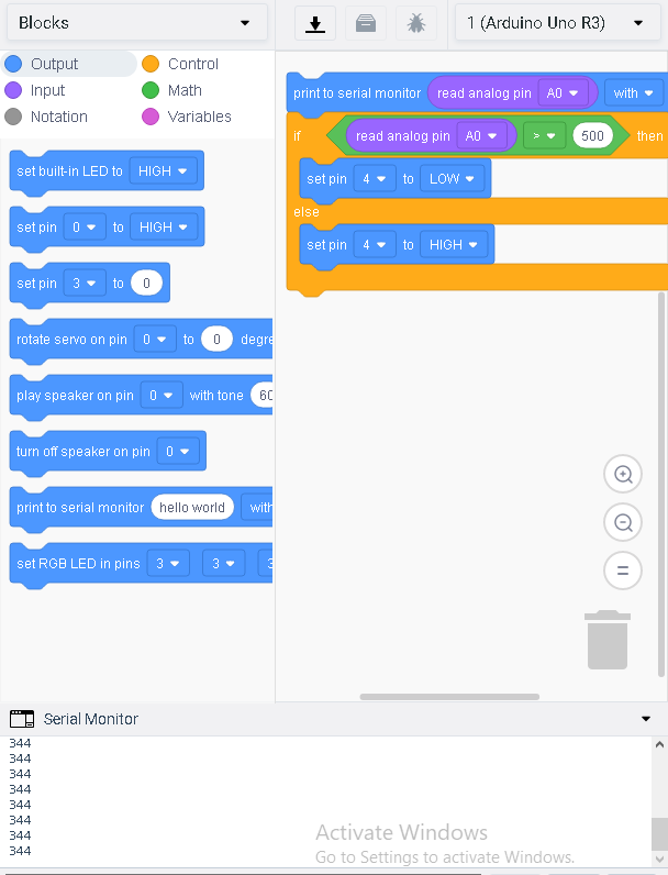
This visual above is the final product of how the circuit's code is suppose to be written. If you open up Tinker-cad's coding at first there's a pile of code you can delete and create. You want to start by clicking on the "output" tab and select the "print to serial monitor". Then you have to go to the "input" tab and select the read analog pin A0. Make sure the correct value is A0 and drag and drop into the output block. After that proceed to the "control" tab and select the "if___ then__ else" block. Refer to the visual if confused. Once found drag and drop. Lastly you'll need to go back to the input tab and select the "set pin" block. Make sure the value inside is 4 since that's the pin that's going to be doing the work. After that you can experiment as you like and run simulation and make further changes.
- Key tip: make sure your control block's first part is filled with the proper tiles in the visual above. If you'd like you can experiment with those values too.