Arduino Leonardo LED Color Changing
by ulandachen0509 in Circuits > Arduino
148 Views, 0 Favorites, 0 Comments
Arduino Leonardo LED Color Changing
The lightbox can be used for many functions, for example, the lights' colors can be adjusted and be used as a lamp. As the potentiometer is being turned, different LED lights with different colors light up.
Materials
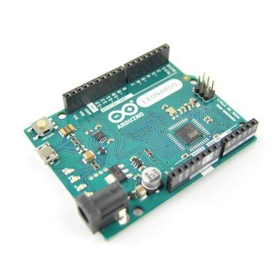
- Arduino Leonardo x1
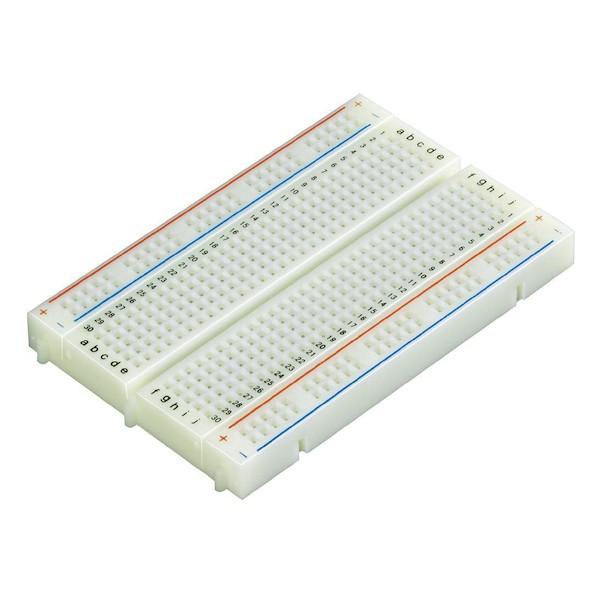
- Breadboard x1
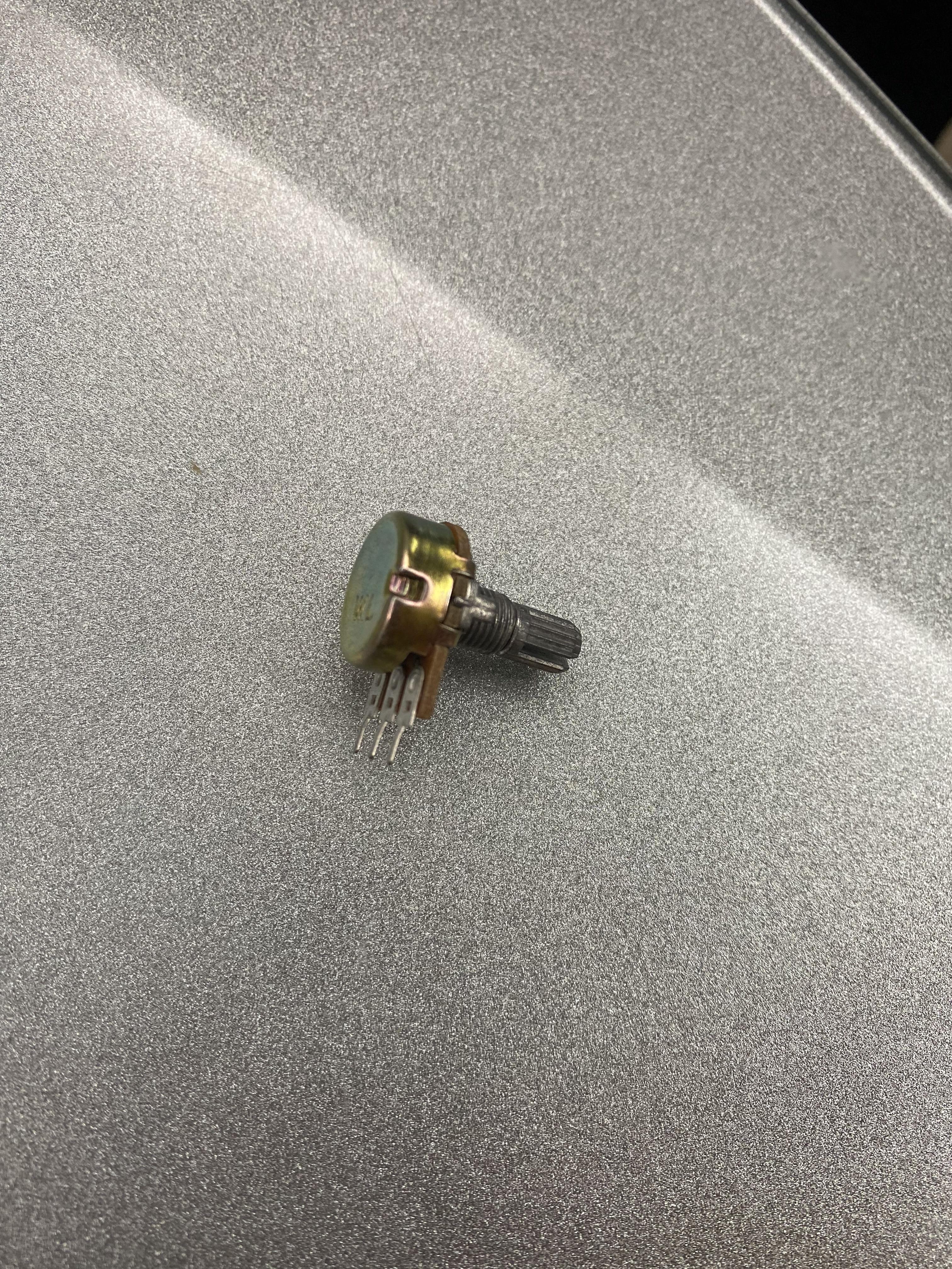
- Potentiometer x1
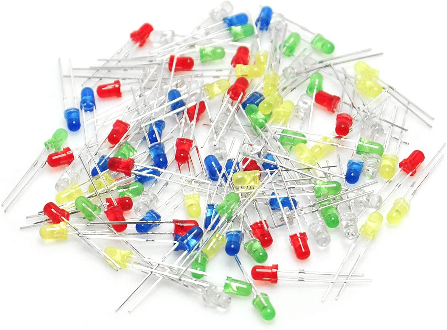
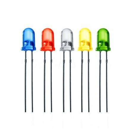
- 3mm LED x5 (red, yellow, blue, green, white)
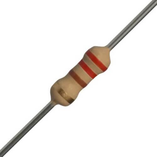
- 220-ohm Resistor x5
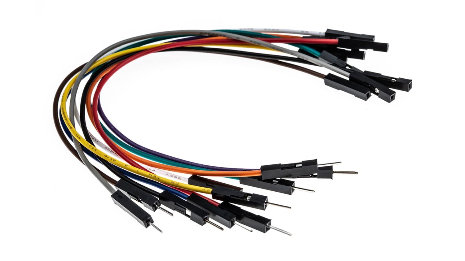
- Jumper Wires x15 (male-male x10, male-female x5)
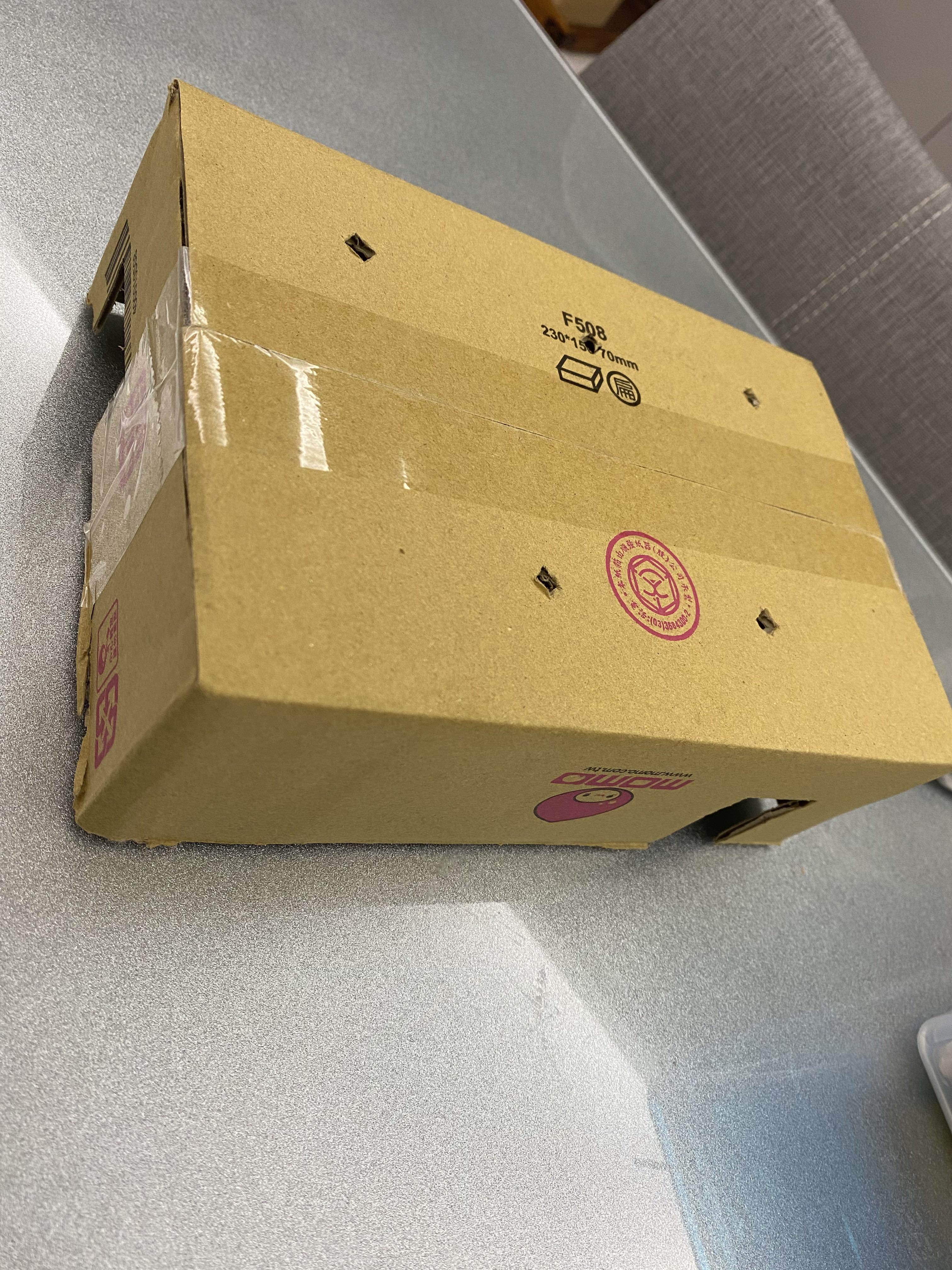
- Box x1
- Tape x1
Procedure
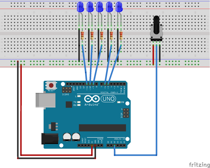
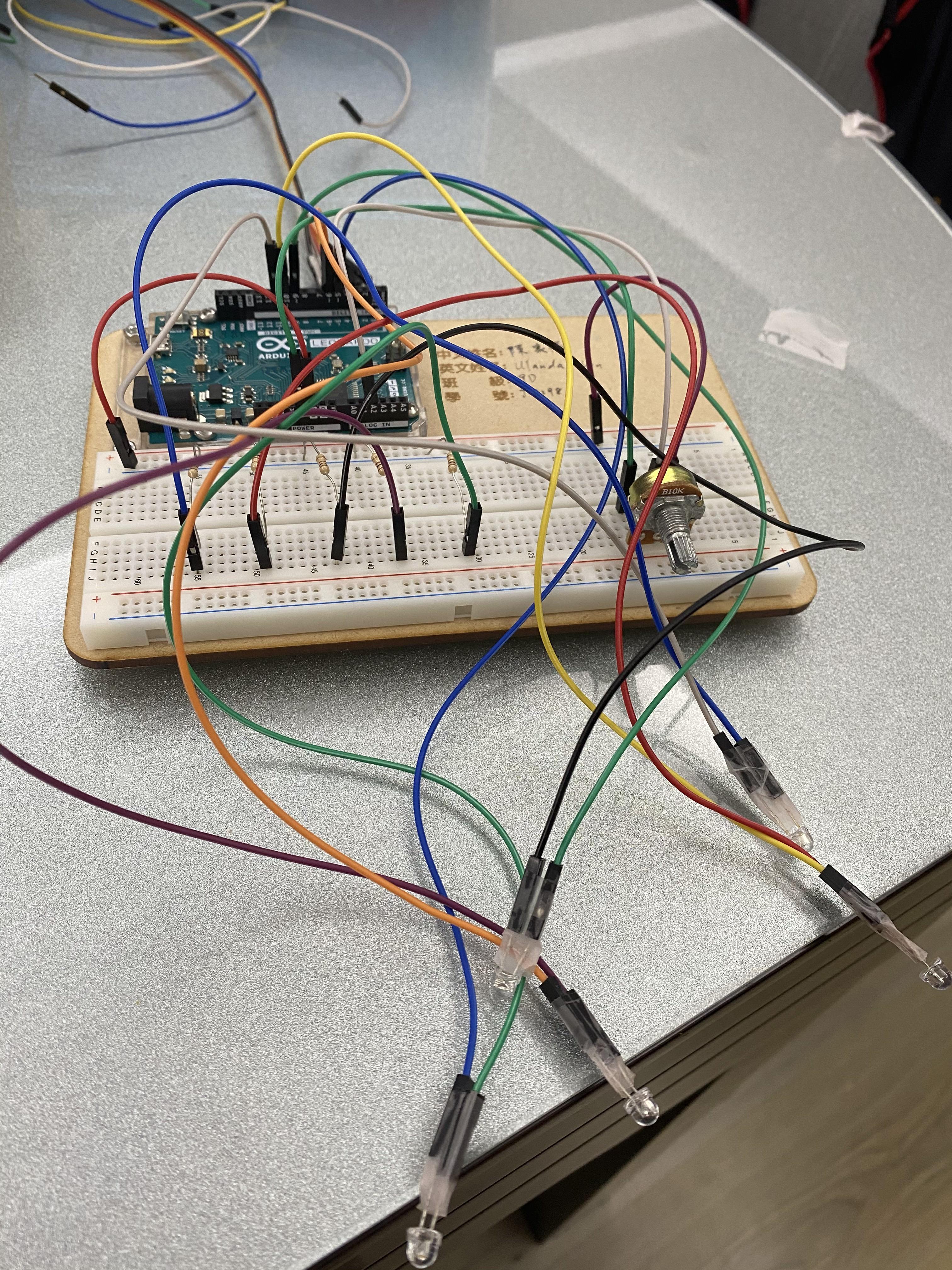
- Connect the circuit according to the picture above. *Use male-female wires for the LED
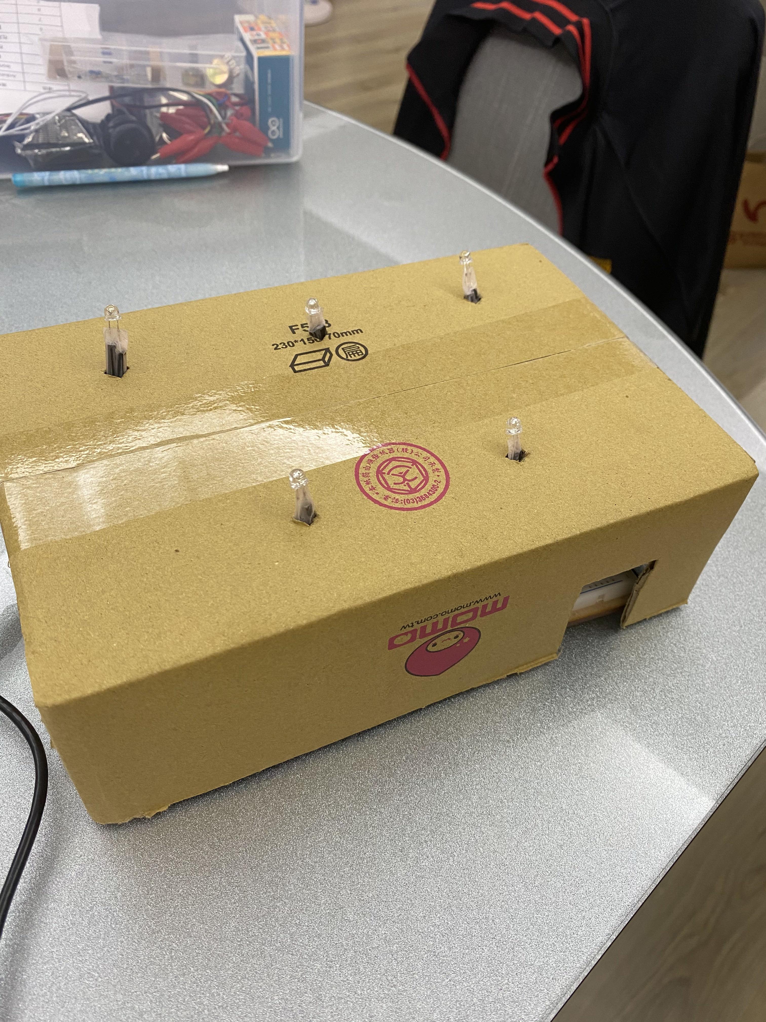
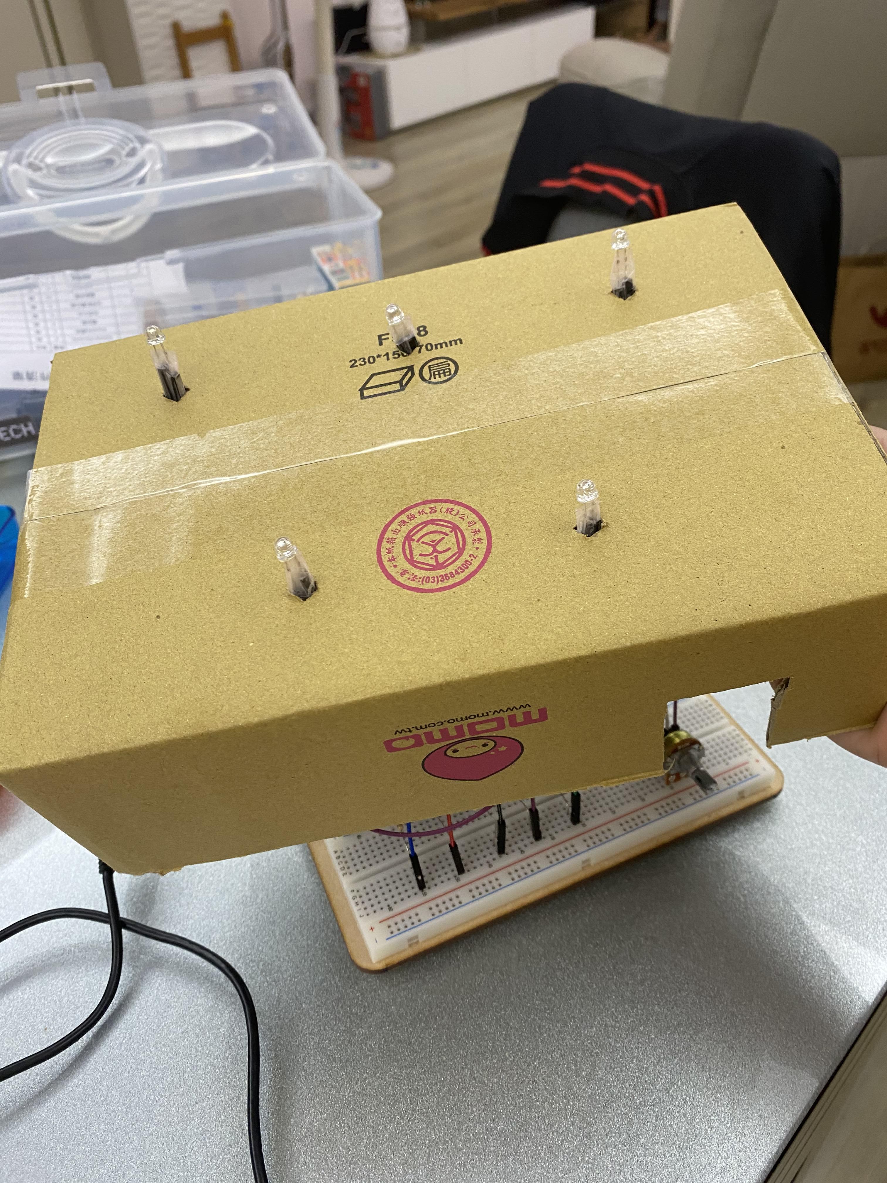
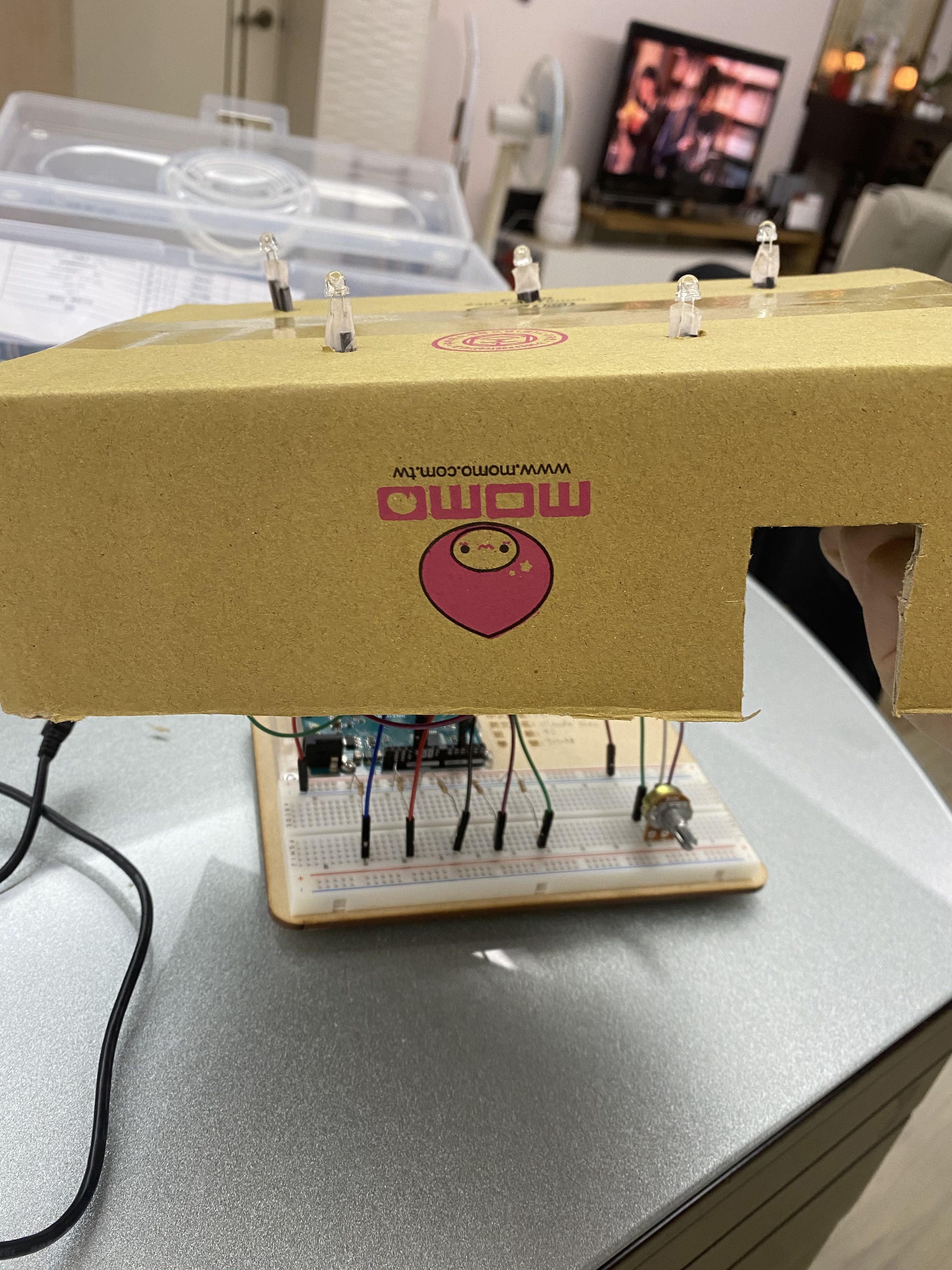
- Make the box
- Cut five small holes on top of the box for the LED
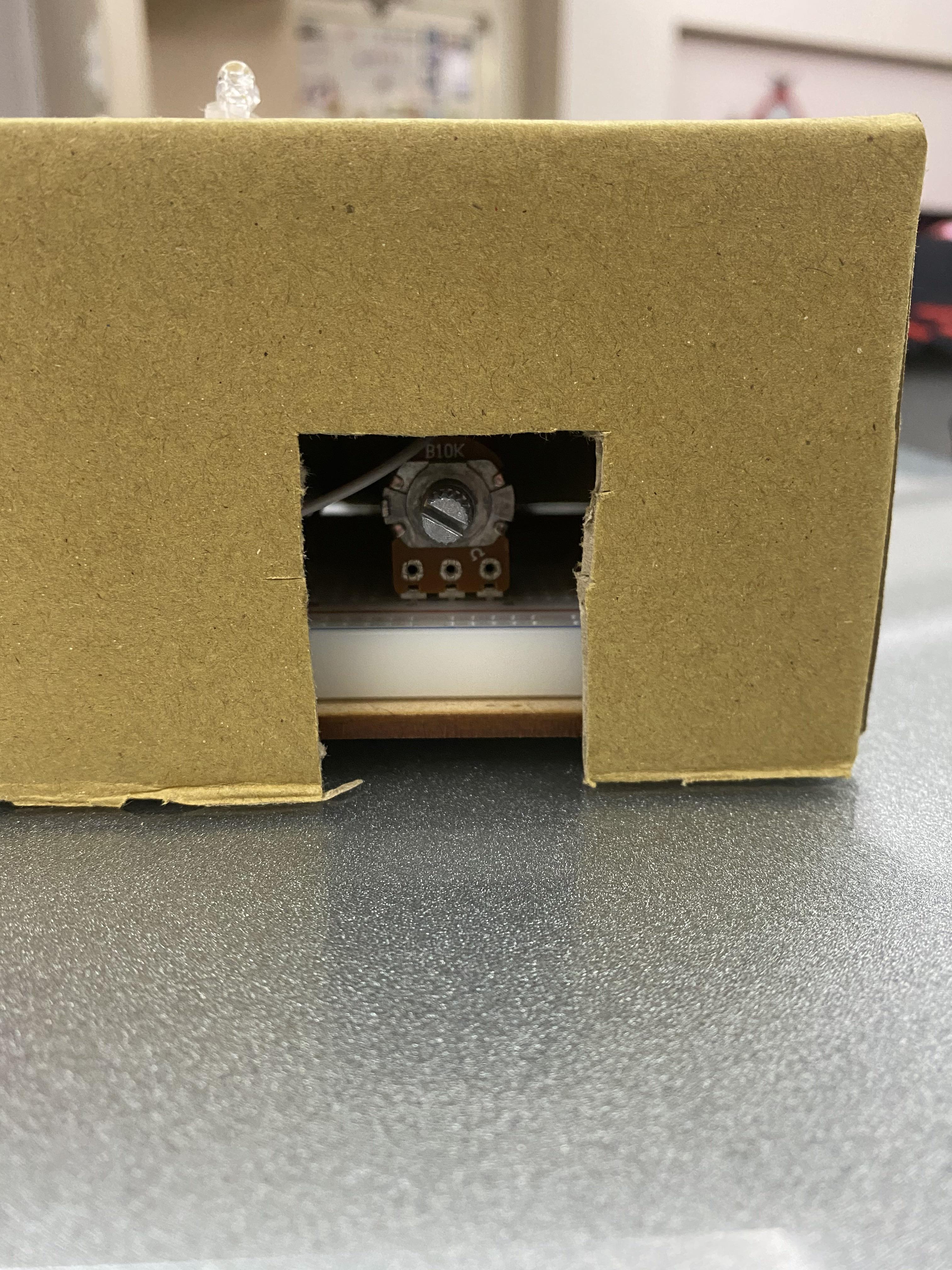
- Cut the hole for the potentiometer
- Cut the hole for USB power source output
- Use the tape to wrap around the connecting point of the LED and the wires to make sure it won't fall off.
- Place the LED inside the holes.
- Place the box onto the board, cover the wires, and align the potentiometer position with the hole.
- Connect Power and Shine!
Code
int potPin = 2;   //sets potentiometer pin at analog 2
int potVal = 0;   //holds the value read in from the potentiometer
int led1 = 11;    //pin number 11 has led1
int led2 = 10;    //pin number 10 has led2
int led3 = 9;     //pin number 9 has led3
int led4 = 6;     //pin number 6 has led4
int led5 = 5;     //pin number 5 has led5
byte full= 255;   //the highest brightness is 255
byte low = 50;   //the low brightness is 50
byte dim = 5;    //the dim is set to 5
byte off = LOW;   //and off has no voltage

void setup(){
  Serial.begin(9600);
  pinMode(potPin, INPUT); //potentiometer is an input
  pinMode(led1, OUTPUT);  //led1 is an output
  pinMode(led2, OUTPUT);  //led2 is an output
  pinMode(led3, OUTPUT);  //led3 is an output
  pinMode(led4, OUTPUT);  //led4 is an outut
  pinMode(led5, OUTPUT);  //led5 is an outut
}//end setup()

void loop(){
  //read in analog value from potentiometer and stores into potVal
  potVal = analogRead(potPin);
  //prints the value in the serial monitor
  Serial.print(potVal);
  //displays the brightness of each led based on the position of the potentiometer
  if(potVal>=0&&potVal<205)
  {
    digitalWrite(led1,full);
    digitalWrite(led2,low);
    digitalWrite(led3,dim);
    digitalWrite(led4,off);
    digitalWrite(led5,off);
  }
  if(potVal>=205&&potVal<410)
  {
    digitalWrite(led1,low);
    digitalWrite(led2,full);
    digitalWrite(led3,low);
    digitalWrite(led4,dim);
    digitalWrite(led5,off);
  }
  if(potVal>=410&&potVal<615)
  {
    digitalWrite(led1,dim);
    digitalWrite(led2,low);
    digitalWrite(led3,full);
    digitalWrite(led4,low);
    digitalWrite(led5,dim);
  }
  if(potVal>=615&&potVal<820)
  {
    digitalWrite(led1,off);
    digitalWrite(led2,dim);
    digitalWrite(led3,low);
    digitalWrite(led4,full);
    digitalWrite(led5,low);
  }
  if(potVal>=820&&potVal<1023)
  {
    digitalWrite(led1,off);
    digitalWrite(led2,off);
    digitalWrite(led3,dim);
    digitalWrite(led4,low);
    digitalWrite(led5,full);
  }
  //waits 100 ms
  delay(500);
}//end loop
Final Product Video

This is my final product.