Arduino LCD Tutorial
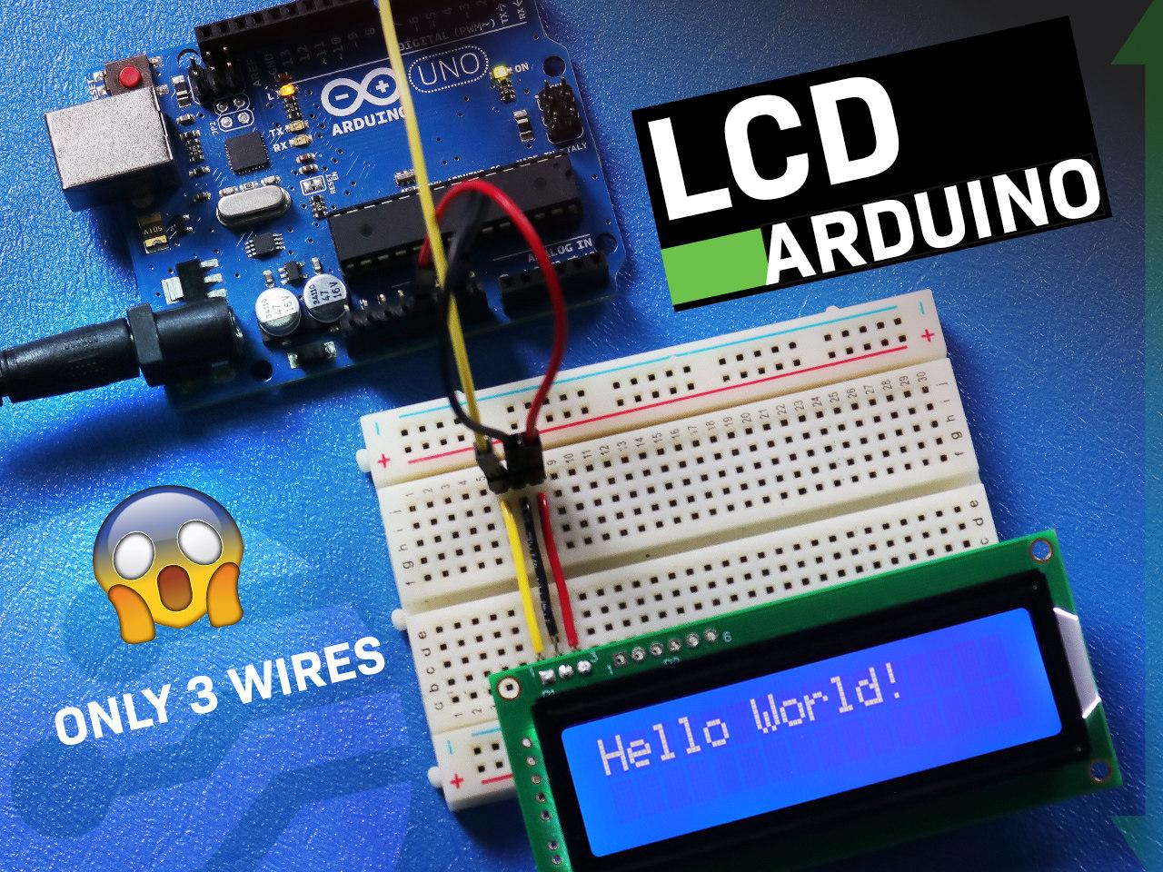
How to Connect LCD to Arduino Uno Using Serial Communication - 3 Wires Only
The LCD (Liquid Crystal Display) is a commonly used display for Arduino projects. It provides a simple way to output information to the user, such as text and basic characters. This tutorial will show you how to connect and interact between a 16x2 LCD Character Display and an Arduino UNO board using serial RS232 TTL communication.
The principles in this tutorial can be applied to other LCD displays and other development boards as well.
Supplies
Things needed to complete this tutorial
- LCD 16x2
- Single row pin header connector
- Arduino UNO
- breadboard
- Jumper wires
- Solder and soldering iron
- USB A male to B Male Cable (printer cable)
- Arduino IDE
- 0 ohm resistor (optional - for SPI communication only)
LCD & Arduino Pins
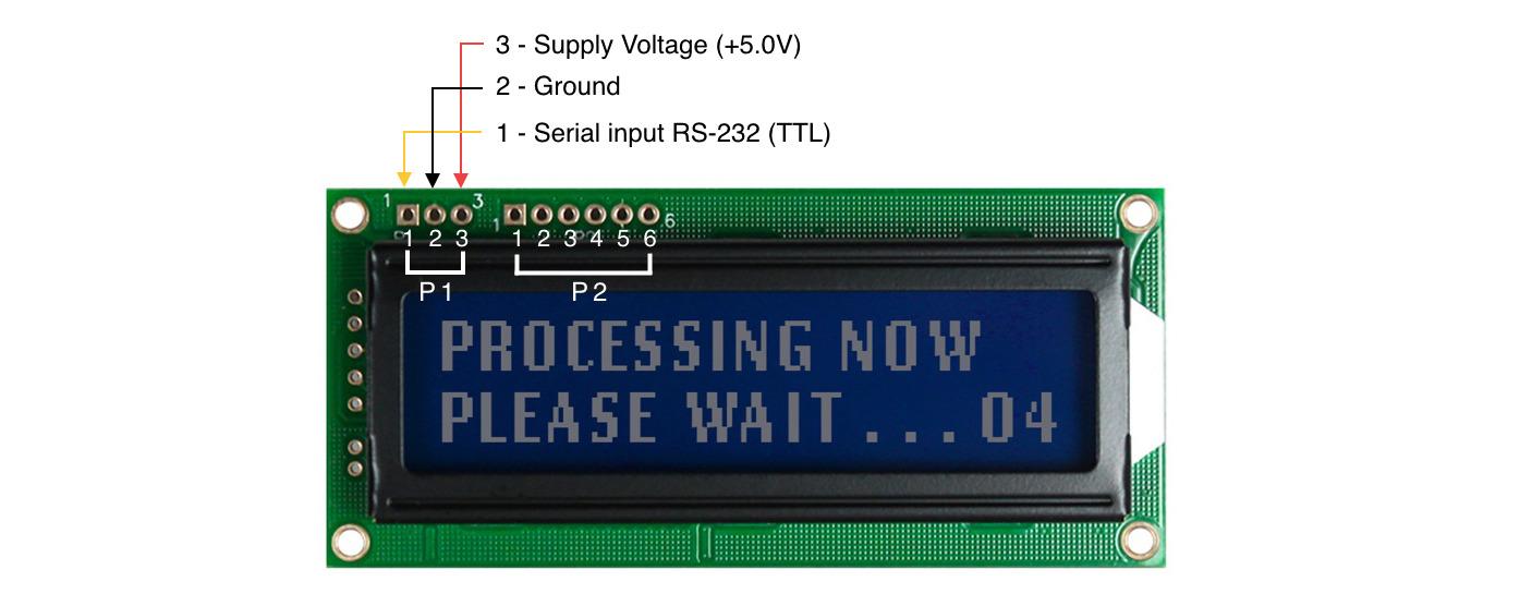
LCD Pinout
You can interface an LCD with Arduino via Serial and parallel communication. In this tutorial, we will use the 16x2 Newhaven Character Display, which is compatible with SPI, I2C, and RS232 TTL serial communication. The P1 port is specifically designed for RS232 TTL serial communication, while the P2 port is for serial I2C and SPI communication.
Communication with the display requires only 3 wires. The display attributes, such as contrast, backlight brightness, and other parameters, can be adjusted using specific command sequences that can be found in the LCD datasheet.
P1 Port Pin Description - RS232 TTL Serial Communication
- Pin 1 - RS-232 (TTL) Serial input
- Pin 2 - Ground
- Pin3 - Supply Voltage (+5.0V)
Arduino Pinout
The Arduino Uno has 14 digital pins, 6 analog pins, and a variety of other pins for power and communication. The digital pins can be used for both input and output, the analog pins can be used to read analog signals from sensors, and the power pins provide power to the Arduino Uno.
We will use the power and one digital pin to send data to the display:
- 5V pin
- Ground pin
- Pin 7 - Serial data output
Wiring Diagram & Circuit
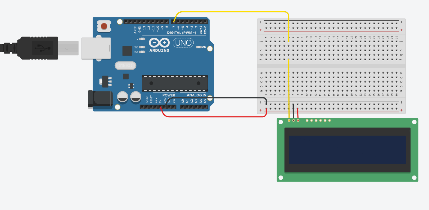
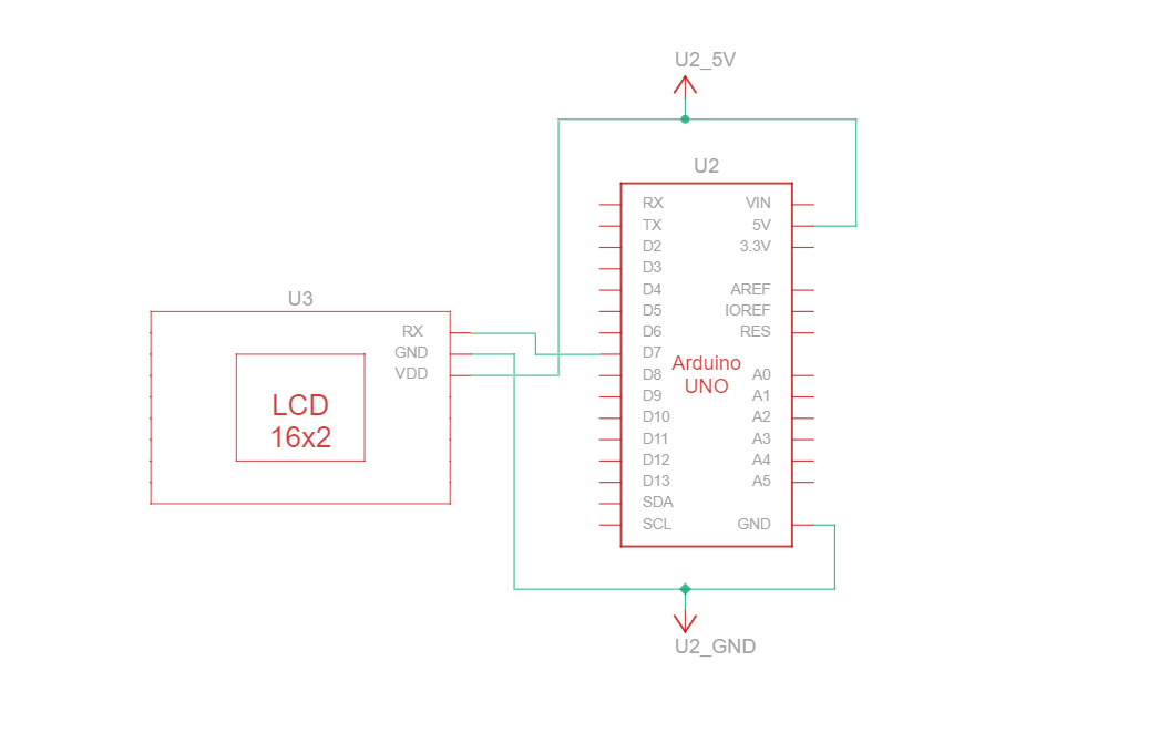
The circuit connecting the Arduino to the 16-character LCD via RS232 TTL serial communication requires just three cables - voltage, ground, and data.
Connect the Arduino's 5V pin to the LCD's VCC pin (pin 3), ground pin to the LCD's GND pin (pin 2), and digital pin 7 to the LCD's Rx pin (pin 1).
The Code
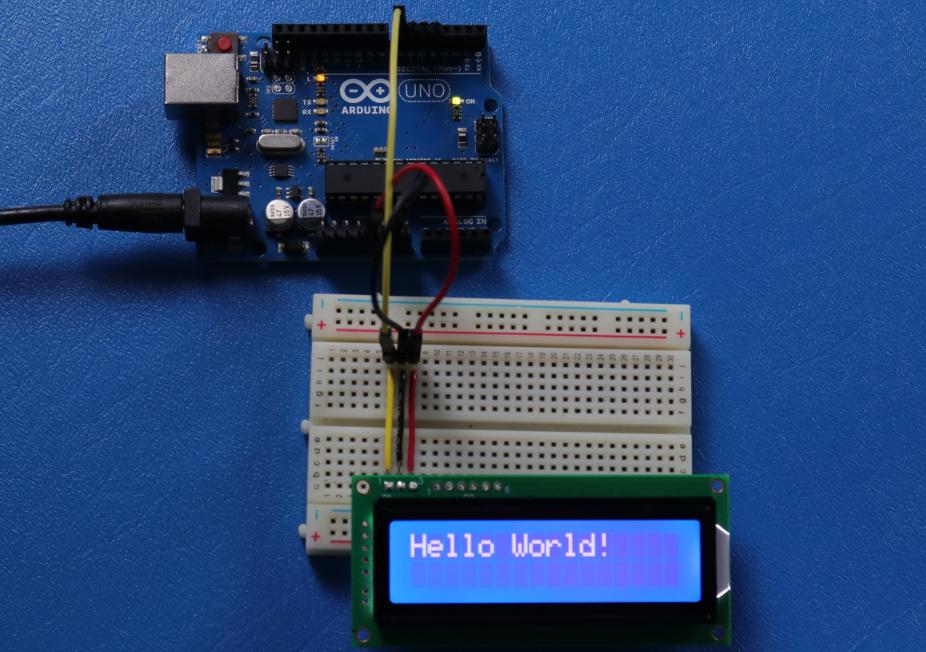
The code example below shows "Hello World!" on the LCD using serial RS232 TTL communication.
    /*****************************************************
  This code was written for the Arduino UNO using RS-232 Interface.
  /*  RS-232 Wiring Reference for: NHD-0216K3Z-NSW-BBW-V3
  ---------------------------
  LCD         |   Arduino
  ---------------------------
  1(RX)     --> 7
  2(VSS)    --> Ground
  3(VDD)    --> 5V
*/
#define P1 7  //RX the pin on which to receive serial data.
/*****************************************************
   RS-232 setup for command and data.
   For more information on RS-232 please visit our Support Center
  /*****************************************************/
#include <SoftwareSerial.h>
#define RxPin P1
SoftwareSerial NHD_LCD = SoftwareSerial(P1, RxPin);
/*****************************************************
   Set LCD Contrast
  /*****************************************************/
void Set_Contrast() {
  NHD_LCD.write(0xFE);  //Prefix command
  NHD_LCD.write(0x52);  //Contrast command
  NHD_LCD.write(0x28);  //Set contrast value
  delayMicroseconds(500);
}
/*****************************************************
   Clear LCD
  /*****************************************************/
void Clear_display() {
  NHD_LCD.write(0xFE);  //Prefix command
  NHD_LCD.write(0x51);  //Clear Display
  delayMicroseconds(1500);
}
/*****************************************************
   Set Arduino UNO IO ports as Output mode
  /*****************************************************/
void Set_Pins() {
  pinMode(RxPin, OUTPUT);
}
/*****************************************************
   Set LCD Backlight
  /*****************************************************/
void Set_Backlight() {
  NHD_LCD.write(0xFE);  //prefix command
  NHD_LCD.write(0x53);  //Backlight command
  NHD_LCD.write(0x08);  //Set backlight value
  delayMicroseconds(100);
}
/*****************************************************
   Set cursor
   Mode = 0 sets Blinking cursor off
   Mode = 1 sets Blinking cursor on
  /*****************************************************/
void Set_Cursor(int mode) {
  NHD_LCD.write(0xFE);  //Prefix command
  if (mode == 0) {
    NHD_LCD.write(0x4c);  //Turn blinking cursor off
  } else if (mode == 1) {
    NHD_LCD.write(0x4b);  //Turn blinking cursor on
  }
  delayMicroseconds(100);
}
/*****************************************************
   Write "Hello World!" to LCD
  /*****************************************************/
void Hello_World() {
  NHD_LCD.write(0x48);  // H
  NHD_LCD.write(0x65);  // e
  NHD_LCD.write(0x6C);  // l
  NHD_LCD.write(0x6C);  // l
  NHD_LCD.write(0x6F);  // o
  NHD_LCD.write(0x11);  // Blank
  NHD_LCD.write(0x57);  // W
  NHD_LCD.write(0x6f);  // o
  NHD_LCD.write(0x72);  // r
  NHD_LCD.write(0x6c);  // l
  NHD_LCD.write(0x64);  // d
  NHD_LCD.write(0x21);  // !
}
/*****************************************************
  Main function
/*****************************************************/
void setup() {
  NHD_LCD.begin(9600);  //Sets 9600 Baud Rate the display can receive and transmit data at a rate of 9600 bits per second by default.
  delay(15);
  Set_Pins();       //Set IO ports
  Set_Cursor(0);    //Turns off blinking cursor
  Set_Contrast();   //Set display Contrast
  Set_Backlight();  //Set display Backlight
  Clear_display();  //Clear display
  Hello_World();    //Display "Hello Wolrd!"
}
void loop() {
}
Code Breakdown:
Initialization:
The P1 7 constant is defined, which is used for receiving serial data (RX). The SoftwareSerial library is included, and a new object named NHD_LCD is created, specifying the RX pin.
Set LCD Contrast:
The Set_Contrast() function adjusts the contrast of the LCD. It sends a series of commands to the LCD to set a specific contrast value.
Clear LCD Display:
The Clear_display() function sends commands to the LCD to clear the display.
Set Arduino UNO IO Ports:
The Set_Pins() function sets the RX pin as an output.
Set LCD Backlight:
The Set_Backlight() function adjusts the backlight of the LCD.
Set Cursor Mode:
The Set_Cursor() function sets the blinking cursor mode on/off.
Display "Hello World!":
The Hello_World() function sends individual characters to the LCD to display the message "Hello World!".
Main Functions:
setup(): This function is executed once when the Arduino starts. It initializes the LCD with a baud rate of 9600, sets the IO ports, adjusts the cursor, contrast, and backlight, clears the display, and finally displays "Hello World!" on the LCD.
loop(): This function is empty and runs continuously after the setup() function. In this code, no operations are performed in the loop.
Load Code to the Arduino Board
- Install the Arduino IDE: Download and install the Arduino IDE (Integrated Development Environment) from the official Arduino website.
- Connect your Arduino: Using the USB cable, connect your Arduino board to your computer.
- Open the Arduino IDE: Launch the Arduino IDE on your computer.
- Select your board: Go to Tools > Board and select the Arduino Uno board, or simply select it from Select Board field navigation menu.
- Load your code: Go to File > New Sketch and remove all code loaded by default. Copy the code above and paste it into the code editor.
- Verify the code: Click on the ✓ (checkmark) button located at the top left corner of the IDE. This will compile and check your code for errors.
- Upload the code: Once the code is verified without errors, click on the → (right arrow) button located next to the checkmark. This will upload your code to the Arduino board. After uploading, your Arduino should start running the uploaded code immediately.
And that's it! Your Arduino should now be displaying Hello World!
LCD - Arduino Connection Using SPI Communication
If you are interested in following the SPI communication tutorial, you can find resources below that will help you do so using the same display with just a few modifications to the circuit.
- Circuit connection for SPI communication between a 16x2 LCD and Arduino
- Display text on the first and second row code example
- Display long text code example
- Blink - Display text with a blinking cursor code example
- Cursor + autoscroll text code example
- Auto scroll text code example
- Adjusting the LCD contrast with code
- How to use the LCD backlight code example
- Characters/font tables code example