Arduino Intruder Alarm
.png)
Whether it's guarding your room, or protecting your house from intruders, there are several uses for a motion-activated alarm. This project will teach you about Arduino, as well as giving you several other useful skills in the world of engineering.
Supplies
Connecting the Buzzer to the Arduino
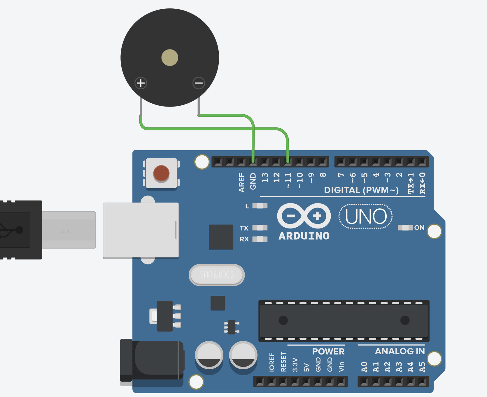
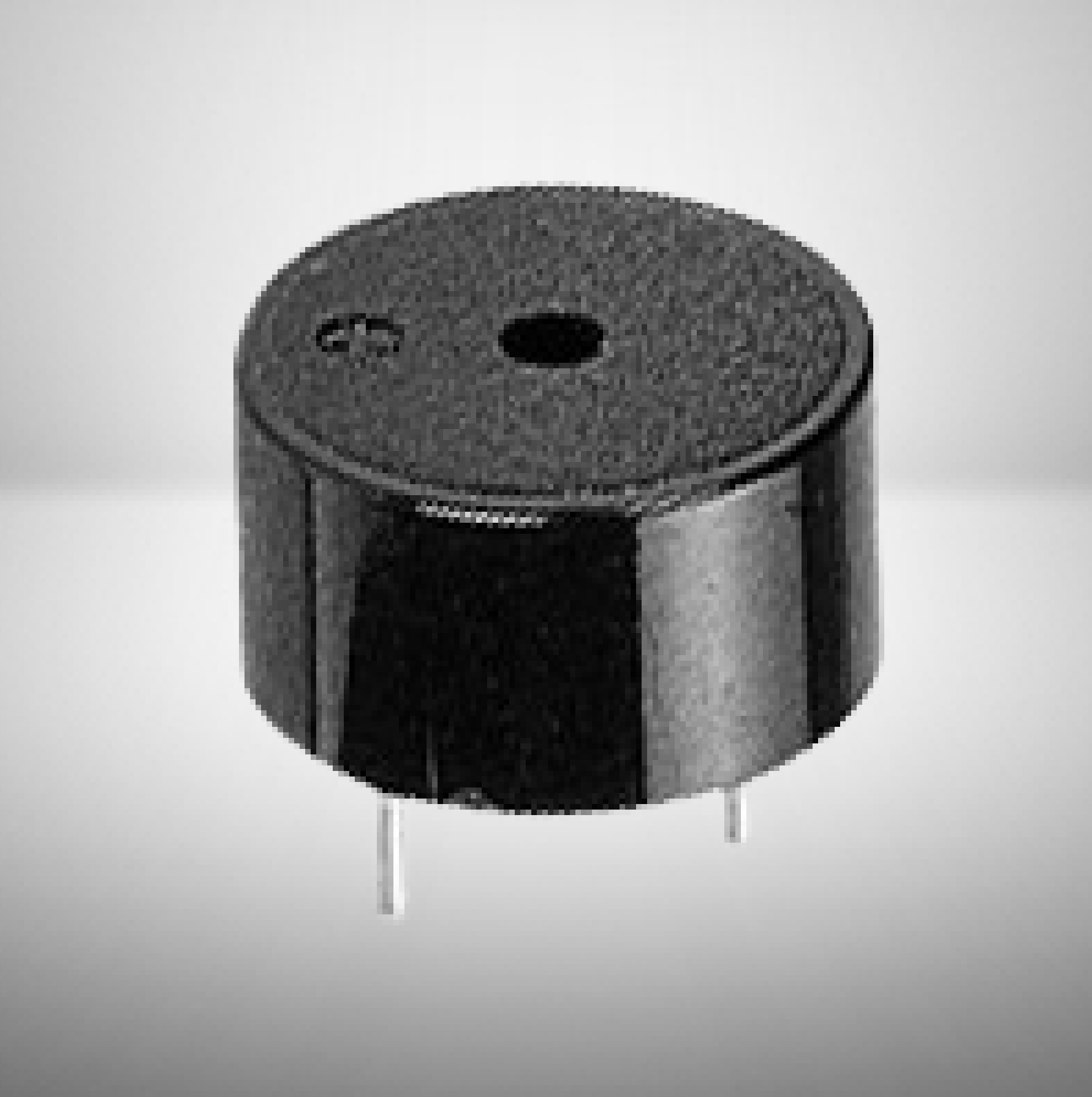
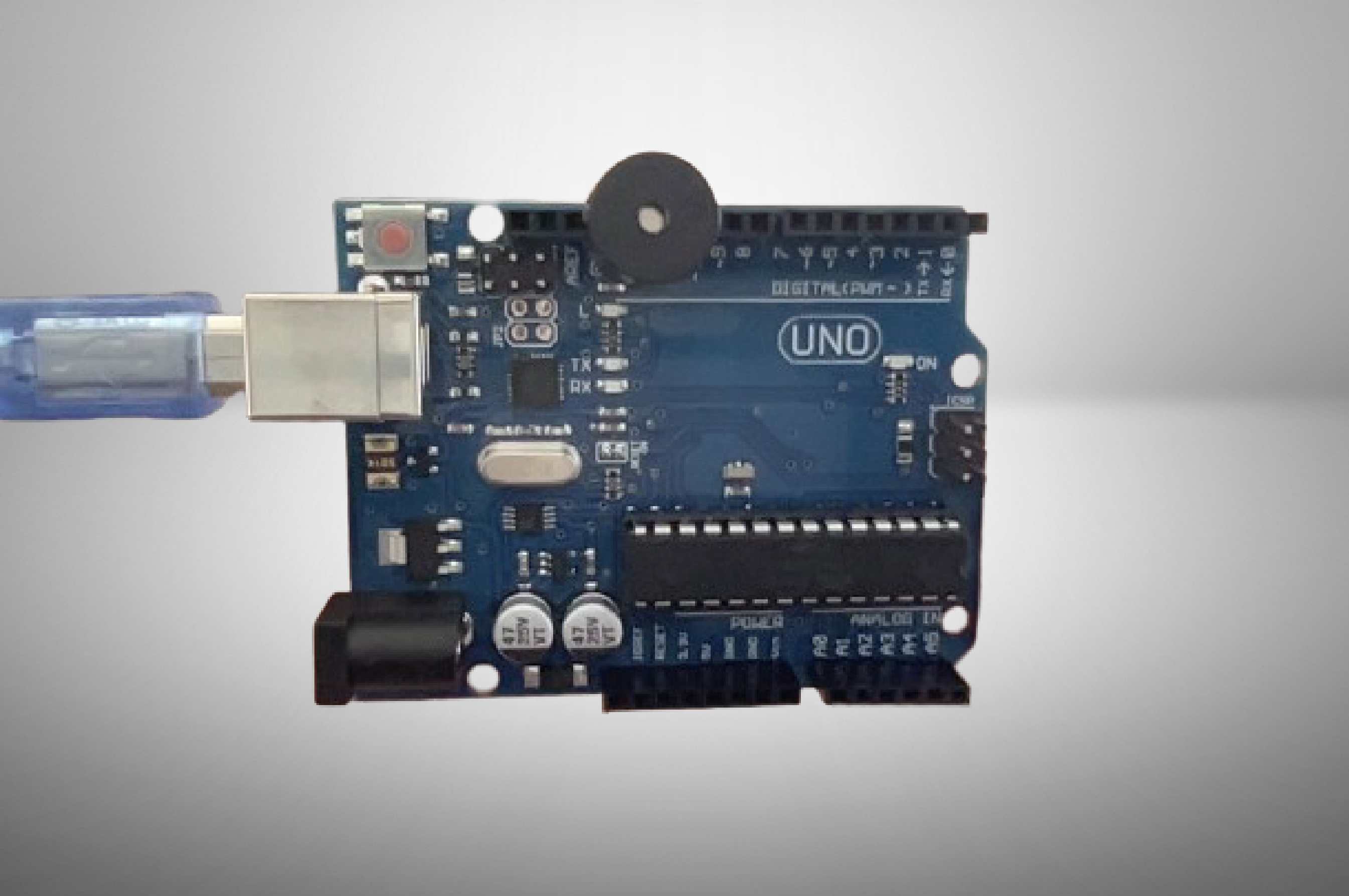
Connect the longer leg of the piezo sounder to pin 11, while the shorter leg goes into GND of the Arduino UNO as shown in the three images above. No wired are needed for this step, as you can just insert each prong into the Arduino UNO directly.
Preparing the PIR (passive Infrared) Sensor
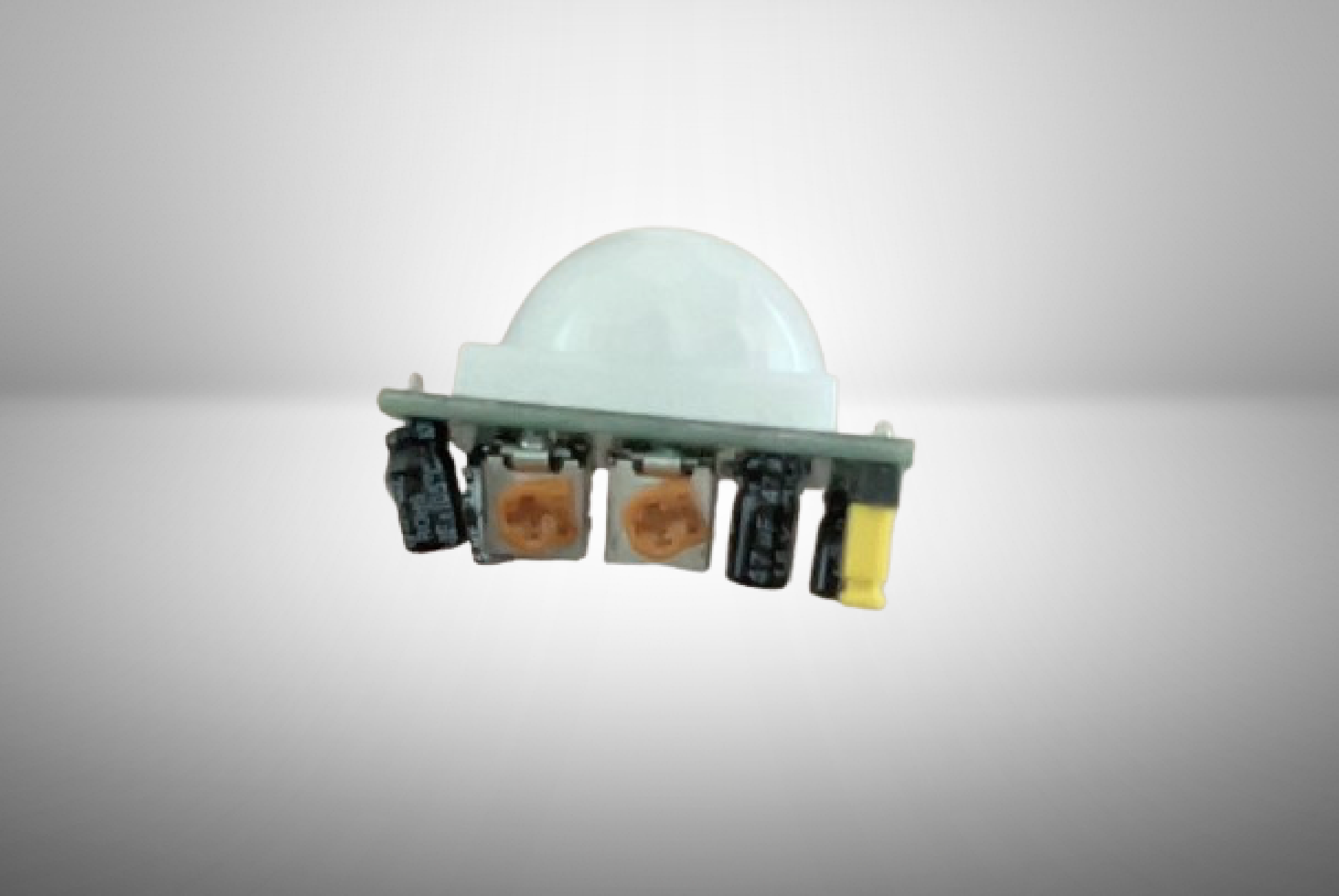
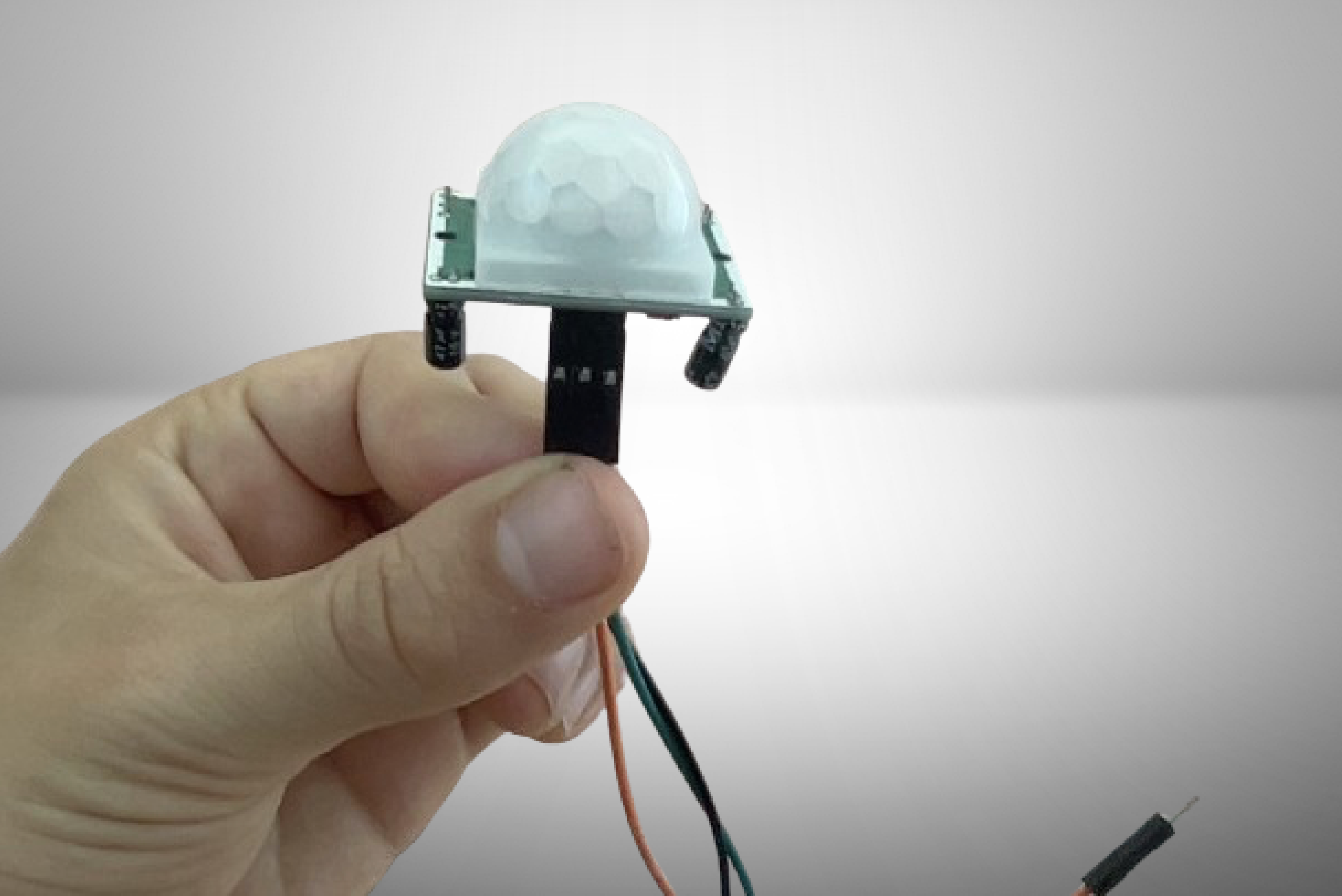
Rotate the two orange potentiometers on the PIR sensor to the positions as shown in the first image. Next, attach jumper wires to each of the pins of the PIR sensor as shown in image two. The color of the jumper wires do not matter.
Wiring the PIR (Passive Infrared) Sensor
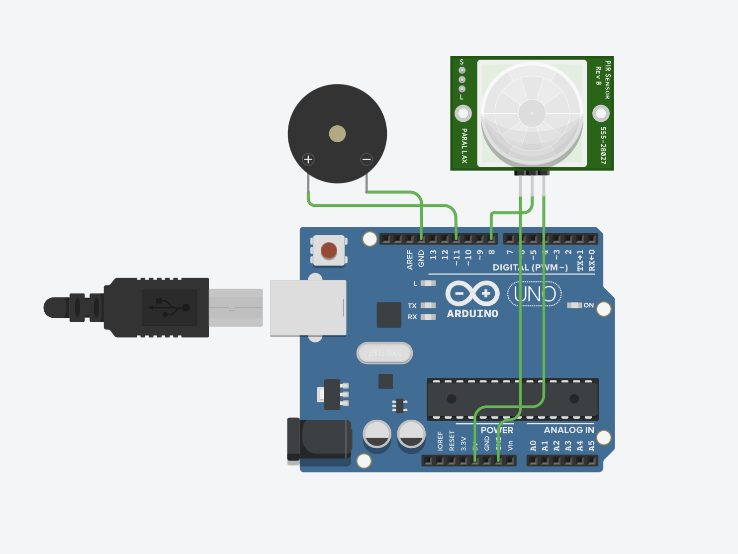
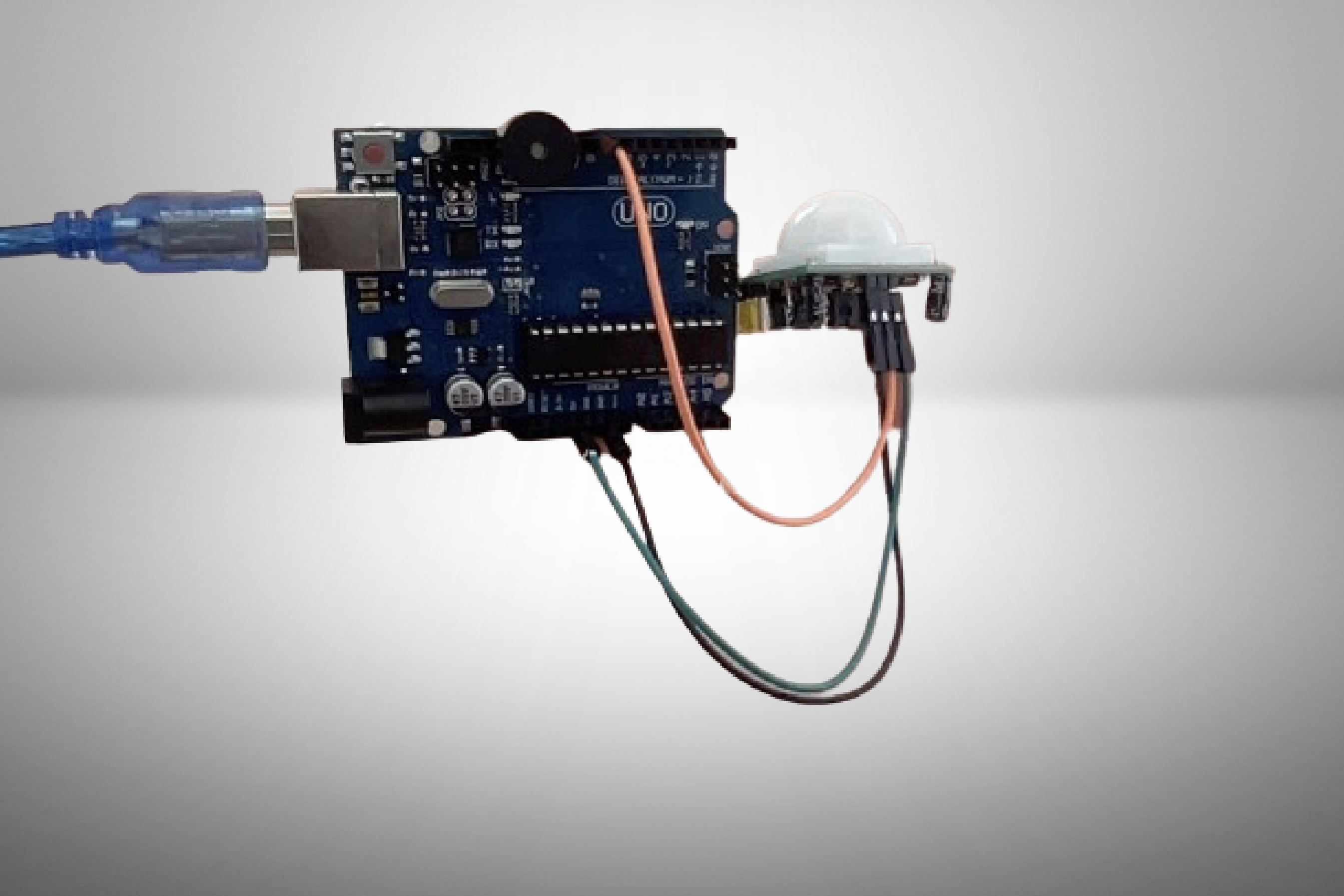
Insert the jumper wire plugged into the far left pin of the PIR sensor into the GND pin of the Arduino as shown in the wiring diagram above. Insert the wire plugged into the middle pin of the PIR sensor into digital pin 8. Insert the wire plugged into the rightmost pin of the PIR sensor into the 5v pin of the Arduino UNO as shown also by the wiring diagram. Your build should now look like image 2.
The Code
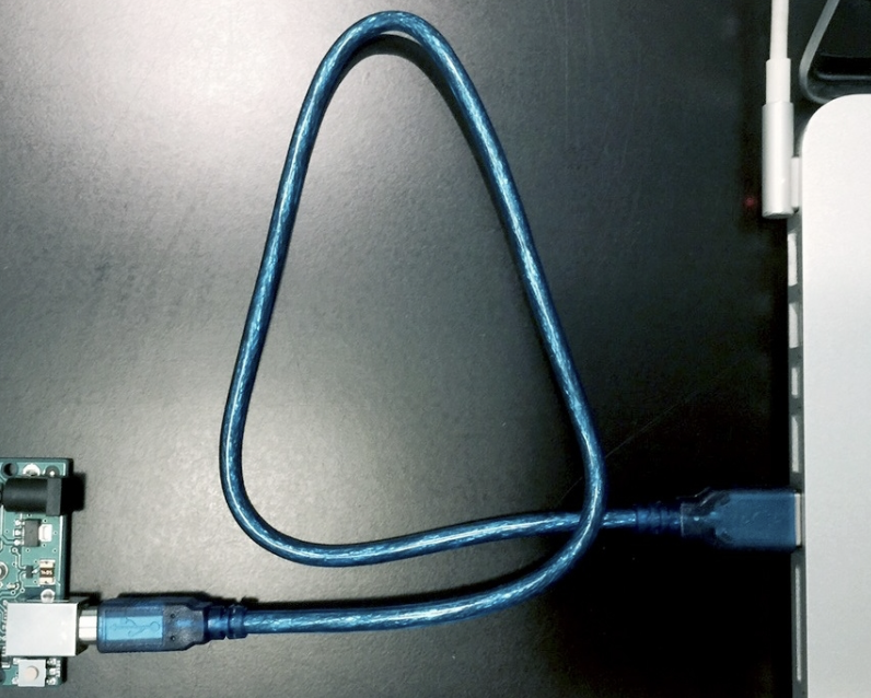
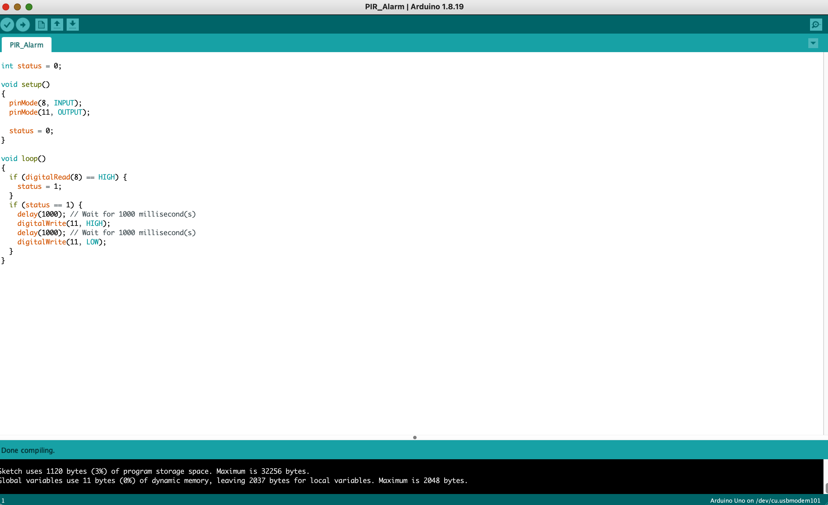
If you have not already done so, Connect a USB 2.0 type A/B cable into the Arduino. Next, connect the cable from your Arduino UNO into the USB port of your computer. If your computer only has USB-C, then use an adapter to convert USB to USB-C. After that, copy and paste the code below into the Arduino IDE. Next, click the arrow button in the Arduino IDE just to the right of the checkmark in the top left corner to upload the code.
int status = 0;

void setup()
{
  pinMode(8, INPUT);
  pinMode(11, OUTPUT);

  status = 0;
}

void loop()
{
  if (digitalRead(8) == HIGH) {
    status = 1;
  }
  if (status == 1) {
    delay(1000); // Wait for 1000 millisecond(s)
    digitalWrite(11, HIGH);
    delay(1000); // Wait for 1000 millisecond(s)
    digitalWrite(11, LOW);
  }
}
Test
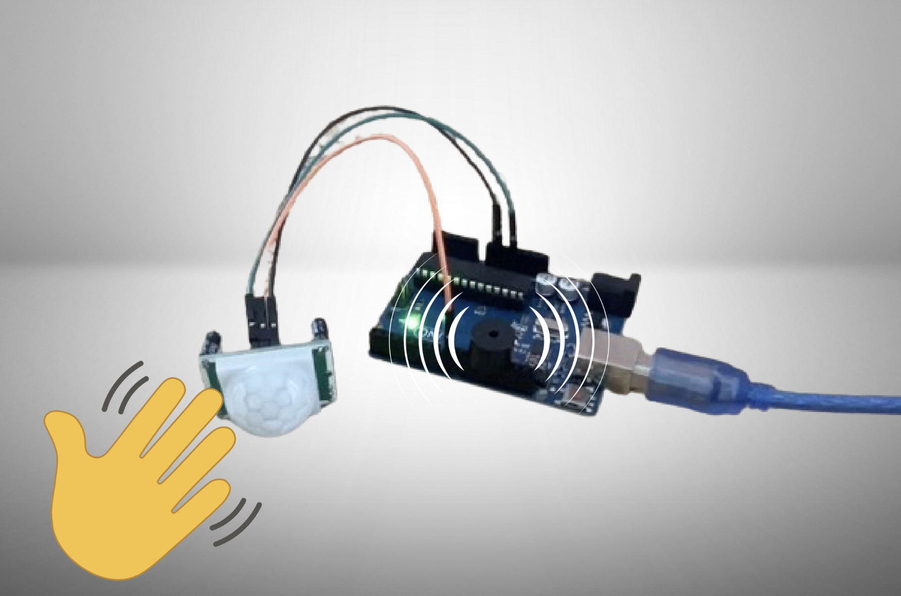
Next, plug in the Arduino Uno and wave your hand in front of the PIR sensor. This should triggering the alarm to sound. If this does not happen, consult the troubleshooting guide at the end of this Instructables.
Switching the Type of Cable
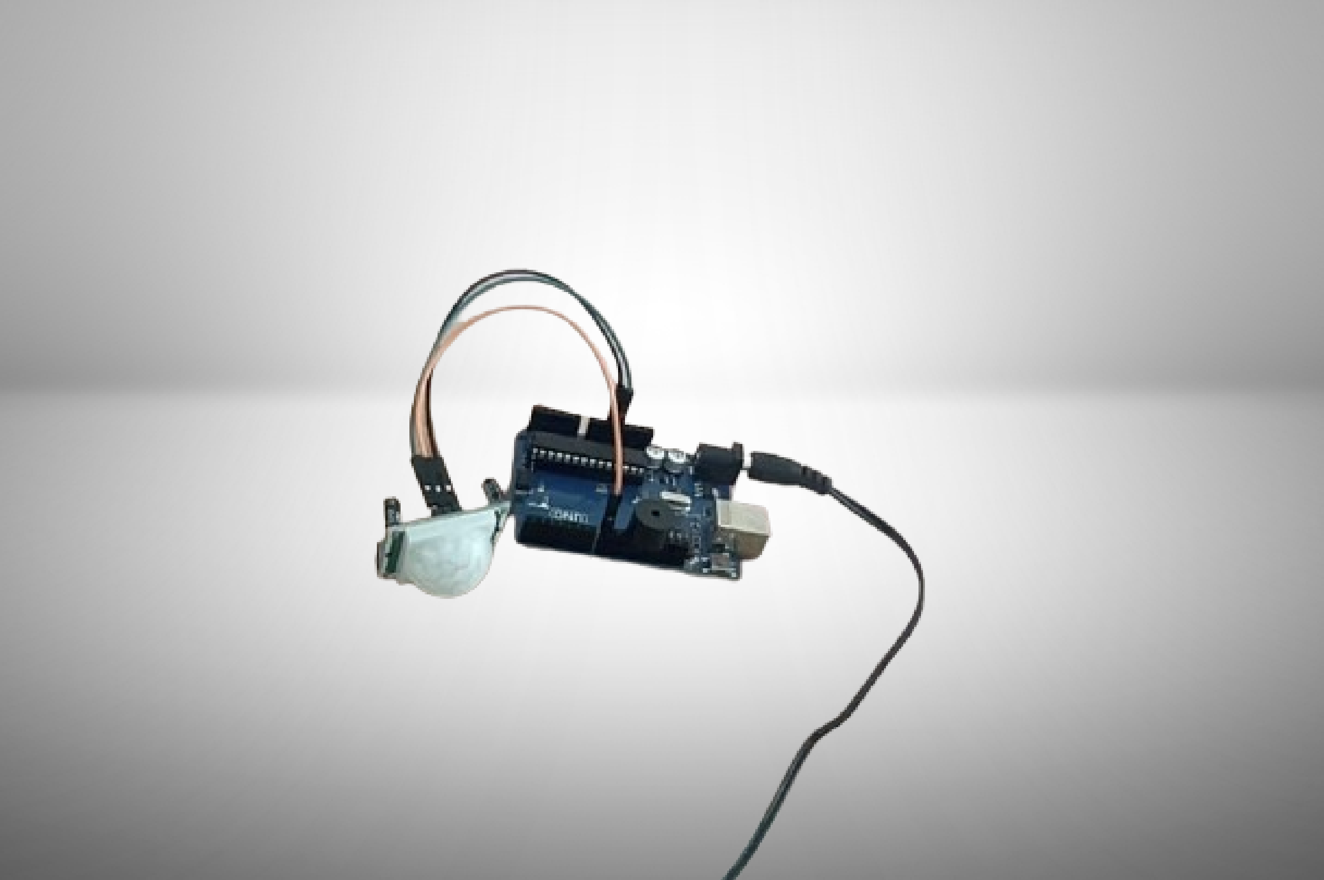
Unplug your USB 2.0 type A/B cord from your Arduino and your computer, and replace it with a barrel jack cable inserted into the little black part just to the right of where the prior cable was plugged in as shown in the image for this step.
Laser Cutting

After that, download and laser cut the file below. I formatted it for a Universal Laser Systems laser cutter, though it should be relatively easy to format it so that your laser cutter can cut it.
Downloads
Assembling Some of the Laser Cut Pieces
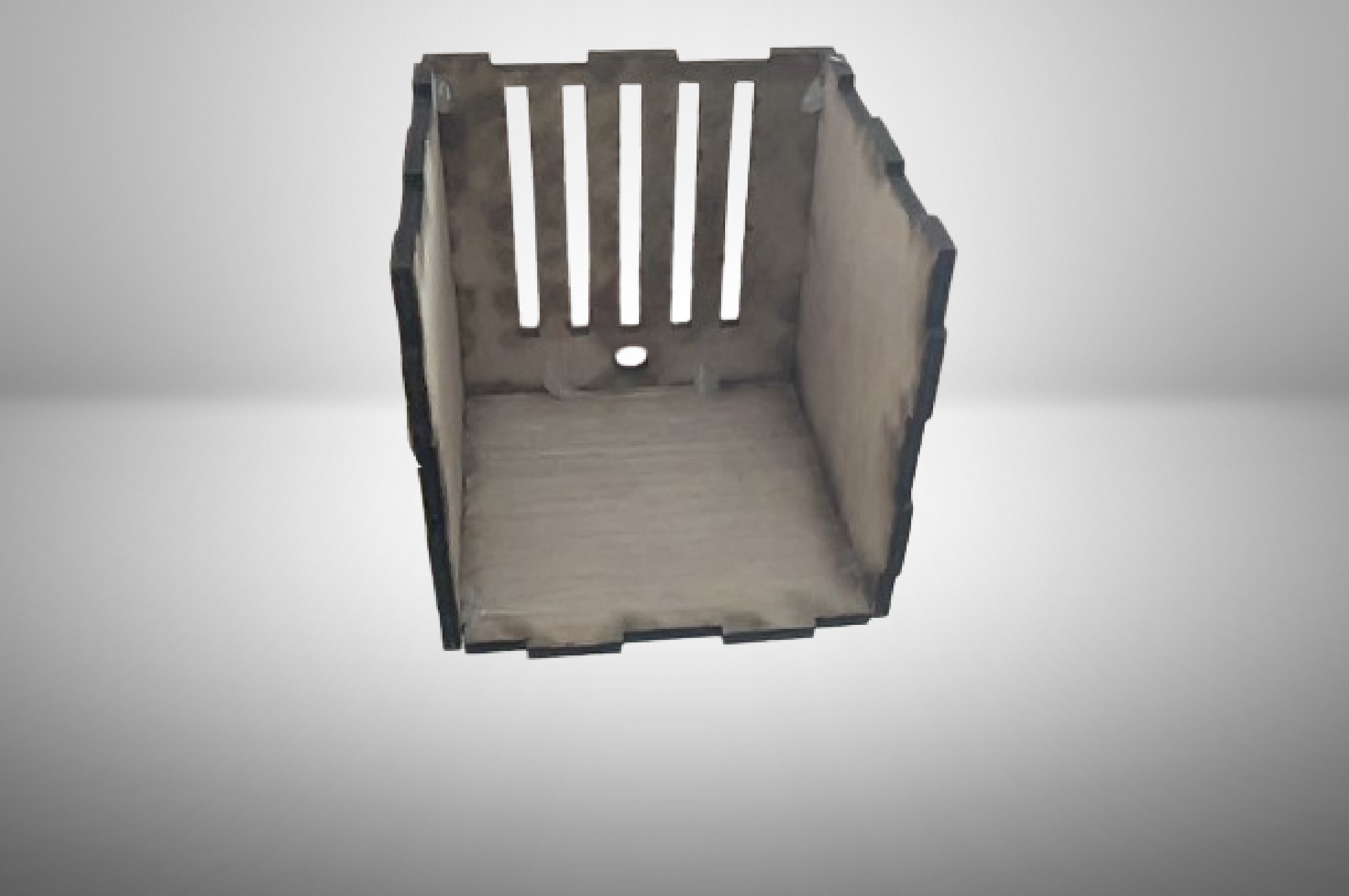
Using a hot glue gun, assemble the four sides that are shown in the image for this step.
Inserting the Circuit Into the Laser Cut Casing
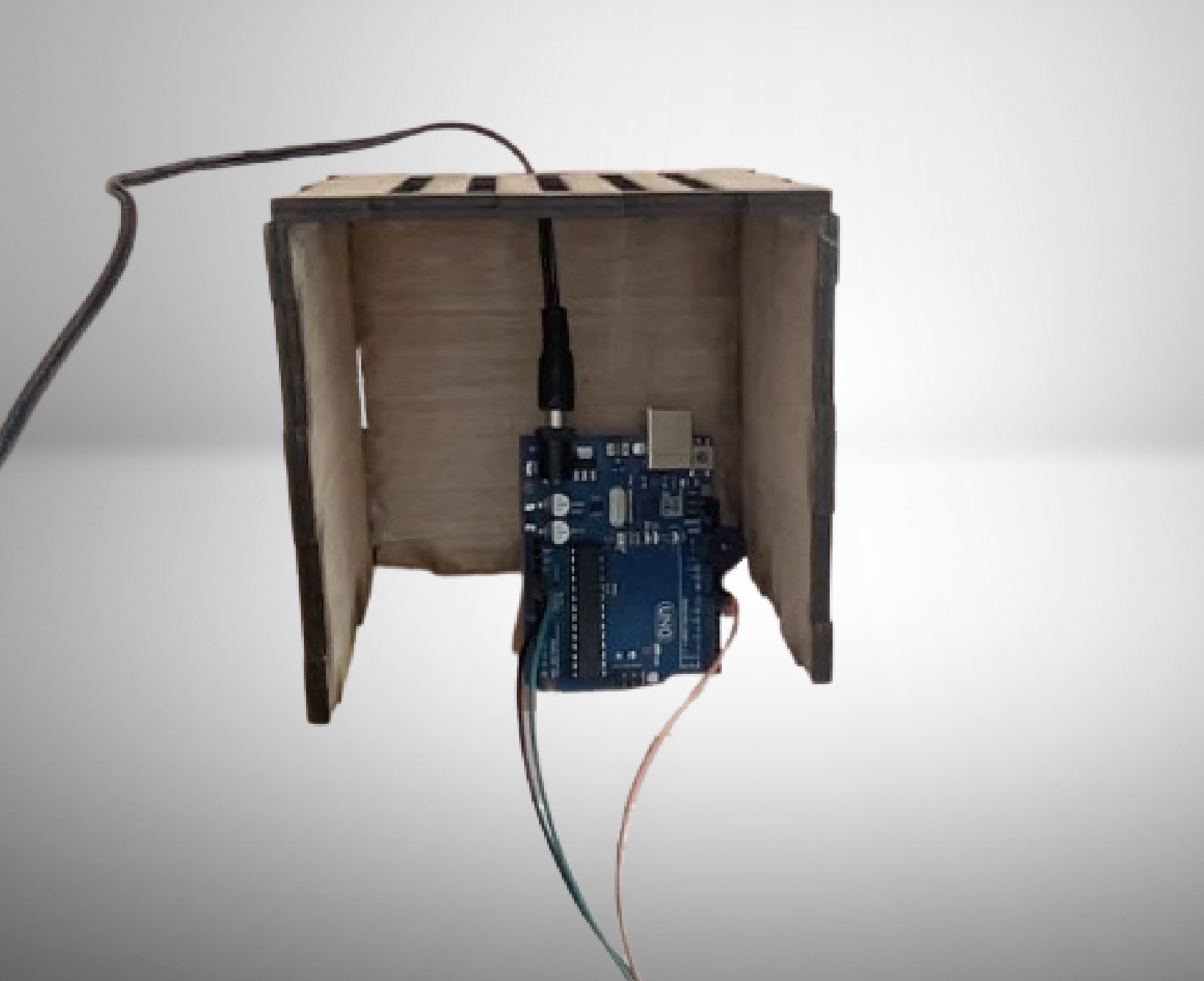
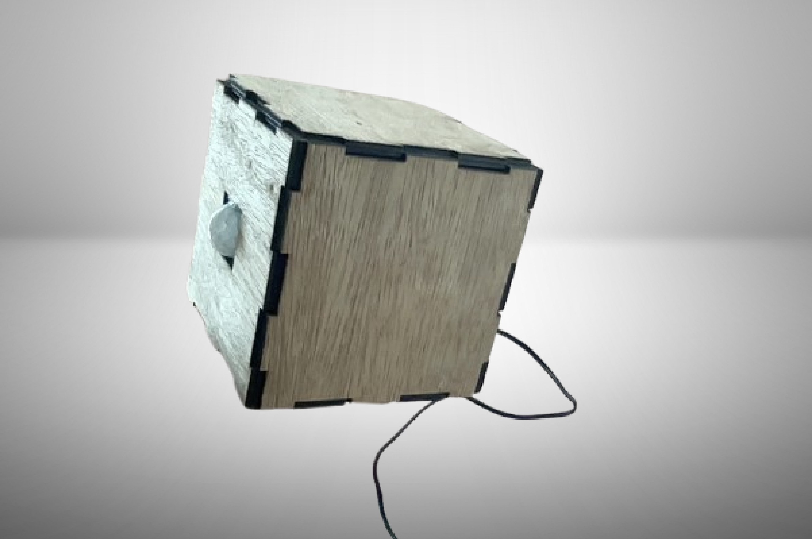
Unplug the cable connected to the Arduino UNO, and then thread it through the small hole on the side with the slit cutouts, and then proceed to plug it back in, getting a result like the image above.
Inserting the PIR (passive Infrared) Sensor
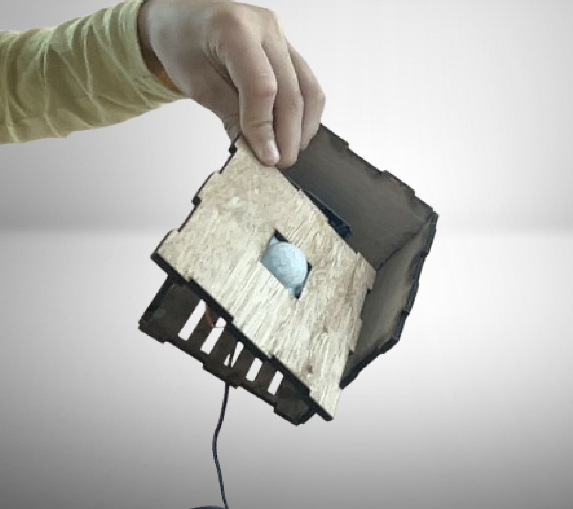
Using the hot glue, glue the PIR sensor into the wood panel with the 1 inch square cut out of it as shown by the image above.
Assembling the Last Two Panels
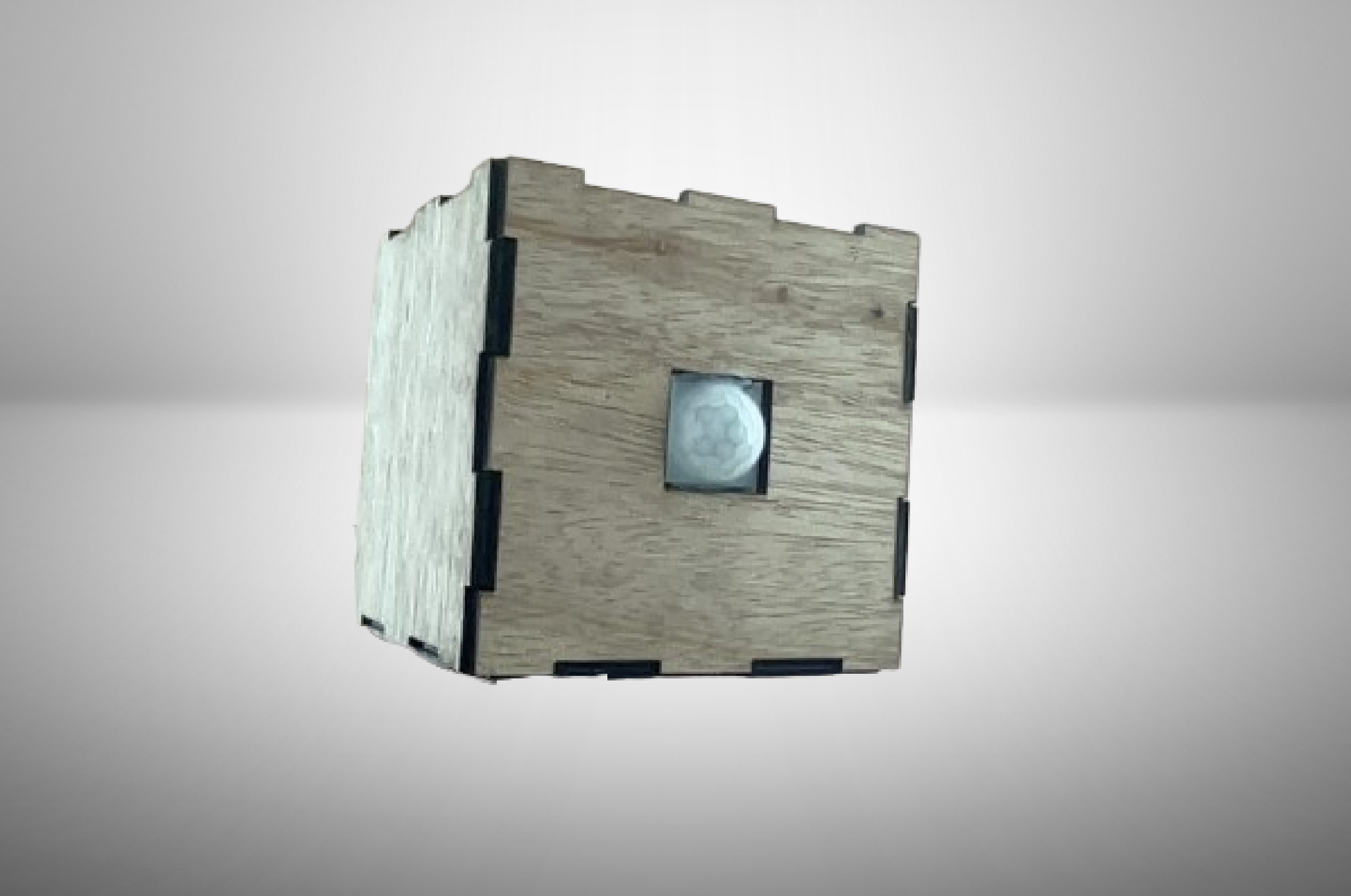
Then, glue the panel with the PIR sensor panel to the front of the box (The back of the box is the panel where the power cord comes out). After that, place the lid on top. Do not glue it on, as you may need to open up the box again incase something breaks internally.
Troubleshooting
Tip 1: Make sure all of your wires are connected to the correct pins.
Tip 2: Make sure you copy and pasted all of the code, and not just a small portion of it.
Tip 3: Make sure that none of your components are faulty.
Tip 4: If your buzzer is sounding immediately after you turn it on, click the reset button.