Arduino Home Alarm System

This is a great Arduino project that you can start with basic Arduino components. This project will act as an alarm system an alert an individual if someone has invaded a certain area of choice. It is great if you're planning to start a project that is not too easy nor it is too hard! You can definitely create this project through TinkerCad or with physical Arduino components.
Step 1: Gather All Materials


_f6ucGPuaDx.jpg)
For this Arduino Project, you will need...
- Arduino Uno Board
- Bread board
- Jumper wires
- Buzzer
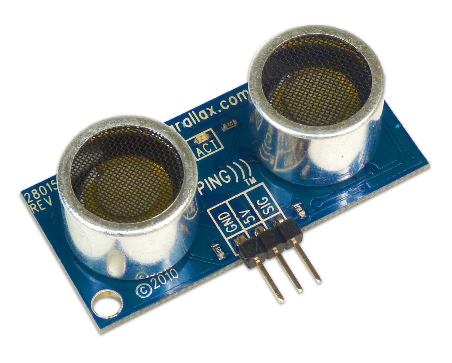
- Distance Sensor
- Motion Sensor
- LCD Display 16*2
- Potentiometer
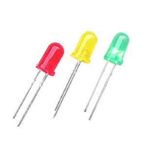
- 2 LEDs (red and another colour of choice)
- 220 Ohm Resistor
Step 2: Assemble Simple Components

Before starting, power the breadboard with 5V using jumper wires, and connect the GND pin to ground on the breadboard. Make sure that each both sides of the breadboard receive power and ground. To begin with, assemble the simple components of the Alarm System.
Ultrasonic Distance Sensor
- Connect the Ground Pin to Ground
- Connect the Power Pin to Power
- Connect Trigger Pin to Pin 12 on the Arduino
- Connect Echo Pin to Pin 13 on the Arduino
Buzzer
- Connect the negative leg of the Buzzer to Ground
- Connect the positive leg of the Buzzer to Power
LEDs
- Connect the Red LED to pin 6 on the Arduino and the Cathode to ground
- Connect the Yellow LED to pin 2 on the Arduino and the Cathode to ground
Motion Sensor
- Connect Power pin to power
- Connect Ground pin to ground
- Connect Signal pin to pin 3 on the Arduino
Step 3: Assembling LCD and Potentiometer
Potentiometer
- Connect Terminal 1 to GND
- Connect Terminal 2 to Power
- Connect Wiper to V0 on the LCD display
LCD Display
- Connect GND Pin to Ground on the breadboard
- Connect VCC to power on the breadboard
- Connect VO to the wiper pin on the LCD display
- Connect RW to GND
- Connect 'E' (enable) to Pin 4 on the Arduino
- Connect DB4 to 8 on the Arduino
- Connect DB5 to 9 on the Arduino
- Connect DB6 to 10 on the Arduino
- Connect DB7 to 11 on the Arduino
- Connect LED pin to 220 Ohm resistor that connects to power
- Connect the LED pin (the first pin to the left) to GND
Step 4: the Code

Here is the Code: