Arduino HMI Using State Machines
by RobinH107 in Circuits > Arduino
3670 Views, 6 Favorites, 0 Comments
Arduino HMI Using State Machines

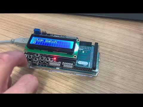
In this Instructable, I will show you how to use YAKINDU Statechart Tools to realize a simple and expandable HMI by using a 16x2 LCD Keypad Shield for Arduino.
Finite State Machines (FSM) are a powerful design pattern to develop complex Human Machine Interfaces (HMI). As the functionality of an HMI can increase, it is useful to use a design pattern like state machines.
The complete example is embedded in YAKINDU Statechart Tools. Additionally, the Eclipse C++ IDE for Arduino Plugin has been used for compiling and flashing in the IDE.
A Brief Synopsis of YAKINDU Statechart Tools
With this tool, it is possible to create graphical state machines. It allows the user to generate C, C++ or Java code from the state machine. With this approach, the model can be changed or expanded and the user can simply re-generate the code and does not have to write plain source code.
Supplies
The Hardware

The LCD Keypad Shield can simply be plugged into the Arduino. It has a 16x2 LCD Display and additionally got six pushbuttons:
- Left
- Right
- Up
- Down
- Select
- (Reset)
Obviously, five of them can be used. The keys are wired to a voltage divider and are detected by using Pin A0 depending on the voltage. I've used software debouncing to detect them correctly.
Define How It Should Work

The application should be capable to do three things.
- Handle States
Here I want to use the buttons to navigate between five states: Top, Middle, Bottom, Left and Right - Stopwatch
A simple stopwatch, which can be started, stopped and reset. It should be incremented every 100 milliseconds - Counter
The third part contains a simple up/down counter. It should be able to count positive numbers and it should be resettable
The active menu (or the state) will be displayed on the 16x2 LCD on the top line. The application (State, Timer or Counter) will be displayed on the bottom line. For navigation, the left and right pushbutton should be used.
Interfacing the State Machine
The buttons will be debounced and wired to the state machine. They can be used as in events in the state machine. Additionally, operations are defined to display the current menu. And at least two variables, one for the timer and one for the counter, are defined.
interface:

// buttons as input events
in event right
in event left
in event up
in event down
in event select

// display HMI specific values
operation displayLCDString(value:string, length:integer, position:integer)
operation displayLCDInteger(value:integer, position:integer)
operation clearLCDRow(position:integer)

internal:

//variables for storage
var cnt : integer
var timeCnt : integer = 0
After generating the C++ code, the in events must be debounced and wired to the interface. This code snippet shows how to do this.
At first, the buttons will be defined:
#define NONE 0<br>#define SELECT 1
#define LEFT 2
#define DOWN 3
#define UP 4
#define RIGHT 5
Then there is a function defined to read the button. The values may vary, depending on the LCD Shield manufacturer.
static int readButton() {<br>    int result = 0;
    result = analogRead(0);
    if (result < 50) {
        return RIGHT;
    }
    if (result < 150) {
        return UP;
    }
    if (result < 300) {
        return DOWN;
    }
    if (result < 550) {
        return LEFT;
    }
    if (result < 850) {
        return SELECT;
    }
    return NONE;
}
At the end, the buttons will be debounced. I did good results with 80 ms. Once a button will be released, it will raise the according in event.
int oldState = NONE;<br>static void raiseEvents() {
    int buttonPressed = readButton();
    delay(80);
    oldState = buttonPressed;
    if (oldState != NONE && readButton() == NONE) {
        switch (oldState) {
        case SELECT: {
            stateMachine->raise_select();
            break;
        }
        case LEFT: {
            stateMachine->raise_left();
            break;
        }
        case DOWN: {
            stateMachine->raise_down();
            break;
        }
        case UP: {
            stateMachine->raise_up();
            break;
        }
        case RIGHT: {
            stateMachine->raise_right();
            break;
        }
        default: {
            break;
        }
        }
    }
}
HMI Control

Each state is used for one part of the menu. There are sub-states, where the application - for example the stopwatch - will be executed.
With this design, the interface can be easily expanded. Additional menus can be simply added by using the same design pattern. Reading a value of a sensor and display it in a fourth menu item is no big deal.
For now, only left and right is used as a the control. But up and down can also be used as a navigation extension in the main menu. Only the select button will be used to enter a specific menu item.
Handle States

The handle states menu is only used as a further example of navigation. Using up, down, right or left allows switching between the states. The current state will always be printed on the second line on the LCD Display.
Stopwatch

The stopwatch is quite simple. Initially, the timer value will be reset. The timer can be started by using the left button and toggled by using left and right. Using up or down resets the timer. The timer can also be set back to zero by using the select button twice - leaving the menu and entering it once again, as the timer will be set to zero by initially entering the stopwatch.
Counter

At least, there is a counter implemented. Entering the counter state resets the counter. It can be started by using any pushbutton, except for the select button. It's implemented as a simple up/down counter, which value cannot be smaller than 0.
Simulation

Get the Example
You can download the IDE here: YAKINDU Statechart Tools
Once you have downloaded the IDE, you find the example via File -> New -> Example
It's free to use for hobbyists, but you also can use a 30 days trial.