Arduino GPS Clock With Local Time Using NEO-6M Module
by RonFrtek in Circuits > Arduino
5724 Views, 11 Favorites, 0 Comments
Arduino GPS Clock With Local Time Using NEO-6M Module
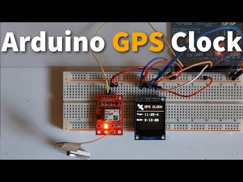
In this tutorial we will learn how to get a current time from the satellites using arduino.
Watch the video!
What You Will Need
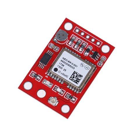
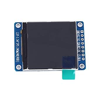
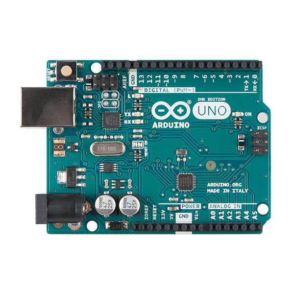
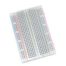
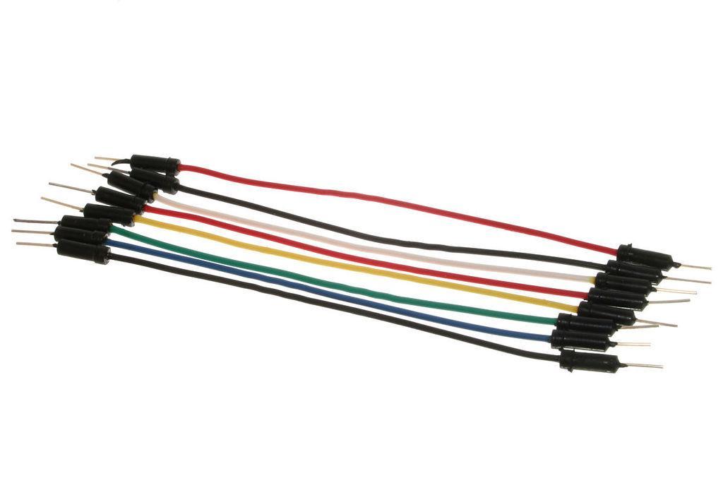
- NEO-6M GPS Module
- ST7789 TFT Display
- Arduino Uno or any other Arduino board
- Breadboard
- Jumper wires
- Visuino software: Download here
The Circuit
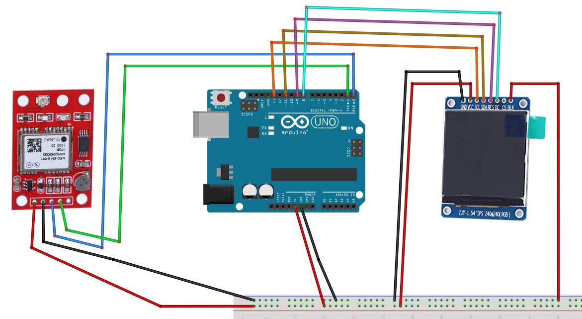
- Connect Arduino 5V to GPS module VCC
- Connect Arduino GND to GPS module GND
- Connect GPS module RX to Arduino TX
- Connect GPS module TX to Arduino RX
- Connect Arduino 5V to LCD pin VCC
- Connect Arduino 5V to LCD pin BLK
- Connect Arduino GND to LCD pin GND
- Connect LCD pin SCL to Arduino digital pin 13
- Connect LCD pin SDA to Arduino digital pin 11
- Connect LCD pin Reset to Arduino digital pin 9
- Connect LCD pin DC to Arduino digital pin 8
Start Visuino, and Select the Arduino UNO Board Type
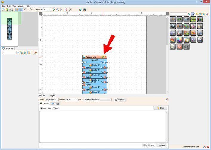
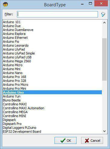
The Visuino: https://www.visuino.eu also needs to be installed. Download Free version or register for a Free Trial.
Start Visuino as shown in the first picture Click on the "Tools" button on the Arduino component (Picture 1) in Visuino When the dialog appears, select "Arduino UNO" as shown on Picture 2
In Visuino Add Components
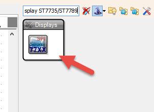
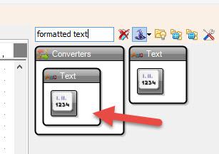
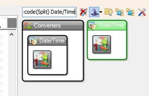
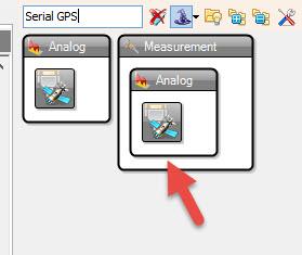
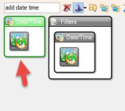
- Add "Serial GPS" component
- Add "Decode(Split) Date/Time" component
- Add "Add Date/Time" component
- Add 2X "Formatted Text" text
- Add "TFT Color Display ST7735/ST7789" component
In Visuino Set Components
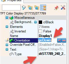
- Select "Display1" and in the properties window set Orientation to goDown, Type to dtST7789_240_240
- Double click on the "Display1"
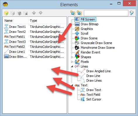
In the Elements window:
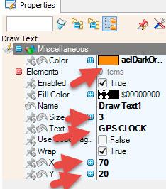
- Drag "Draw Text" to the left
In the properties window set Color to aclDarkOrange, size to 3, Text to "GPS CLOCK", X to 70, Y to 20
- Drag "Draw Text" to the left
In the properties window set size to 2, Text to "Time:", Y to 90
- Drag "Text Field"
In the properties window set Color to aclTurquoise, size to 3, X to 70, Y to 90
- Drag "Draw Text"
In the properties window set size to 2, Text to "Date:", Y to 140
- Drag "Text Field"
In the properties window set Color to aclTurquoise, size to 3, X to 70, Y to 140
- Drag "Draw Line"
In the properties window set Height to 0, Width to 240, Y to 70
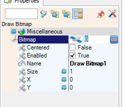
- Drag "Draw Bitmap" to the left
In the properties window select bitmap and click on the 3 dots and in the bitmap editor load the bitmap file (included here)
Note: you can get other bitmaps here
- Close the Bitmap Editor
- Close the Elements window
- Select "FormattedText1" and in the property window set text to %0:%1:%2
- Double click on the "FormattedText1" and in the elements window drag 3X "Text Element" to the left
Close the Elements window
- Select "FormattedText2" and in the property window set text to %0:%1:%2
- Double click on the "FormattedText2" and in the elements window drag 3X "Text Element" to the left
Close the Elements window
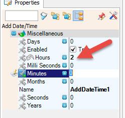
To adjust the time zone select "AddDateTime1" and in the property window change hours to your time zone, example hours: 2 ,this will add 2h to the time received from the satellite.
In Visuino Connect Components
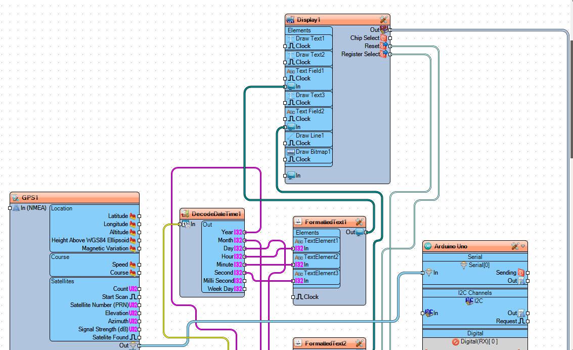
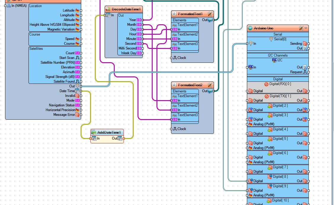
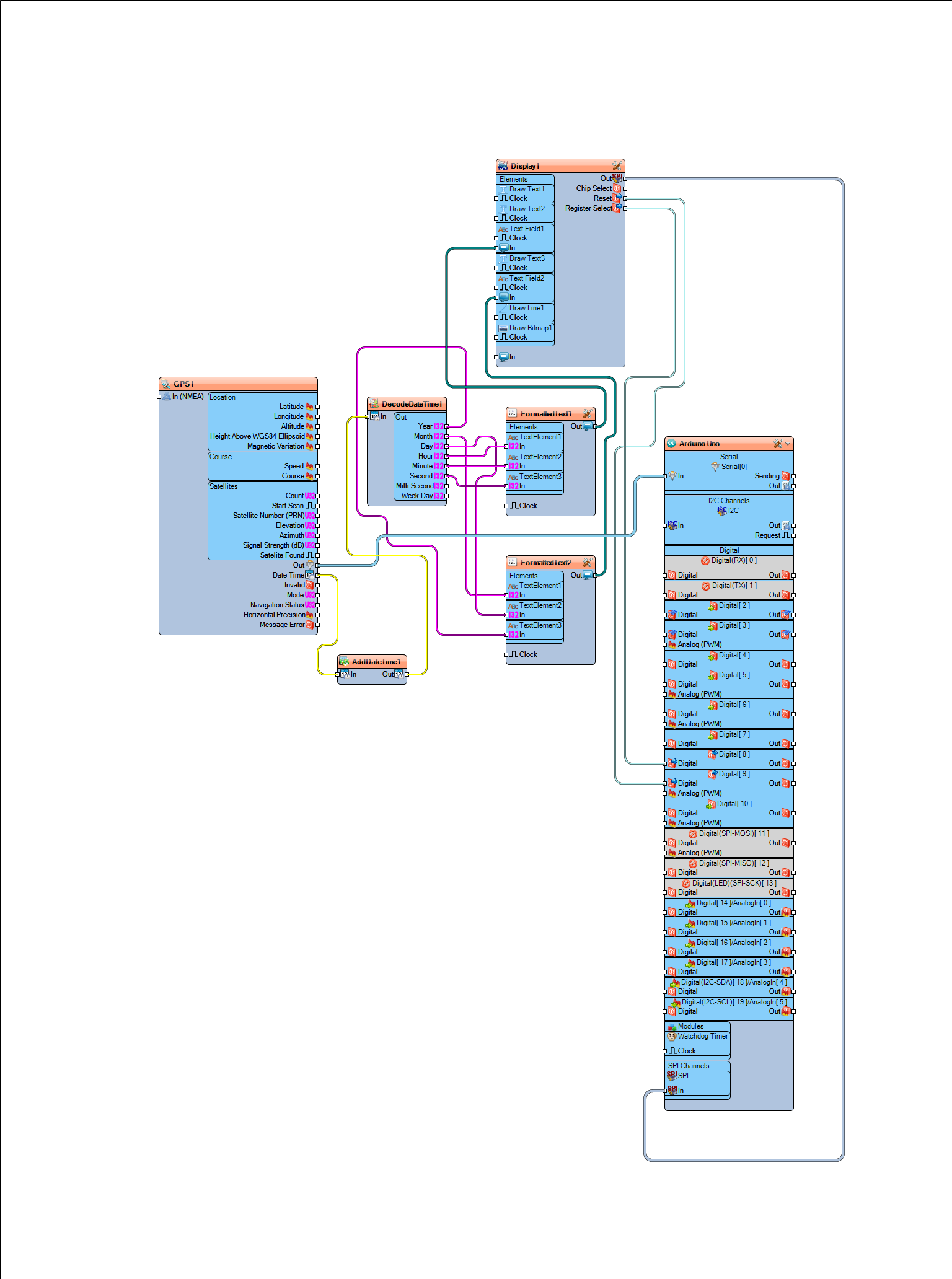
- Connect Display1 pin Out SPI to Arduino board pin SPI In
- Connect Display1 pin Reset to Arduino board digital pin 9
- Connect Display1 pin Register Select to Arduino board digital pin 8
- Connect GPS1 pin Date time to AddDateTime1 pin In
- Connect AddDateTime1 pin Out to DecodeDateTime1pin In
- Connect GPS1 pin Out to Arduino board pin Serial[0] In
- Connect DecodeDateTime1 pin Year to FormattedText2 pin Text Element3 In
- Connect DecodeDateTime1 pin Month to FormattedText2 pin Text Element1 In
- Connect DecodeDateTime1 pin Day to FormattedText2 pin Text Element2 In
- Connect DecodeDateTime1 pin Hour to FormattedText1 pin Text Element1 In
- Connect DecodeDateTime1 pin Minute to FormattedText1 pin Text Element2 In
- Connect DecodeDateTime1 pin Second to FormattedText1 pin Text Element3 In
- Connect FormattedText1 pin Out to Display1Text Field1 pin In
- Connect FormattedText2 pin Out to Display1Text Field2 pin In
Before Uploading to Arduino
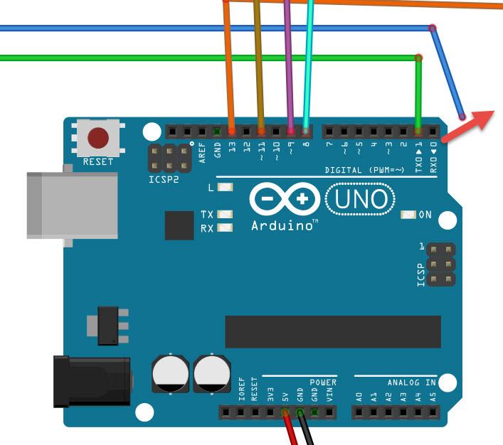
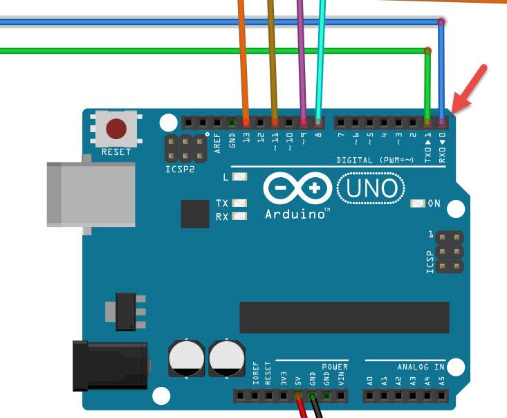
- Before you upload to Arduino disconnect the RX pin on the Arduino
- After the upload connect the wire back to Arduino pin RX
Generate, Compile, and Upload the Arduino Code

In Visuino, at the bottom click on the "Build" Tab, make sure the correct port is selected, then click on the "Compile/Build and Upload" button.
Play
If you power the Arduino UNO module, the Display will start to show the time and date acquired from the satellites.
Congratulations! You have completed your project with Visuino. Also attached is the Visuino project, that I created for this Instructable, you can download it and open it in Visuino: https://www.visuino.eu
File GPS-SAT-TIME.visuino (Project with a zone adjustment)
File GPS-TIME2.visuino (Project without zone adjustment)