Arduino English Language Assistant
by rdcannon349 in Circuits > Arduino
747 Views, 1 Favorites, 0 Comments
Arduino English Language Assistant
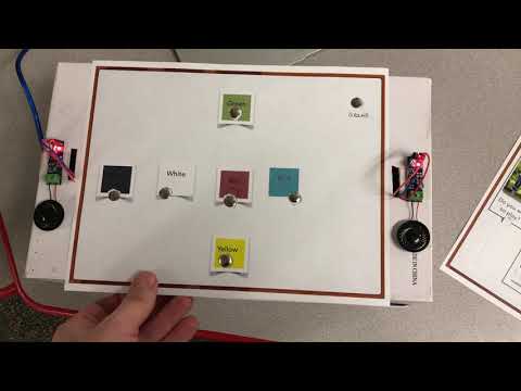
Introduction:
I am a grad student working toward my Master's Degree in Education with a focus on Technology Integration. I currently teach music and have spent a good part of this semester learning about using the Arduino for music-related projects. For my final project, I wanted to try something that could be used outside of the music classroom. I talked with the ELL teacher in my school who works with kindergarten, and she discussed the need for vocabulary reinforcement, so I wanted to create a language assistant.
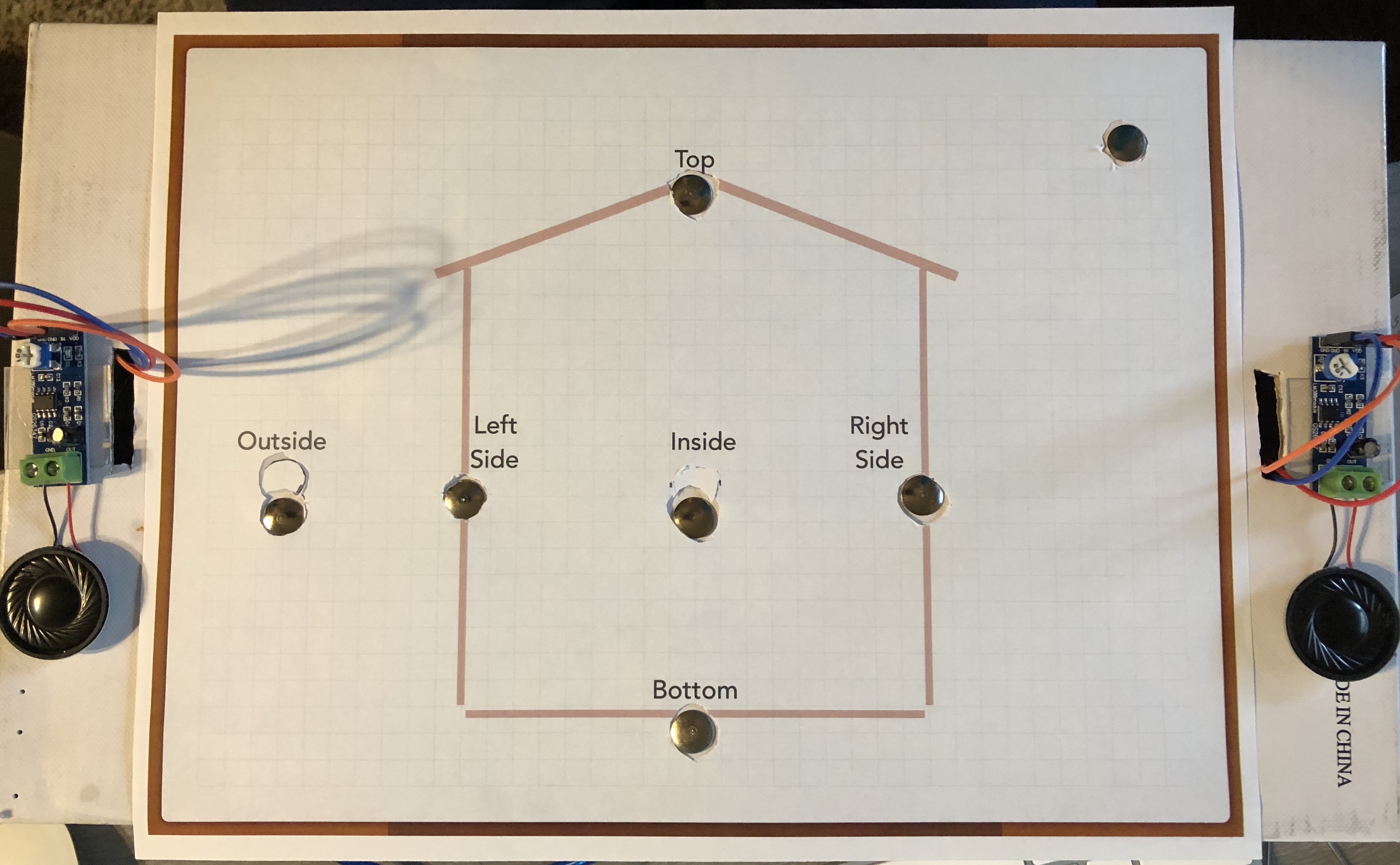
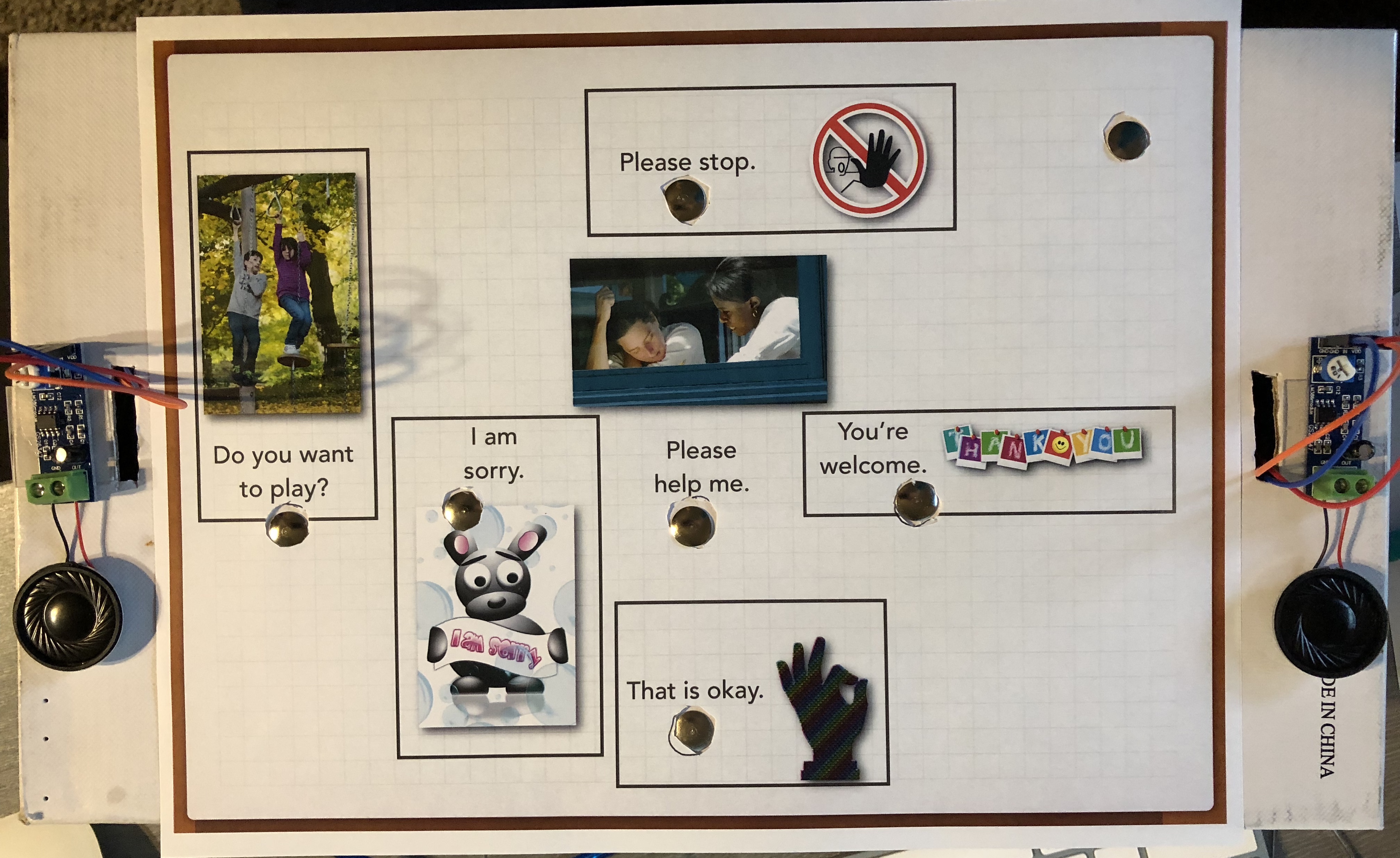
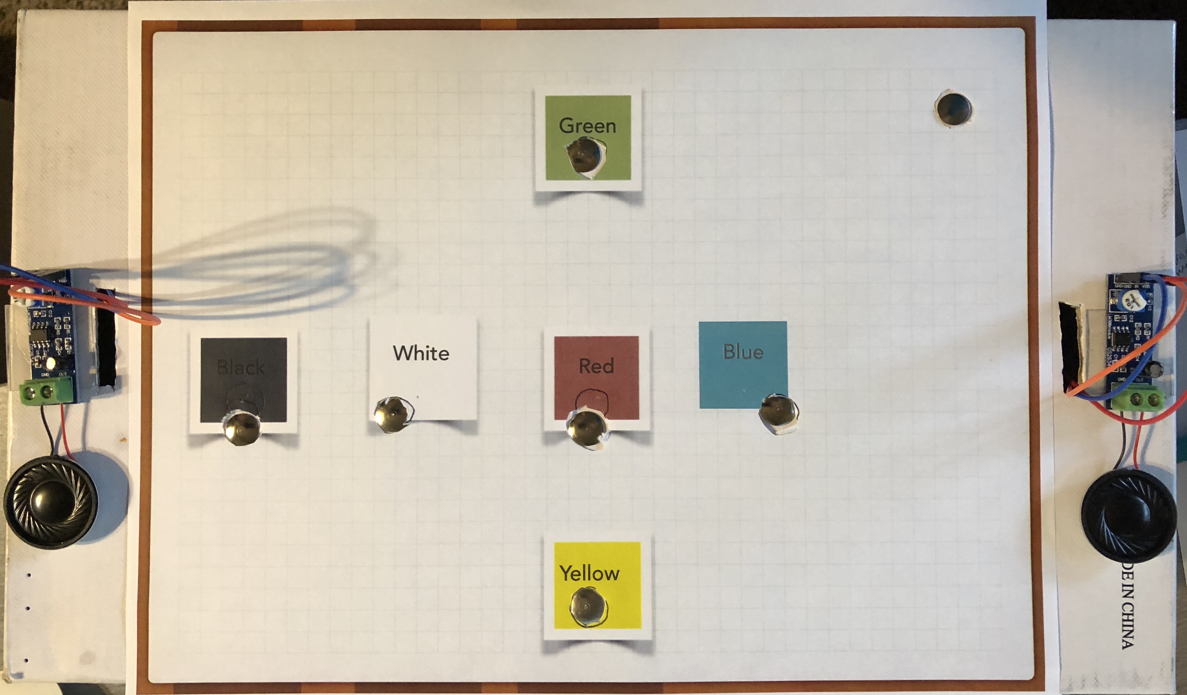
Using concepts from the Fruit + Electronics = Piano (2016), and Fun with Talking Arduino (n.d.), I was able to create this device which could be used to reinforce or assess a student's understanding of the vocabulary words and phrases. This project uses six capacitive touch sensors. When the sensor and the ground are touched, the device will speak the word or phrase assigned to that sensor. The sketch has three functions available to allow the user the opportunity to easily change from one vocabulary set to another. I have also included printouts that can be placed on top of the device for ease of use. Check out the video to see a more in-depth description of the product!
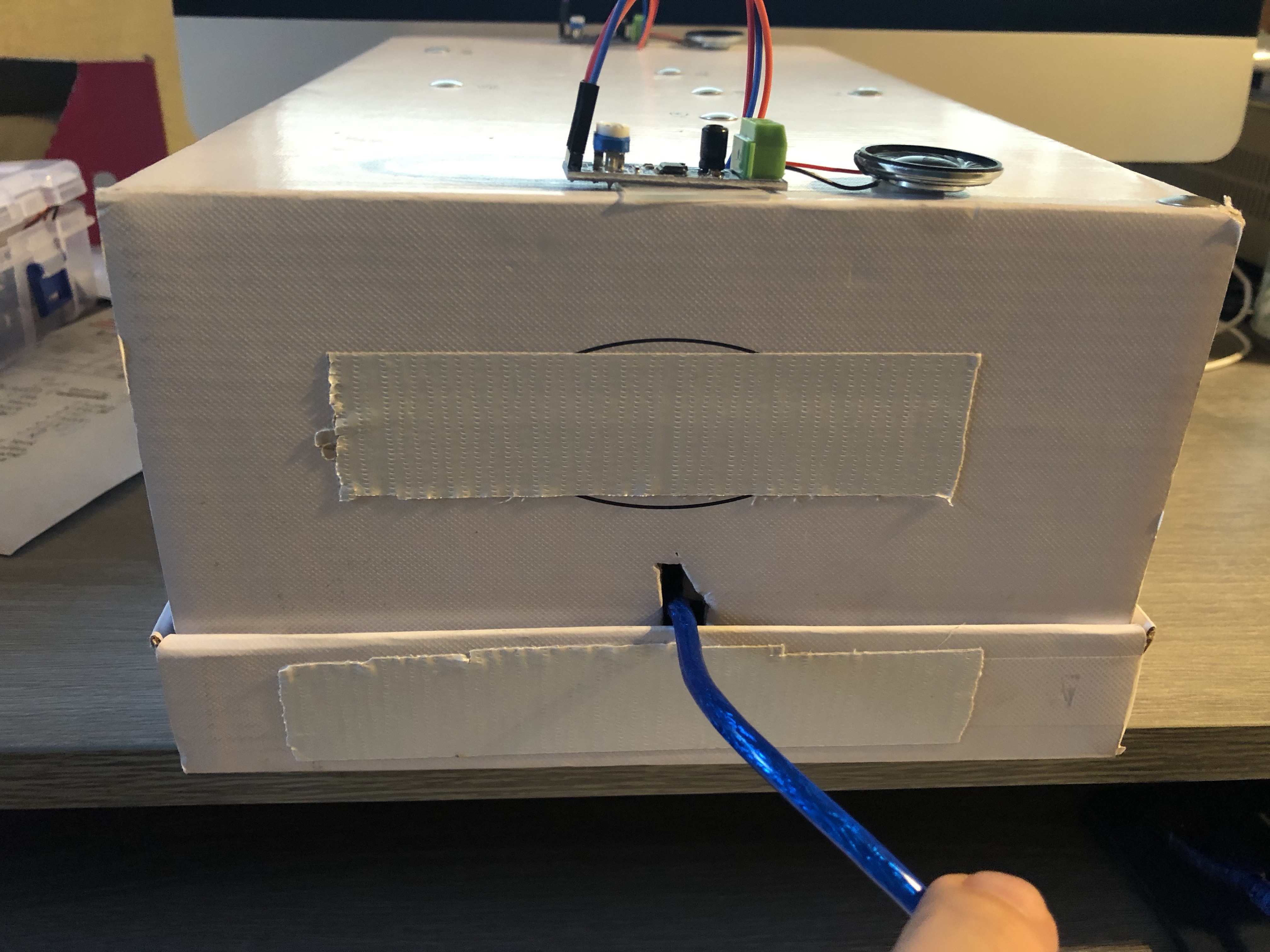
The unit is housed inside of an inverted shoe box. The Arduino is mounted to the inside lid of the box and the "top" of the unit is the bottom of the shoe box. I cut holes in the "top" of the unit as well as one on the side for wiring speakers and the USB cable. Any extra duct tape you might see is only to cover the brand name of the shoe.
Skill Level: Intermediate, as talkie needs to be downloaded and adjusted to fit the needs of the device.
References:
Fruit + Electronics = Piano. (2016). Retrieved from https://www.bigmessowires.com/2016/08/19/fruit-ele...
Fun with talking Arduino. (n.d.). Retrieved from https://rimstar.org/science_electronics_projects/a...
Materials:
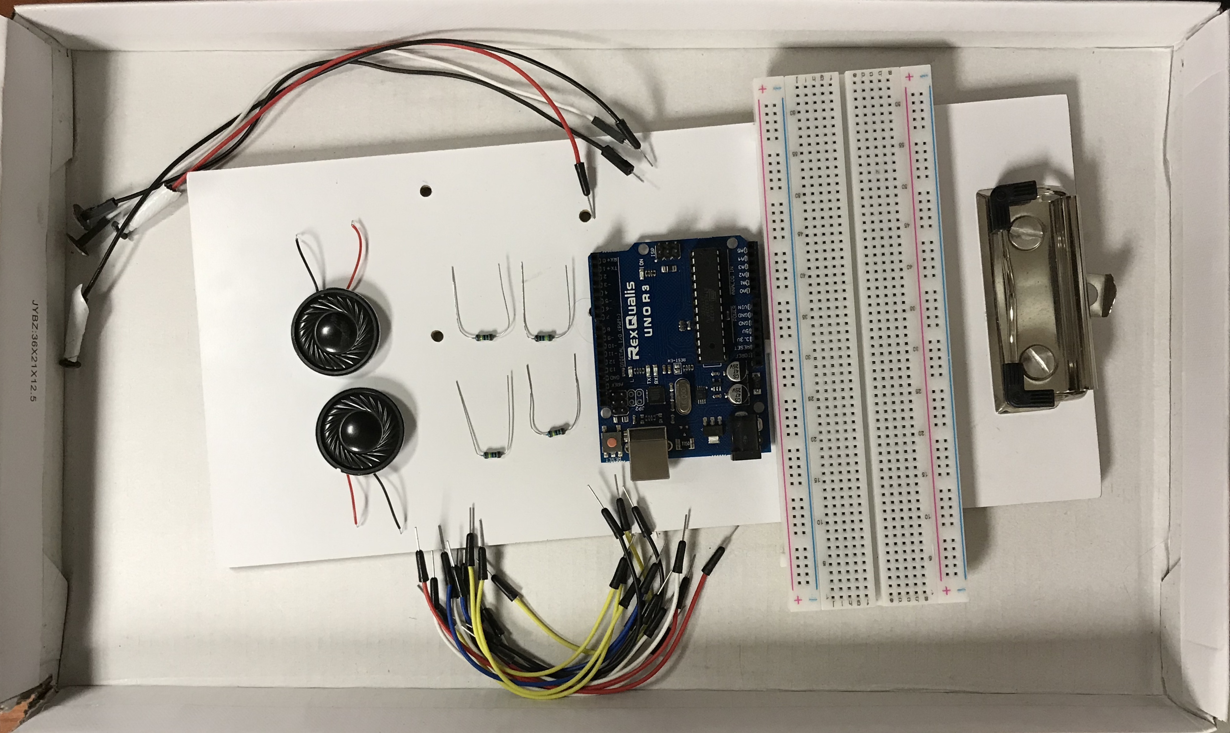
Arduino Components:
1 Arduino Uno / USB cable
1 Breadboard
6 1 Mega Ohm Resistors
2 speakers (I used 2 8 Ohm, 2 Watt speakers)
2 amplifiers (I used 2 LM386 modules)
19 Male - Female Cables
14 Male - Male Cables (various lengths)
Tools:
7 Thumbtacks (must be all metal, the painted ones don't seem to work as well)
1 Shoebox (for the case)
4 Coated Paper Clips (to mount Arduino to clipboard, optional)
3 piece of paper and color printer to print presentation pages
Double Stick Tape (Optional)
Duct Tape
Small Screwdriver (I used an eyeglasses screwdriver, but a Phillips head will also work)
Schematic
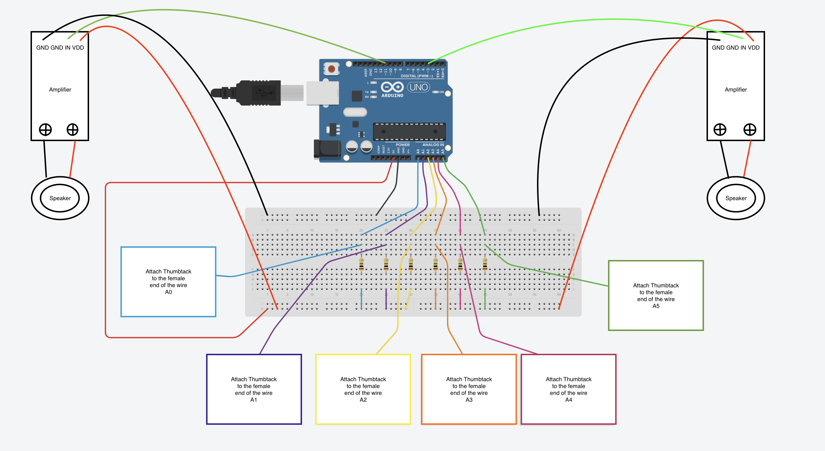
Here is the schematic for the device. I used Tinkercad to create the basic schematic, then adjusted the image to compensate for the devices that were not on the Tinkercad menu. I added a second male-female wire to each connection from the Arduino to the Amplifier, which allowed me to open and close the box to make the other connections.
Recommendation: do not push the thumbtack into the female end of the wire until you make the final connections through the shoe box. The thumbtacks will stretch the connections on the female end of the wire, causing a reduced connection if removed and re-installed. I ended up duct taping the wires to the inside of the box during the final install to compensate for the stretching of the inputs after testing the unit.
References:
Tinkercad. (2019). Retrieved from https://www.tinkercad.com/things/2NU1HTyLe2v-foil-...
Step 1: Prepare You Work Surface (optional)
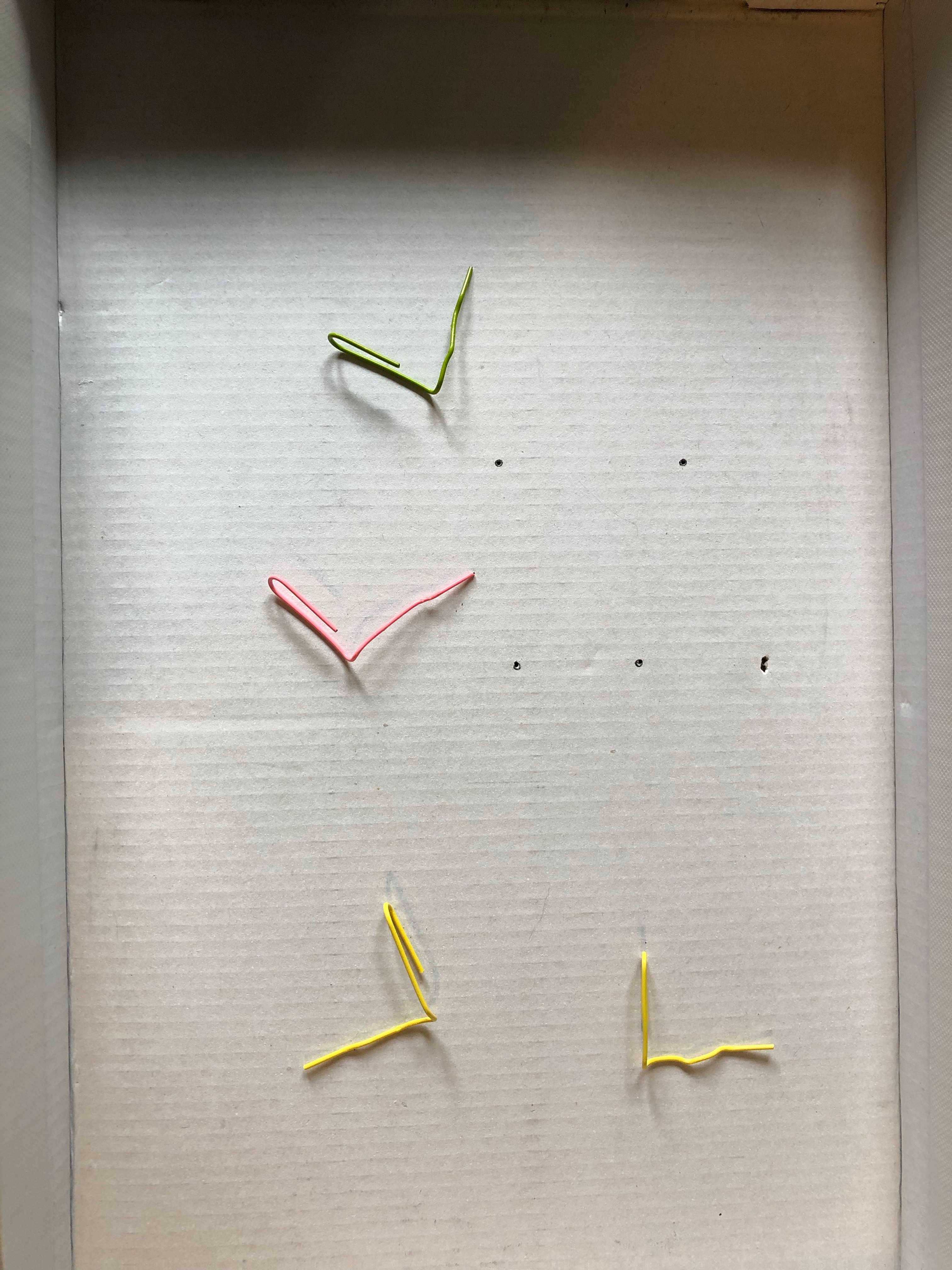
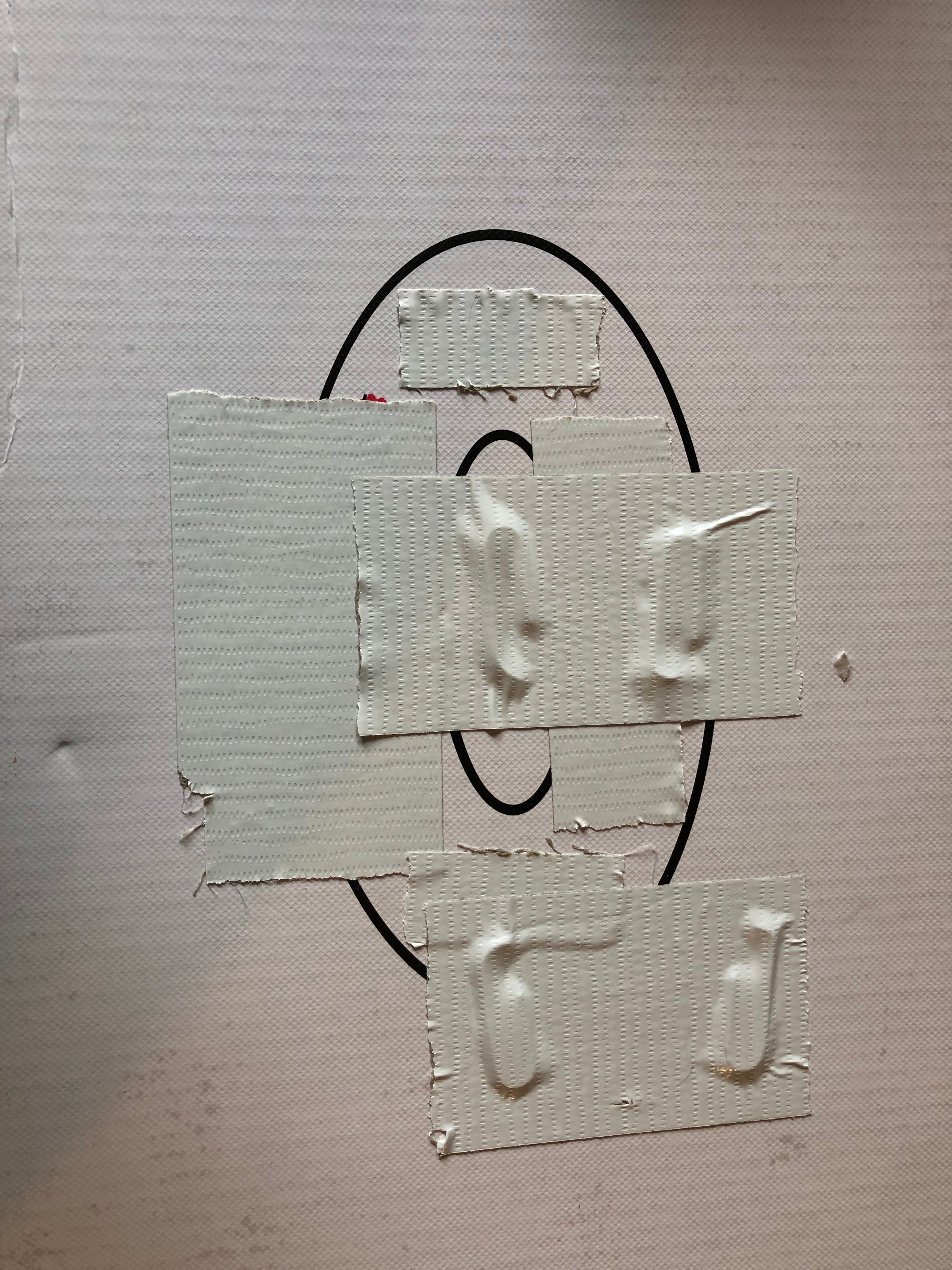
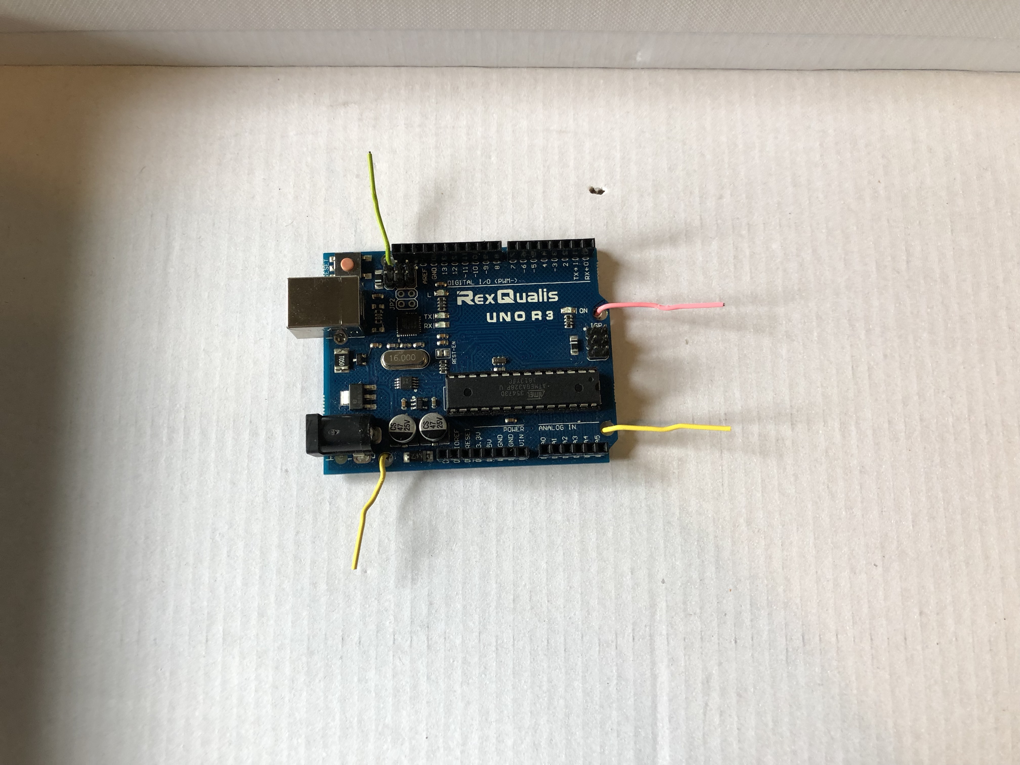
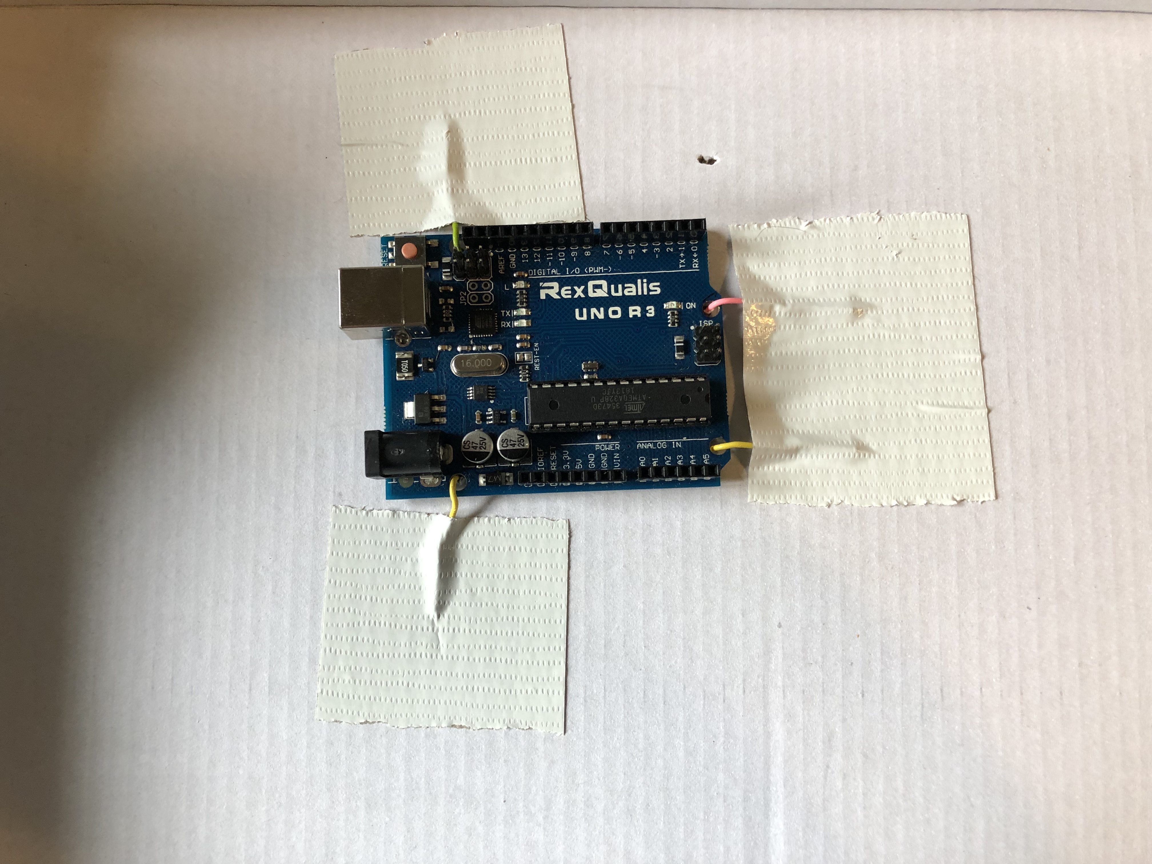
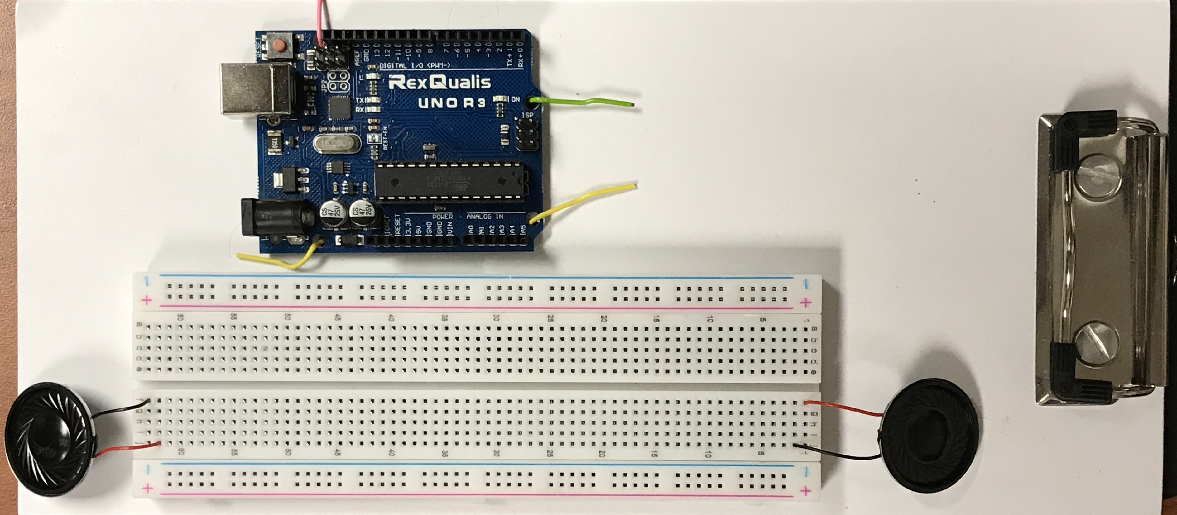
I don't want my Arduino shifting around when transported, so I decided to mount mine to the inside lid of the shoe box. Using the screw holes on the Arduino Uno, I marked the shoe box lid and poked holes through it. I unwound the outer part of the paper clips (see diagram 1) and pushed them through the holes from the outside of the box lid, then used duct tape to hold them in place (see diagram 2).
After flipping the box lid over (to the inside of the box), I carefully placed the paper clips through the screw holes on the Arduino and bent the paper clips down (see diagram 3) and duct taped the paper clips in place. Finally, using double stick tape, I mounted the breadboard to the box lid (see diagram 4).
Again, this step is optional, but for me, I found the unit traveled better when mounted. The wires were less likely to disconnect.
Step 2: Connect Speakers
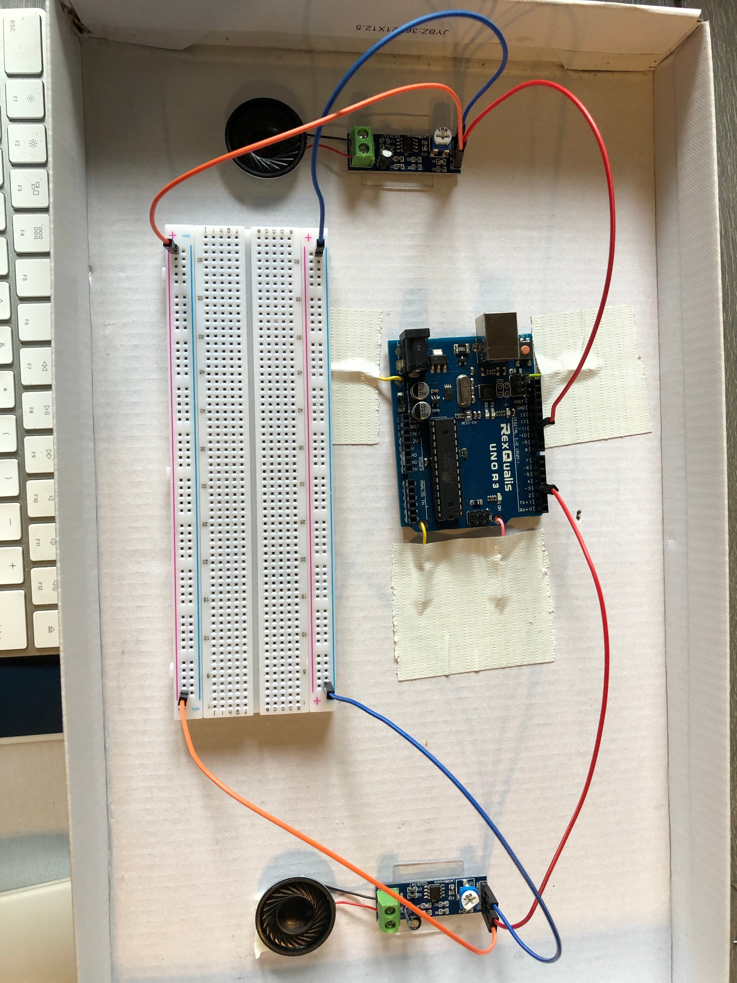
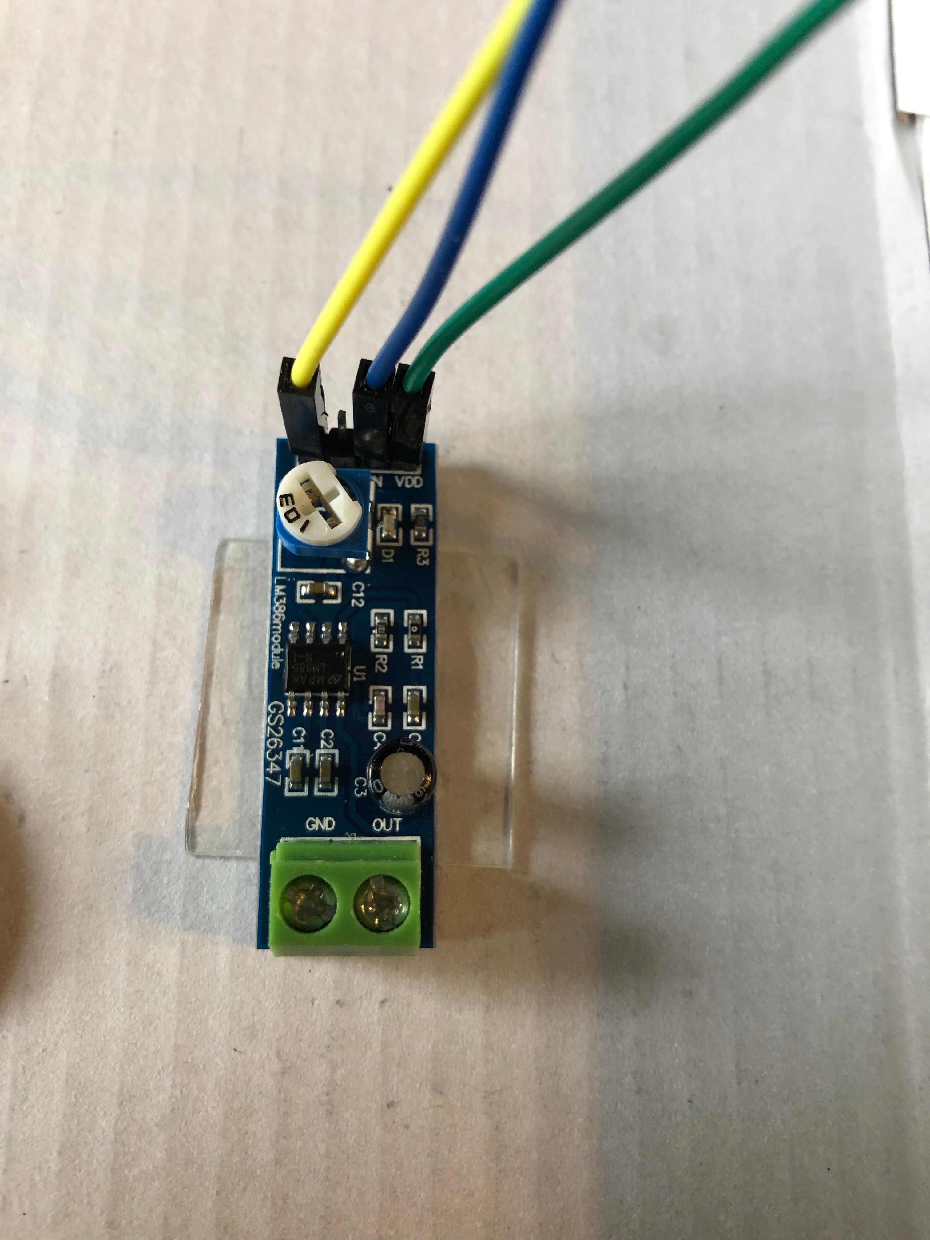
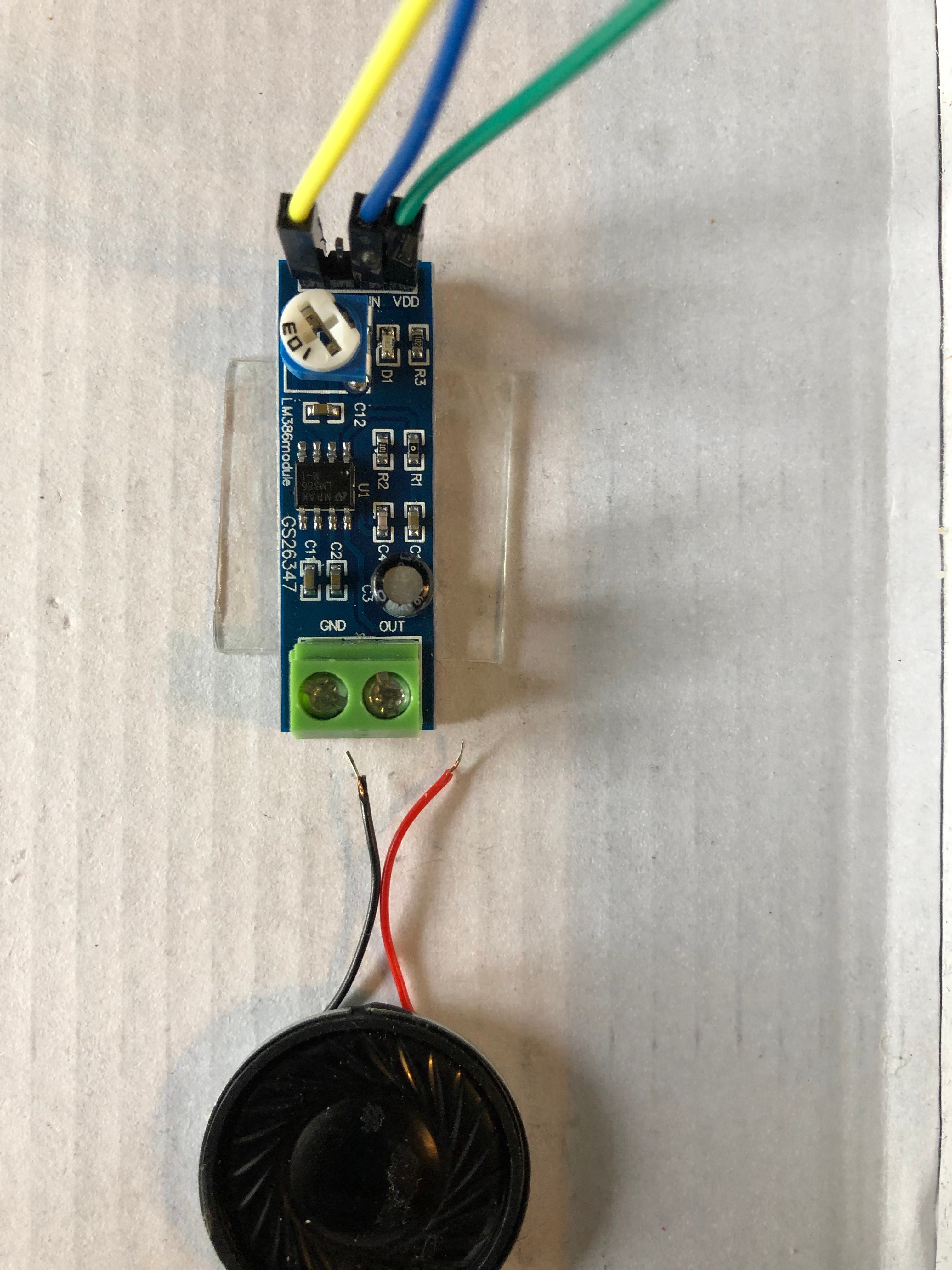
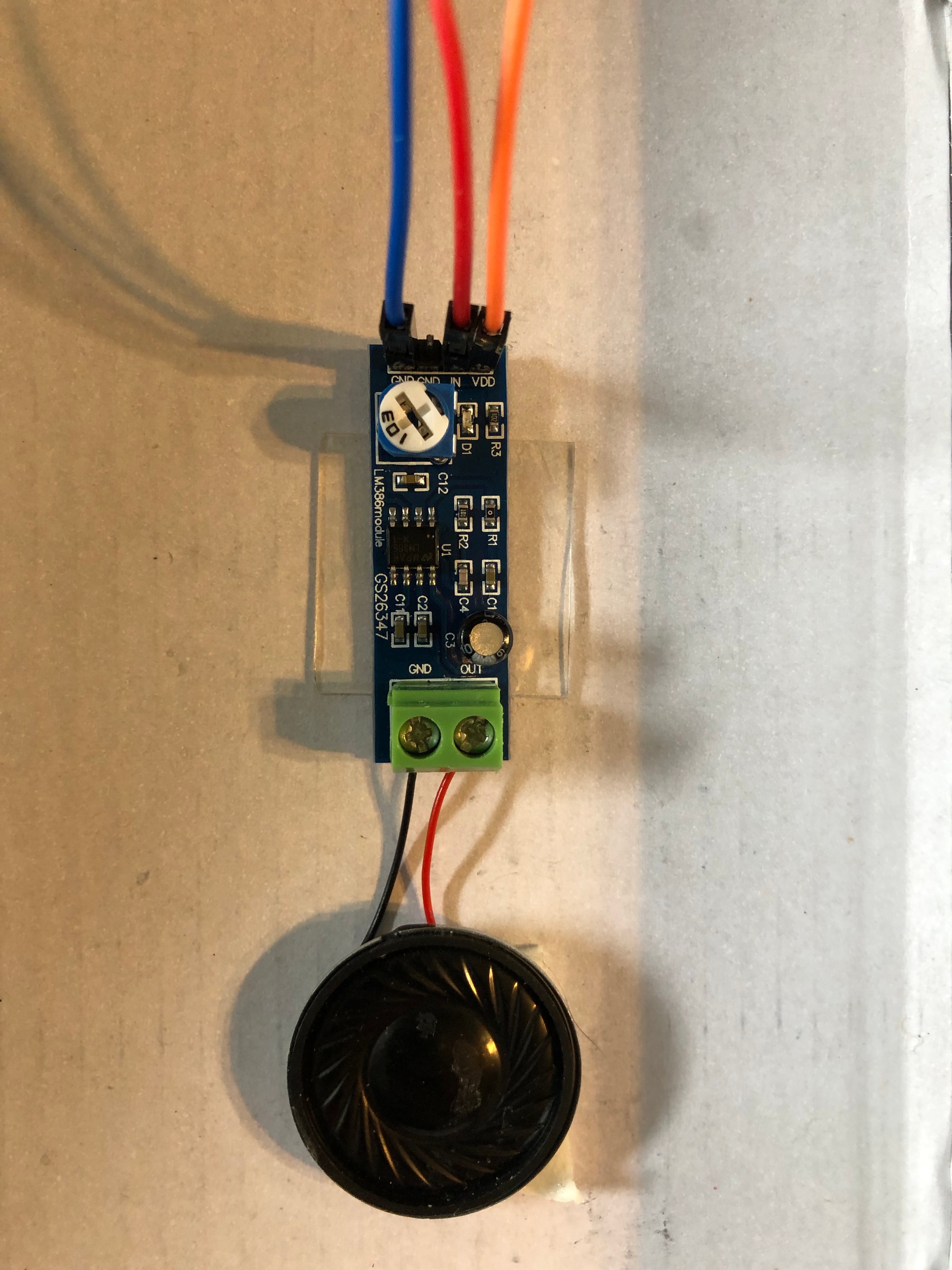
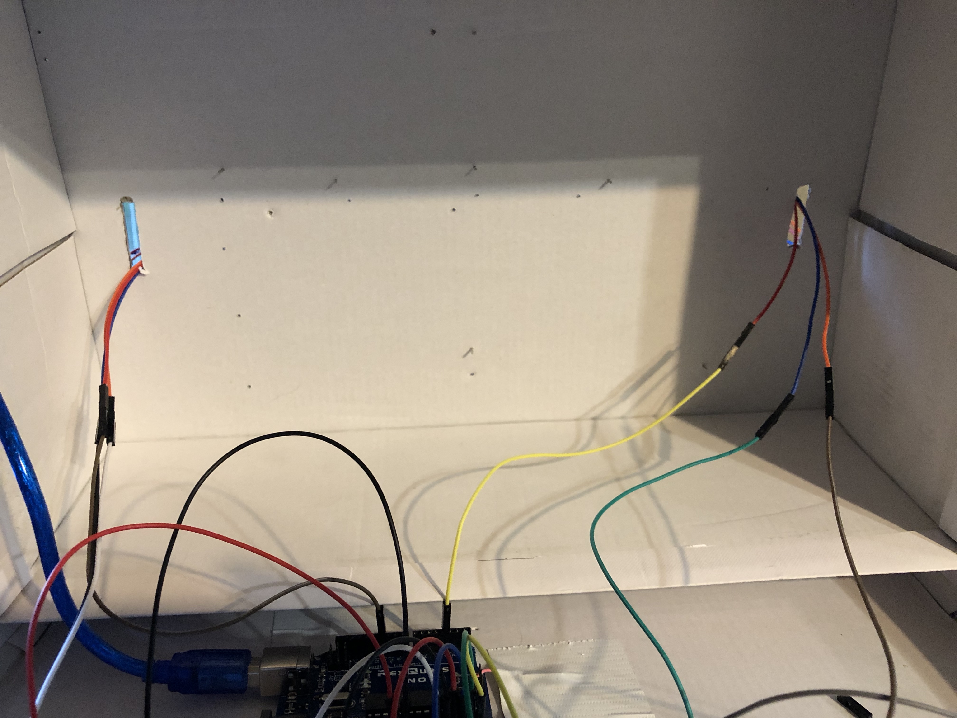
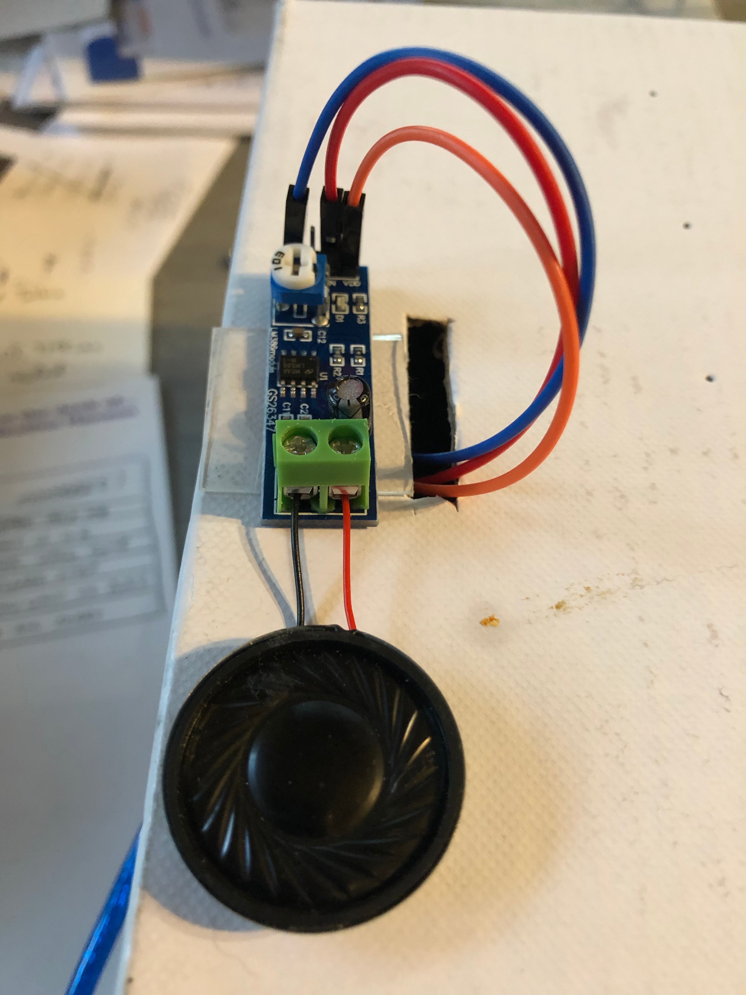
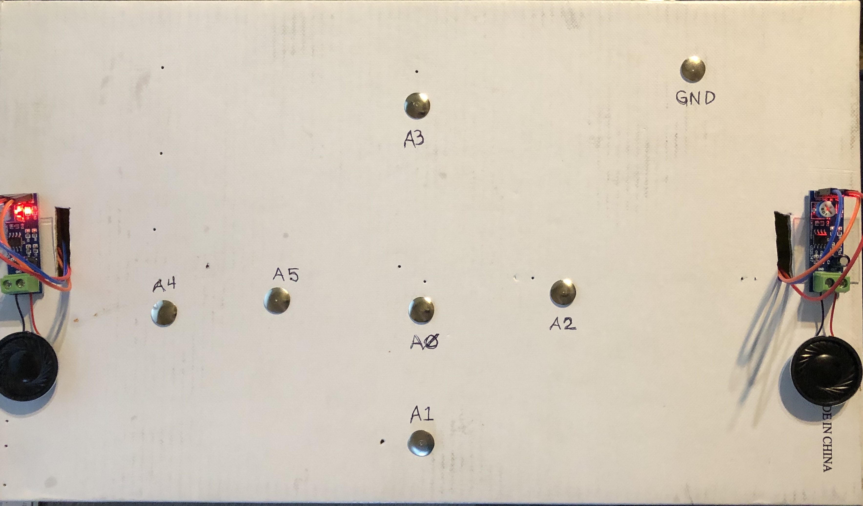
This is where I would consider changing my plan. I used speakers that I have, but in the future would replace them with better quality speakers with longer wires (Word to the wise, don't cheap out on the speakers). The device sounds much better when I put the speakers on the outside, but the amplifiers were hanging, which caused the wires to disconnect. So, for my Tim Gunn "Make it work" moment, I added an extra male to female wire to each of the speaker connections wires, tucked them through a hole I cut in the top of the unit and tucked the wires through before connecting them to the amplifier.
On the amplifier, there are four pins marked "GND", "GND", "IN", and "VDD". Connect the female ends of the wires to the first "GND" pin (I used blue), the "IN" pin (I used red) and the "VDD" pin (I used orange). Repeat the process with the other speaker.
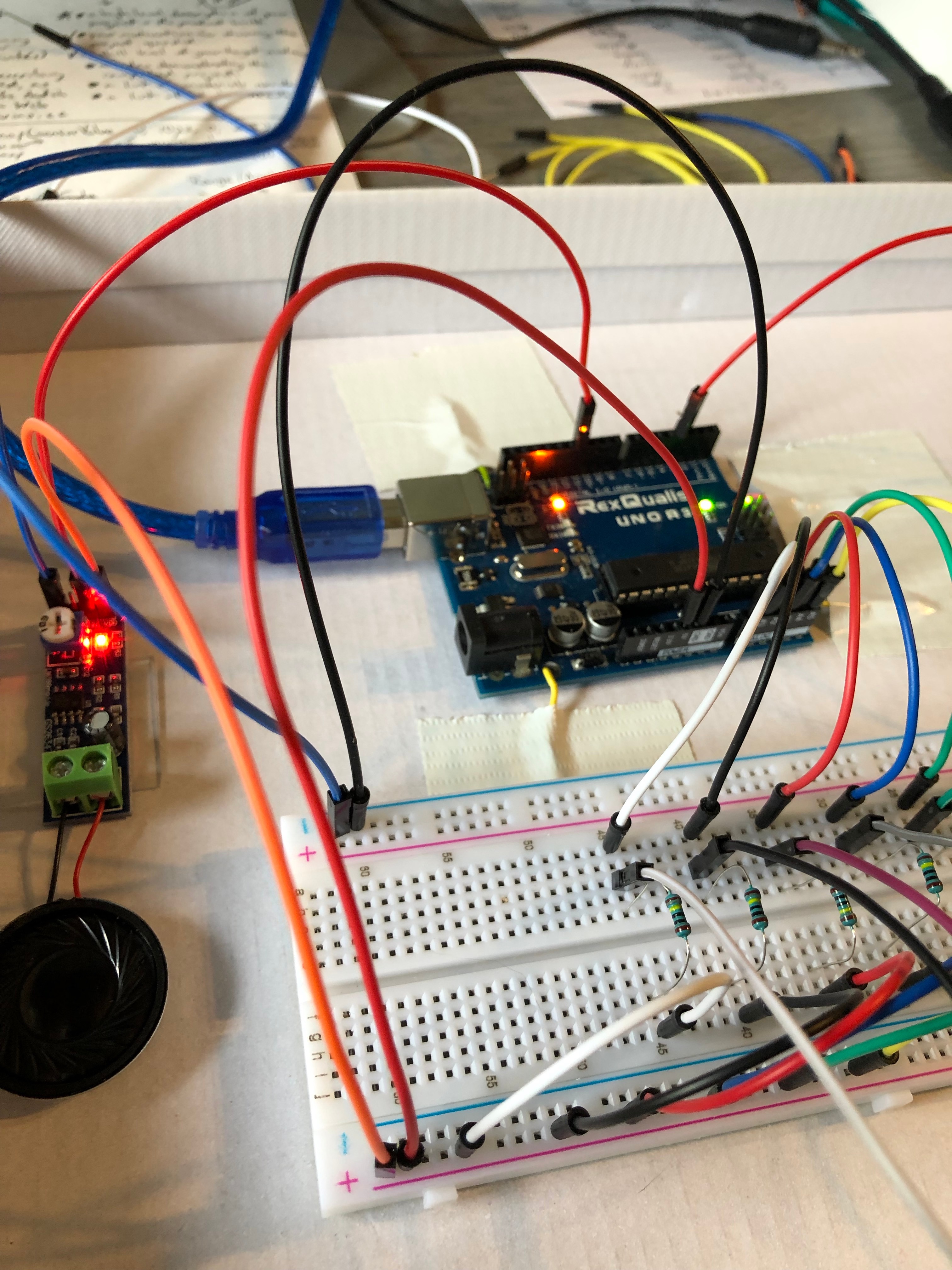
Plug the male end of the wires into the breadboard and Arduino - GND(blue) to the negative bar on the breadboard, IN(red) to the Arduino pins 3 and 11, and VDD(orange) to the positive bar on the breadboard.
On the amplifier, loosen the two screws marked "GND" and "OUT". Insert the black speaker wire into "GND" and the red speaker wire into "OUT" and tighten the screws. I then double stick taped them to the outside of the unit.
Step 3: "Analog In" Wiring
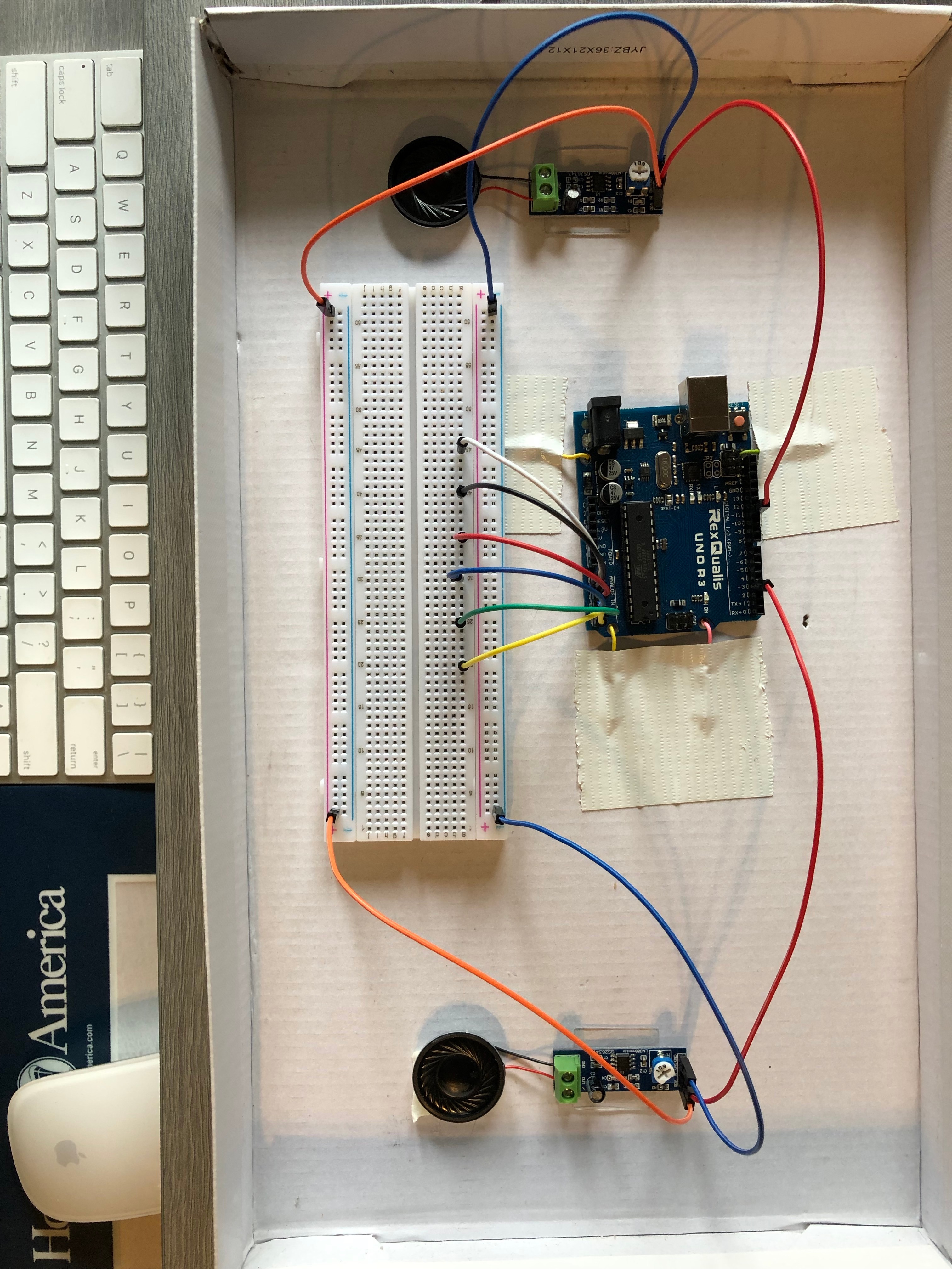
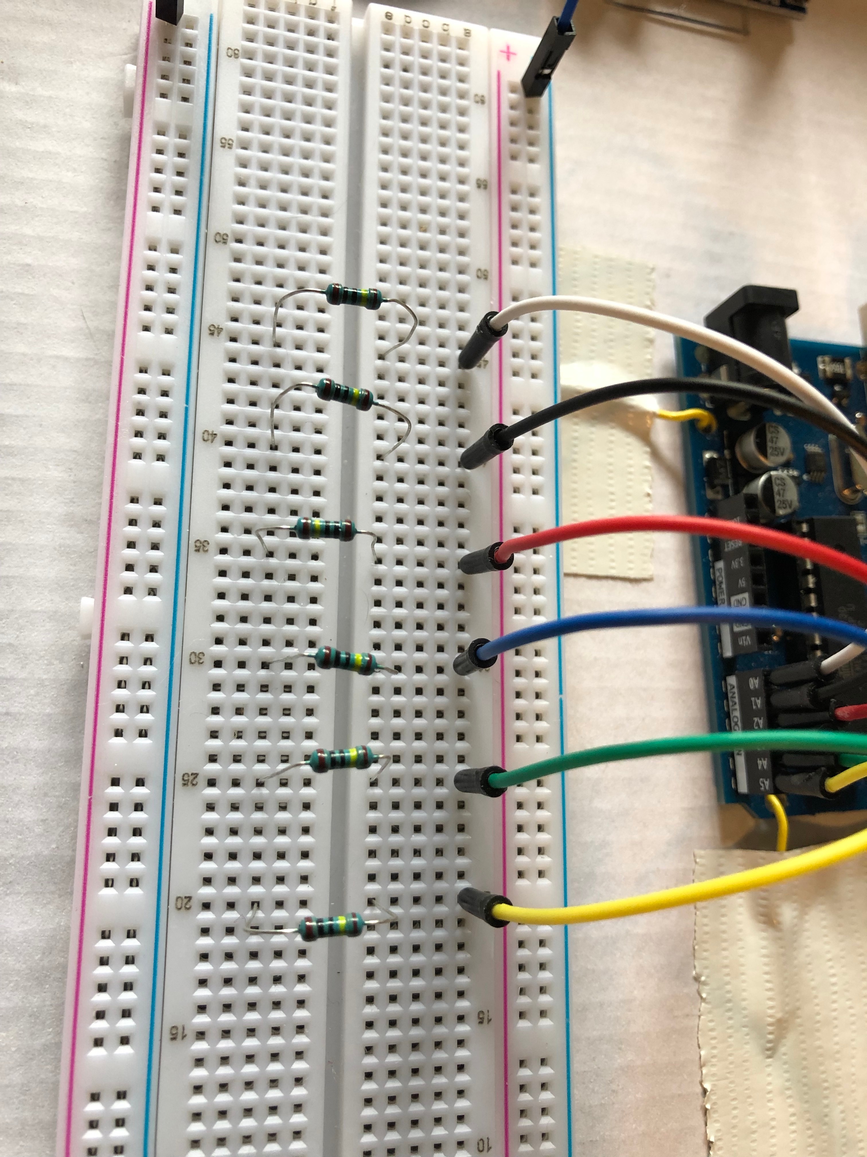
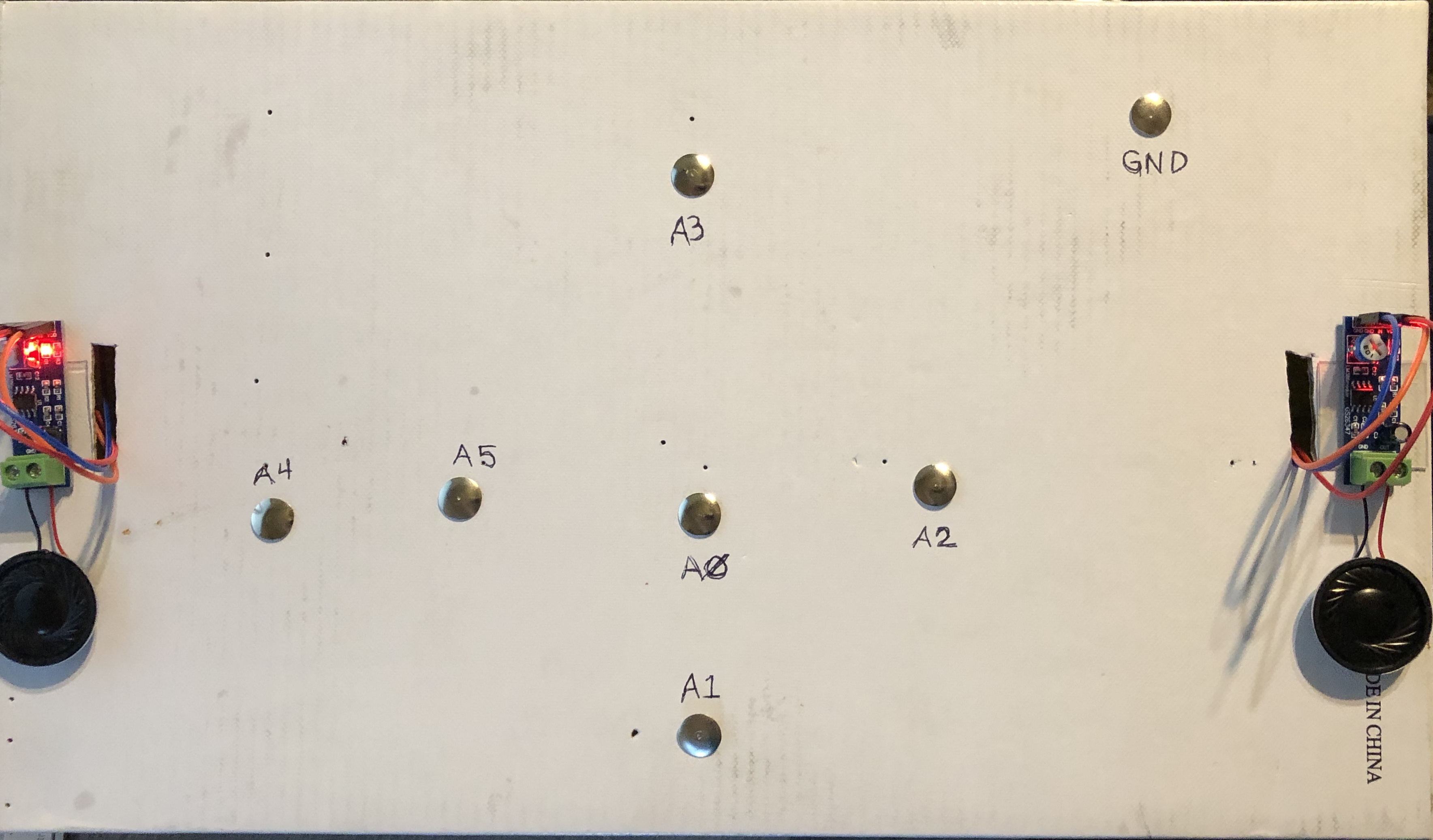
From your Arduino, plug a male to male wire into each of the pins (A0 - A5). Plug the other end into the breadboard (diagram 1 - I placed them five rows apart for better visualization since all of my wire colors do not match).
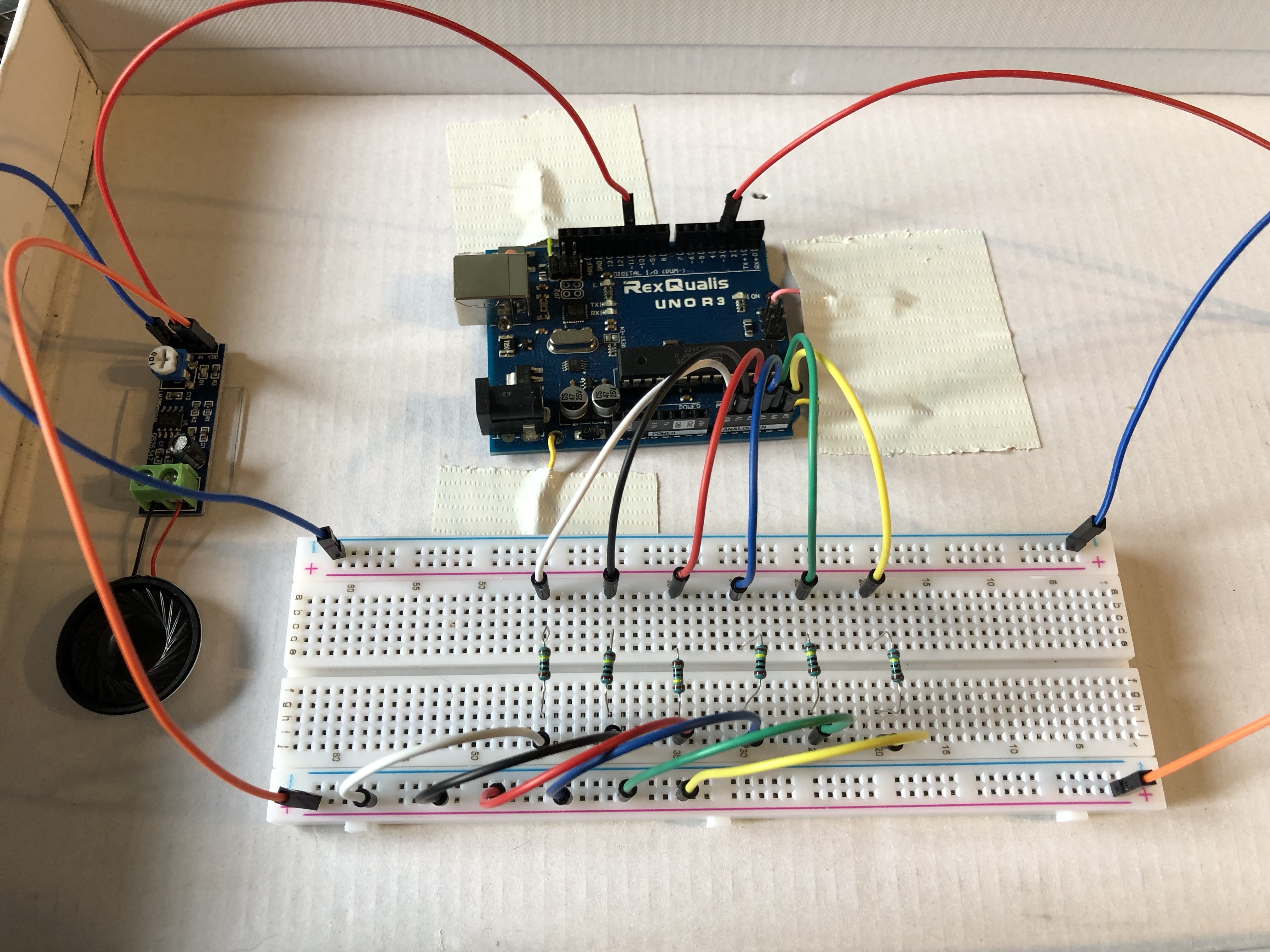
Use the 1 Mega Ohm resistors to cross the board (one end on each side of the center line), leaving space for the sensor wire to be inserted between the wire and the resistor (diagram 2 - I went from column e to column h).
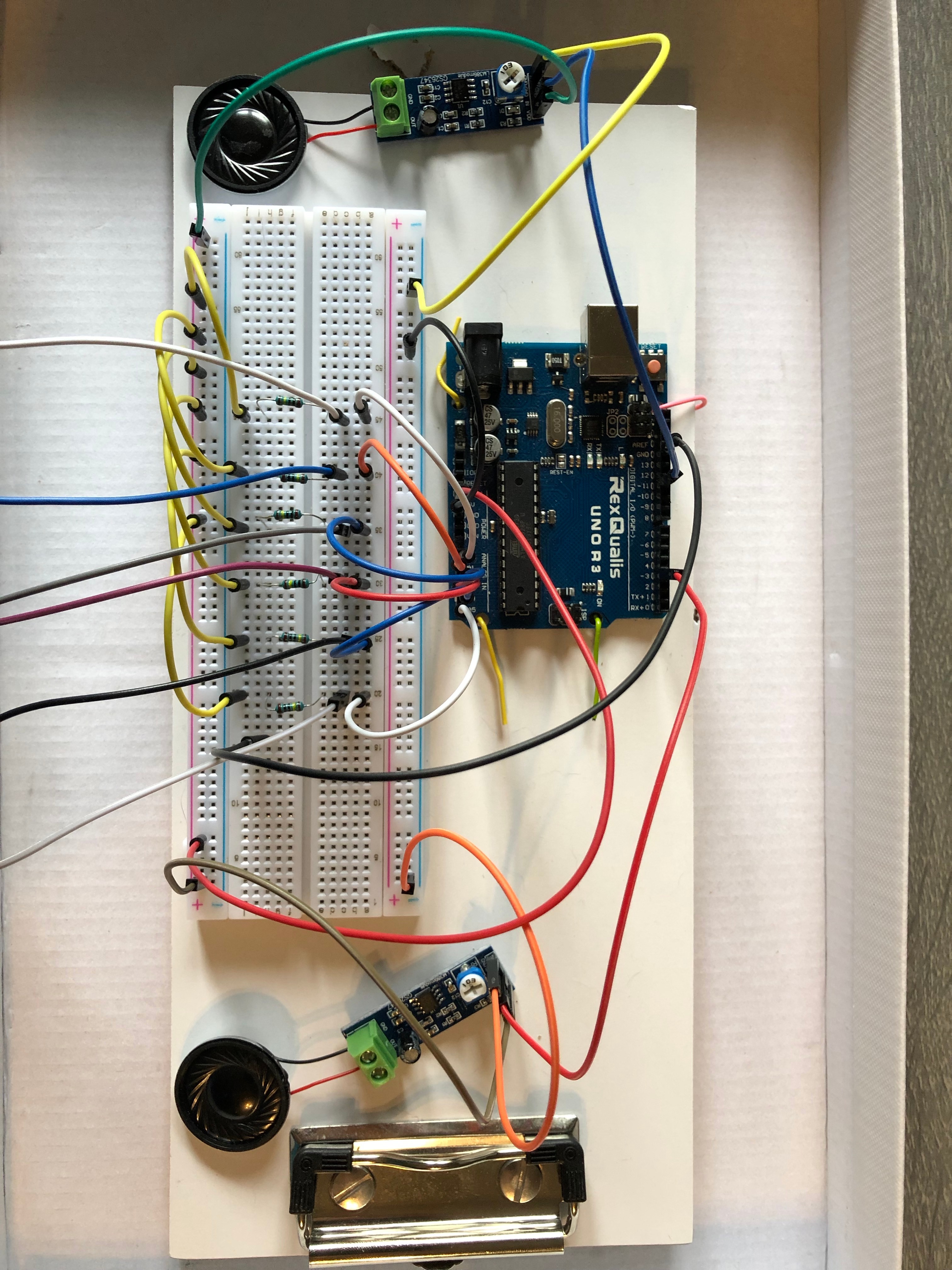
Using another set of male to male wires, connect the resistor rows (column j) to the positive strip (diagram 3).
Connect a wire from the positive strip to the 5V pin on the Arduino, and a wire from the negative strip to the GND pin on the Arduino (diagram 4 shows all of the wirings, including the speakers).
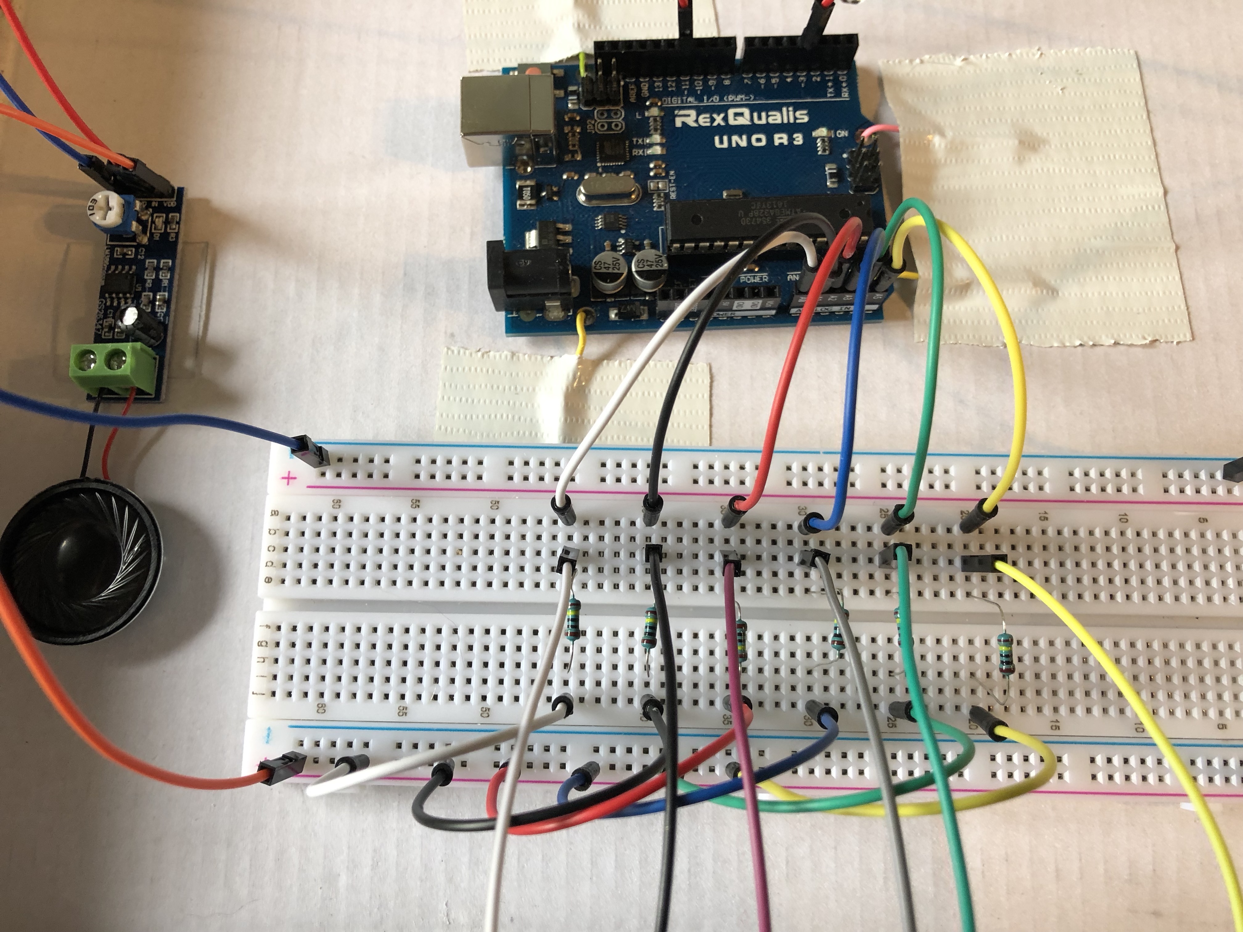
Finally, plug a male-female wire between the initial wire (to analog in) and the resistor (diagram 5).
Step 4: the Sketch


Before running the sketch, you will need to download Talkie from GitHub. When the download is complete, you will need to open the folder "going-digital-Talkie-7f57628". Open the folder called "Talkie", go to the folder called "Examples", then the folder marked "Vocab_US_TI99", then open "Vocab_US_TI99.ino". This will open the library where you can adjust the words you wish to use.
(About Talkie library// Copyright 2011 Peter Knight// This code is released under GPLv2 license. // The following phrases are derived from those built into the Texas Instruments TI99/4A Speech System add-on from 1979. A deep male voice with a southern USA accent.)
The library is too large to run on the Arduino, so they recommend only activating words you will use in your sketch. To activate a word, delete the // from before the word you wish to activate (ex. uint8_t spAM[]). To deactivate, just add the // back before the word you do not wish to use (ex. //uint8_t spANSWER[]).
Here is the list of words you will need to activate for this sketch: Am, Black, Blue, Bottom, Come, Do, Green, Help, I, In, Is, K, Left, Me, O, Out, Play, Please, Red, Right, Side, Sorry, Stop, That, To, Top, Want, Well, White, Yellow, You, Your.
Then, add this sketch to your Arduino Editor. I used the Arduino download instead of the web editor for this sketch because of the Talkie library download.
There are three functions in this sketch (house, color, manners), each containing its own set of vocabulary words. To activate a function, simply erase the two // before the function name. Don't forget to deactivate the other two functions by adding the // before the function names. Doing this will deactivate the function by turning it into a comment. See image above or watch how to change the functions on the demonstration video at the beginning of the instructable.
The sketch uses capacitive touch, treating the thumbtacks as sensors. Touching the sensor and the ground allows your body to complete the circuit, making the device speak using analogRead and voice.say.
References:
Talkie. (n.d.). Retrieved from https://github.com/going-digital/Talkie
Step 5: Finishing Touches
I cut a hole in the side of the box for the USB cable, plugged the cable into the Arduino, then fed the remaining cable through the hole, which will be plugged into the computer when ready to use.
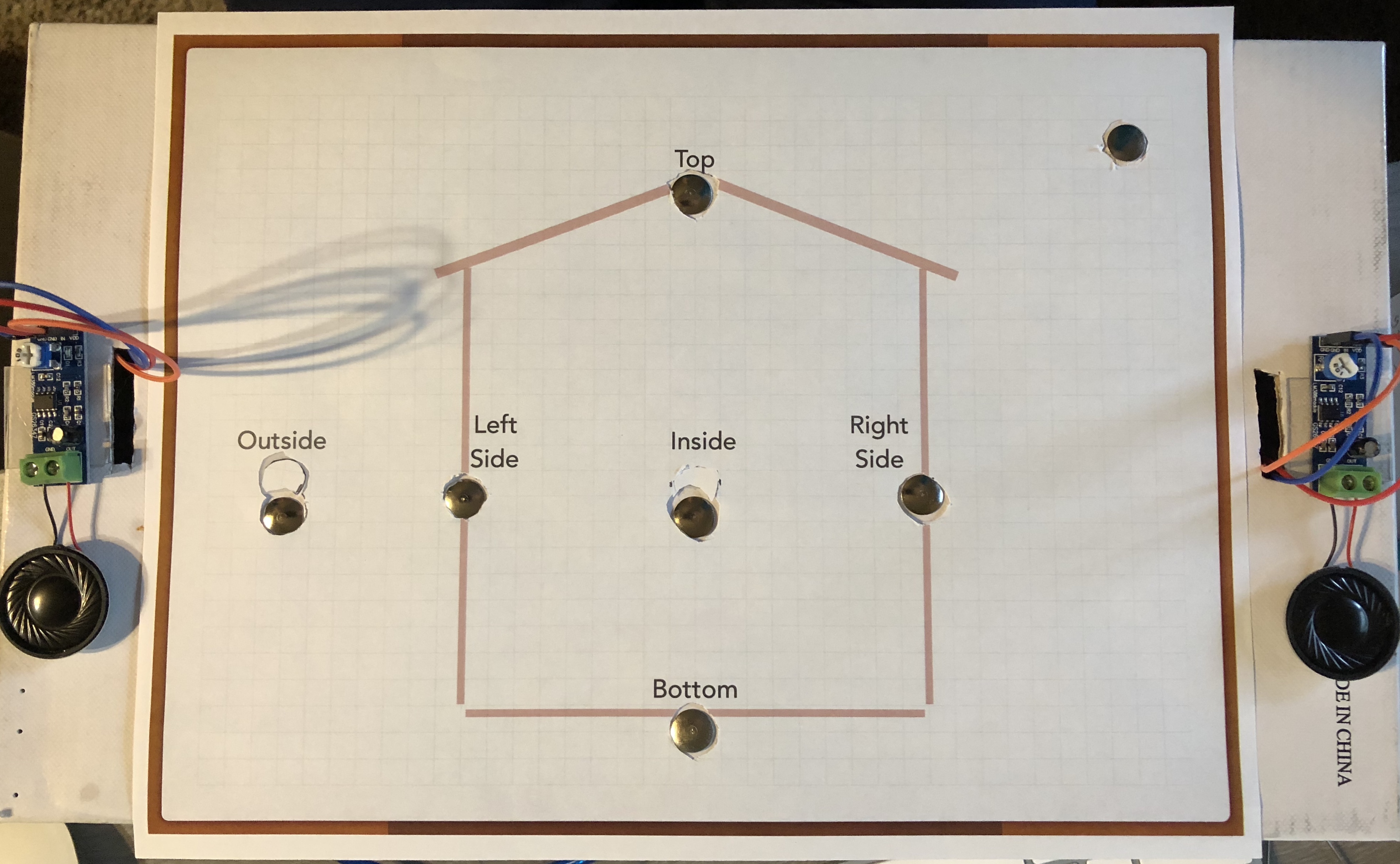
I have attached the printouts for the vocabulary lessons covered in the sketch. Feel free to print them out (in color if possible) or create your own. Cut out the circles on each page, then place the sheet on top of the box. Center the thumbtacks in each hole then, while holding the box open, attach the female ends of the wire to the appropriate thumbtack.
Modify the sketch for which function you wish to use, place the appropriate sheet on the box aligning to the thumbtacks, plug in the USB cable to the computer, upload the sketch onto your Arduino and enjoy!