Arduino Controlled Object Following Halloween Skull
by procrastination in Circuits > Arduino
948 Views, 6 Favorites, 0 Comments
Arduino Controlled Object Following Halloween Skull


This project takes a $5 skull from Target and makes it a much more interesting Halloween decoration!
Supplies
For this build, I mostly used parts that I already had on hand. The design could be simplified and consolidated if I had used different micro-controllers. Here is the list of items that went into the build.
Material Supplies:
- Plastic Skull
- Convex Lens
- Acrylic Base
- Wood Piece for mounting
- Glue gun
- Glue sticks
- Acrylic Paints and brushes
- Gauze bandage
- Drill and bits
- Box cutter
Motion Following Electronics:
- 1 Arduino Uno
- 2 Ultrasonic Sensors
- 1 HS-422 Servo
- 2 UV LED
- 2 30-100 Ohm resistors
- Many Jumper Wires
LCD Screen:
- Arm Mbed LPC1768
- µLCD-144-G2
- SD Card
Wire Up the Hardware


Using the circuit diagrams above, wire up the hardware as shown onto a breadboard. If you are going to mount this directly, make sure to use long wires to give yourself plenty of slack.
When the jumper on the back is removed, the ultrasonic sensor acts like an HC-SR04 with a trigger and echo pin. When the jumper is in place, you use 9600 baud UART to communicate with the sensor. We will be using it in the HC-SR04 mode.
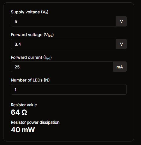
To calculate the resistor size, I used the values given from the product page and entered them into a LED calculator. It doesn't need to be exact though. Anything around the calculated size will work. It will just change the brightness and longevity of the LEDs.
You should power your circuit from an external power supply, as trying to use the Servo with the USB connection can damage your Arduino. I used a power adapter to power the Arduino UNO in addition to the USB port.
Prepare the SD Card


This LCD is a bit strange in the way that it stores data. You need to use their software, as specified on the datasheet because it requires an unformatted uSD card with the RAW image and video files. You can download their IDE here. Specifically, you need to use the Graphics Composer 3 software tool.
Find a GIF you want to play on the screen. I used the eye GIF that I have attached here. Next open up Graphics Composer 3 and perform the following steps:
- Click add to find the GIF on your computer.
- Change the screen size to 128x128
- Save to generate a file required by the program. It should look like this:
The sector and offset need to correspond to the values in main.cpp for:
- Finally, flash the data to your SD card.
When you start the mbed, it should play the file specified. For more details on the LCD, check out this wiki page.
Write the Software

The object following code comes from this instructable. The latest software that I used can be found here. The code for the LCD is only the main function. To get all of the libraries needed go to the GitHub page linked above.
Install the Arduino IDE and copy in the code for the motion following. Connect the Arduino UNO to your computer via USB and flash the software.
Depending on your setup, you will want to modify the variable for the max distance it detects in motionfollow.ino
I used 50 inches and it worked well for me.
For the MBED micro-controller, I used keil's online editor and compiler. Download the project, import it into keil and upload it to the MBED.
If your flashed the SD card correctly, you should see your image playing and the skull should be following you.
Prepare the Skull

.jpg)
Cut out a large circle in the back of the skull to give access to the head cavity where you can mount the electronics.
Using your box cutter, cut a circular hole in the forehead of the skull to fit the Convex Lens, with enough room to mount the LCD screen behind it vertically or horizontally. Hot glue the lens onto the hole as well as the LCD behind it.
Cut two small slots in the eye cavity to route the wires from the ultrasonic sensors to the inside of the skull. Hot glue the ultrasonic sensors to the face and where the wires go into the eyes.
Drill two small holes to mount the UV LEDs under the eye cavity. I didn't make them to fit the LED, but just made it so they could shine up through it. I routed and attached them to the inside of the skull.
Drill two small holes through the bottom of the skull in the mouth area. Attach the servo to the skull with a zip tie routed through these holes and around the servo.
Finally, attach the servo to the acrylic base and the base to the piece of wood to give it extra stability.
I placed all of the electronics on breadboards to test, hot glued all of the connections to keep them stable and then mounted everything in the skull cavity. It became quite the ordeal. If I was doing this over again, I would probably make a PCB or leave the electronics out of the skull.
Finish the Skull (Optional)


At this point, you should have a working object following skull. To hide the ultrasonic sensors, attach the gauze bandage around the eyes. Some gauze materials will impact the Ultrasonic sensors, so it will require some experimentation. The paint can't be too thick, as it will also interfere with the sensors. You can go back and poke holes in the paint if it is an issue.
Paint blood coming from the eyes and forehead. To make it even more lifelike, paint the skull to give it depth and texture.