Arduino Color LCD Message Clock
by johnag in Circuits > Arduino
6036 Views, 62 Favorites, 0 Comments
Arduino Color LCD Message Clock
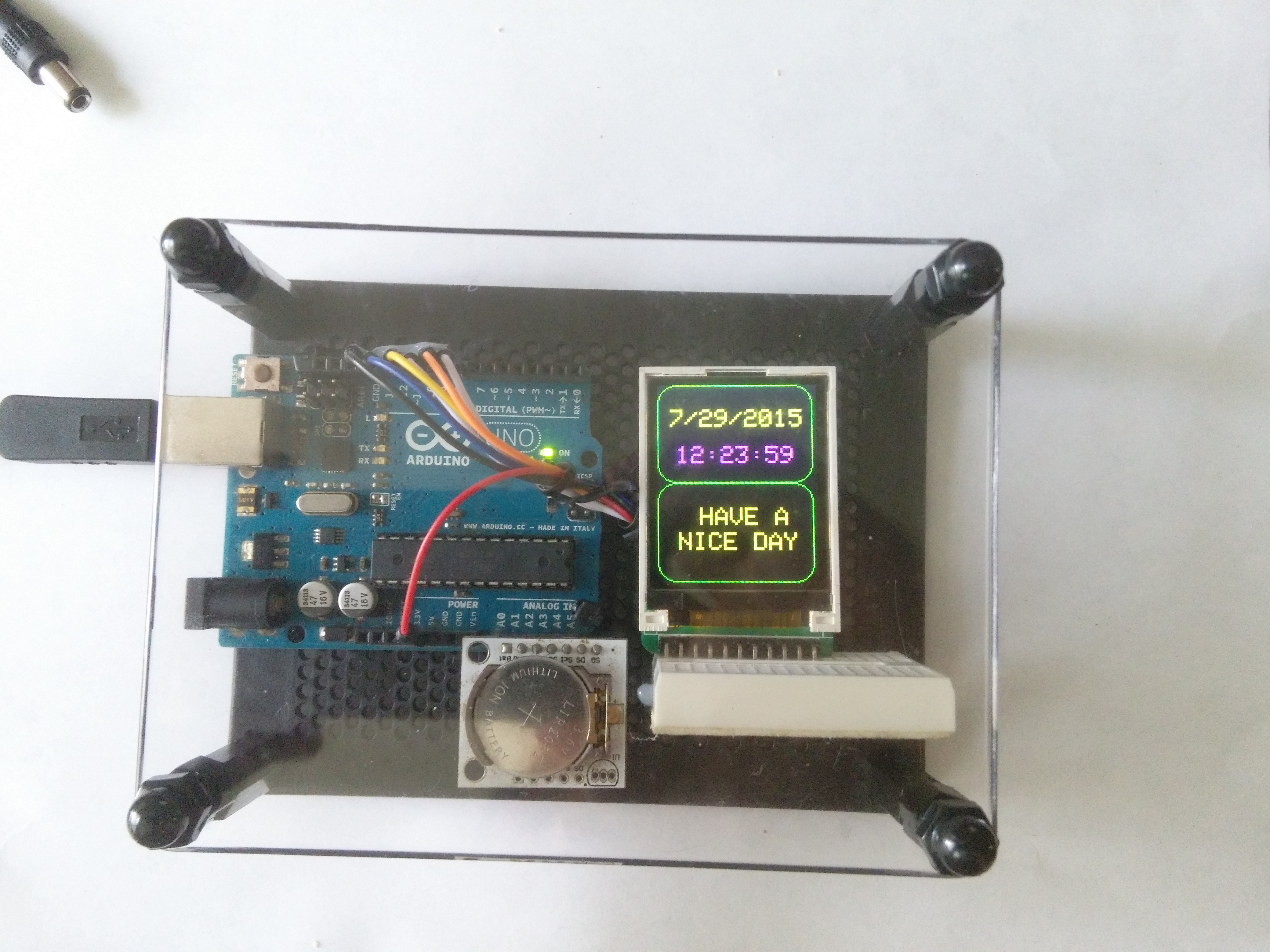
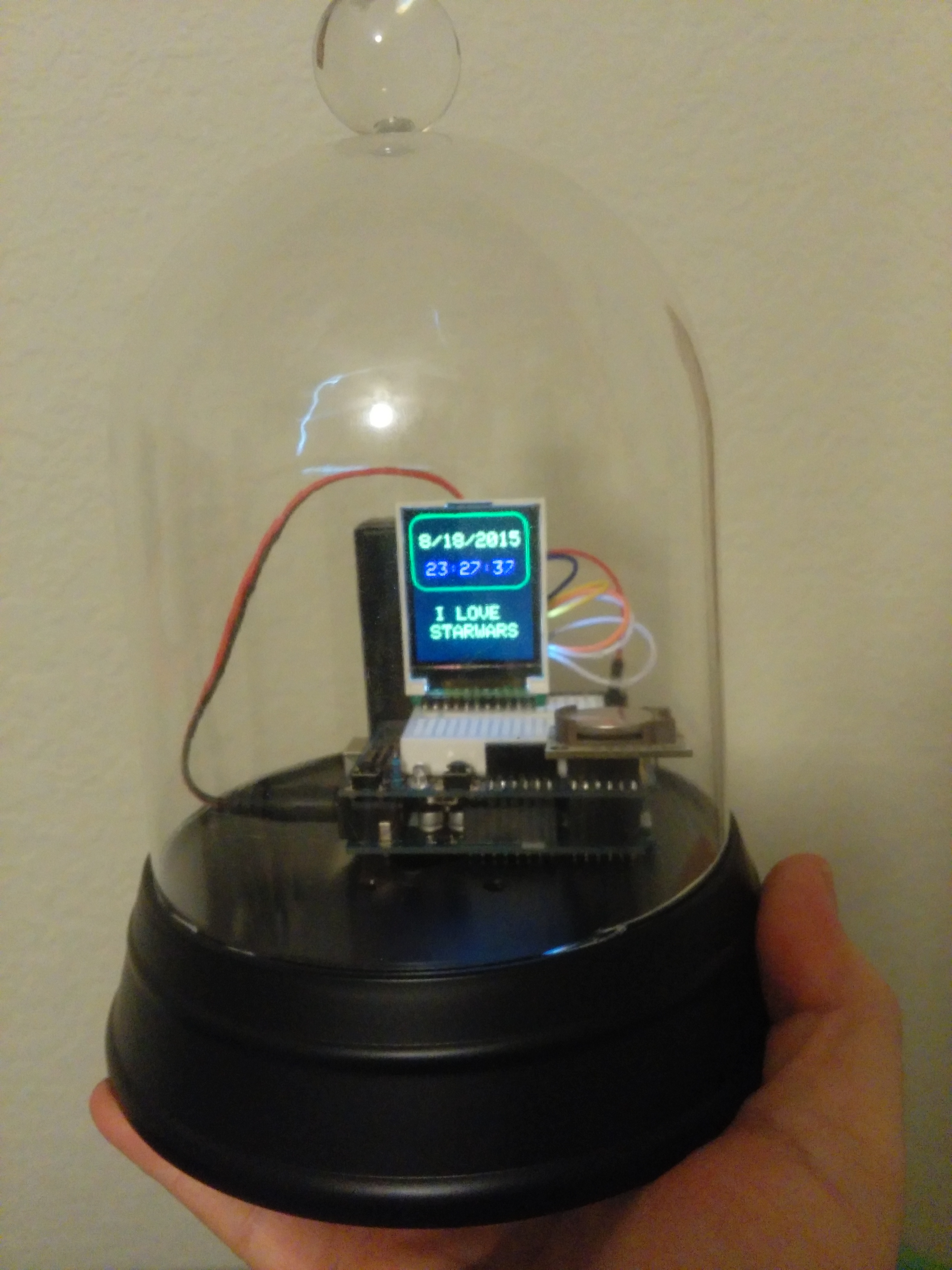

This instructable will show you how to build a Message clock that can be programmed to show messages at specific days and times.It also has an RGB LED and a Speaker to play tones and light up to make the Message more entertaining.
If you decide to build this instructable, not only will you end up with a cool message clock, but you will learn how to use the 1.8" color display, how to play musical tones, how to drive a RGB LED, and have a great platform to display your Arduino projects.
I haven't made an instructable in over a year and since then, the instructable editing UII has changed quite a bit. Still trying to get used to it. For those who have seen or built some of my other Arduino instructables, I'm using basically the same hardware components that I used in making the Enviroment Monitor, however, the wiring and component layouts are different.
The construction is fairly simple and I've kept wiring to a minimum by using the Arduino pins to provide power and ground to the RTC Clock and the RGB LED. So lets get started...
Parts List
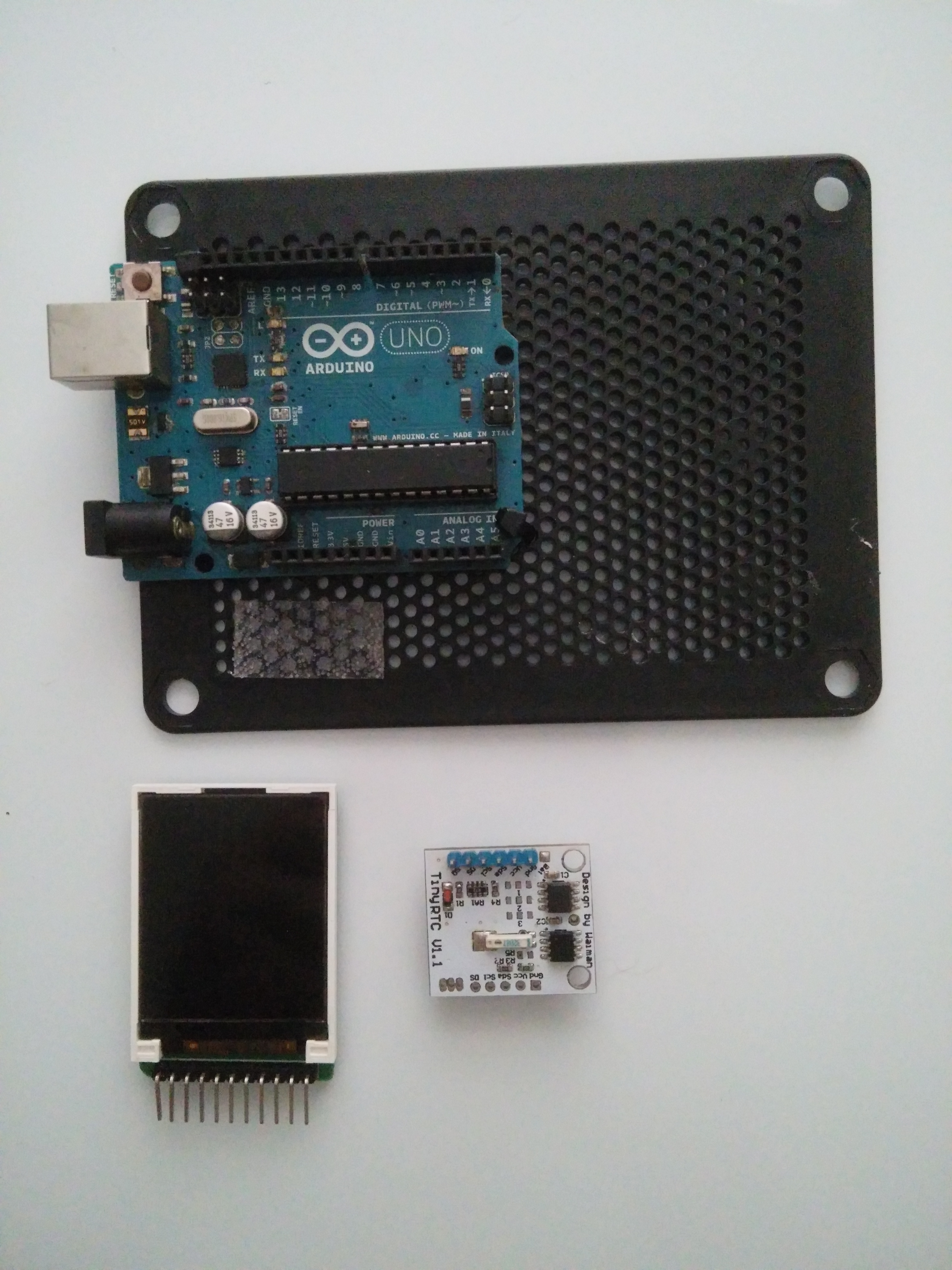
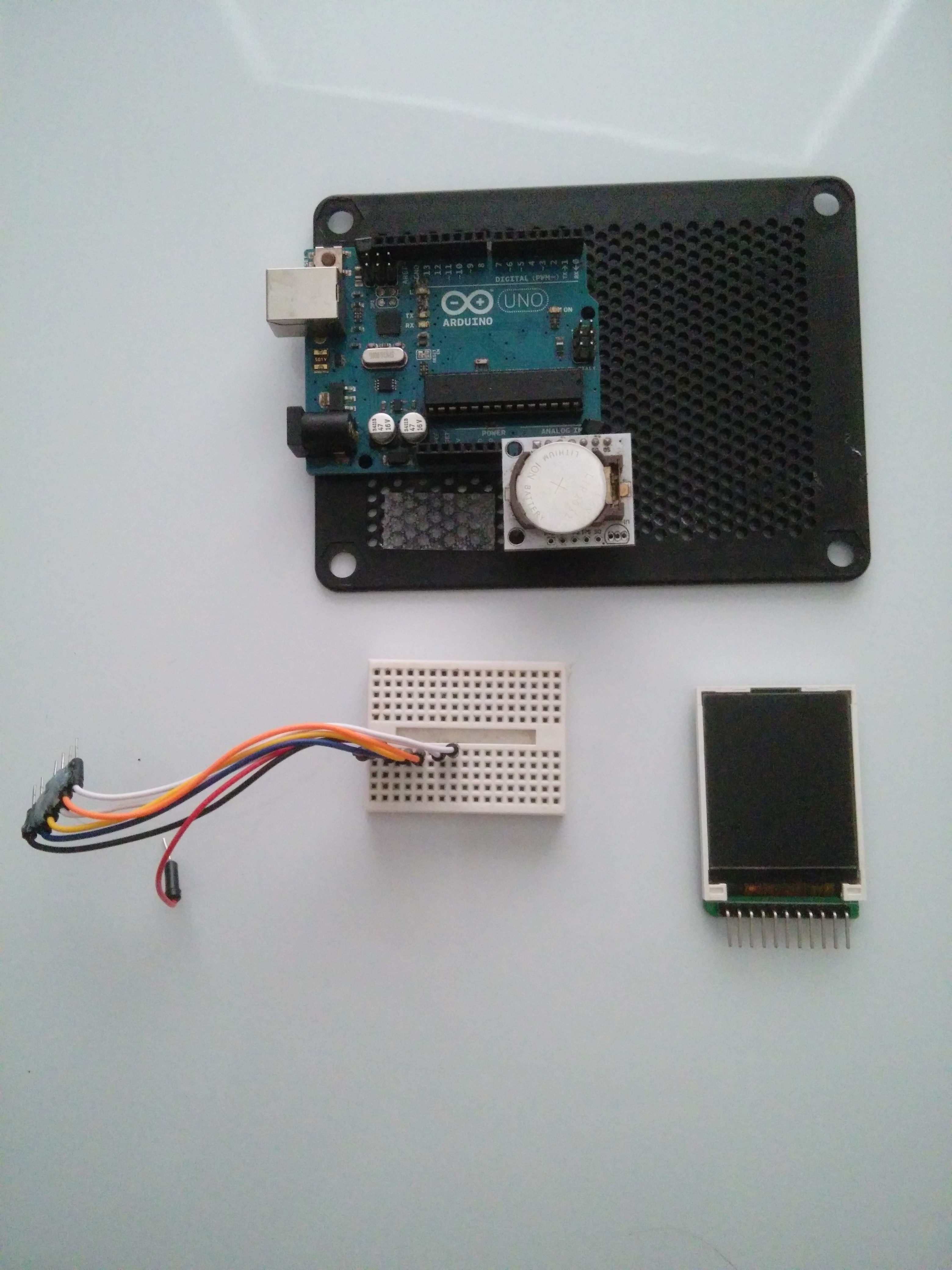
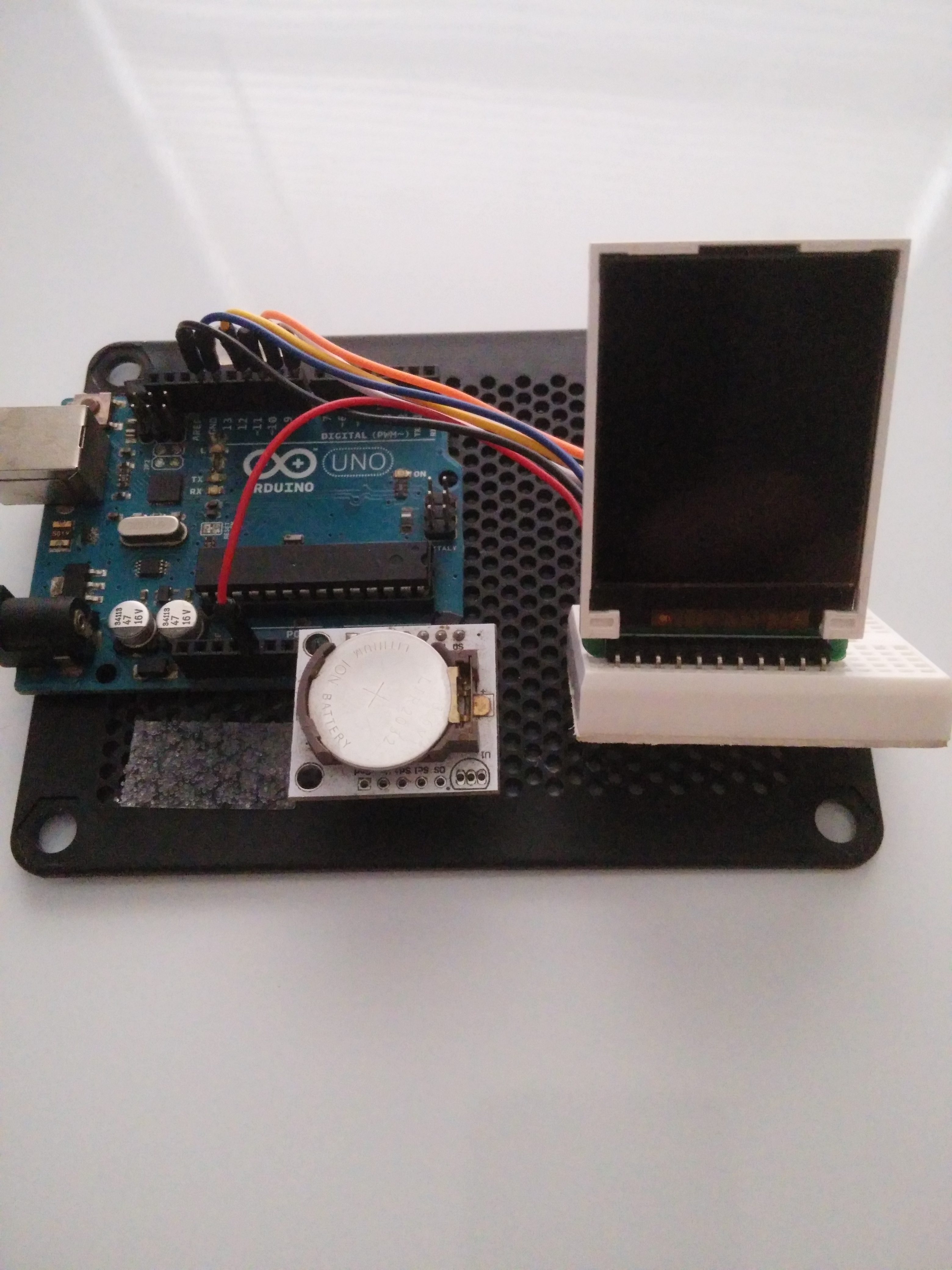

Before you get started on the build, you will need the following parts:
Obviously, you will need a Computer with the Arduino IDE installed and a USB Cable to connect your Arduino to your PC..
I Have inserted hyperlinks to all the components list from Amazon.com but you can shop around other places to get the parts.
Note: the links to the parts are not necessarily the same parts I used, because I used the parts I had available on hand and purchased a while back..
Sainsmart "1.8" TFT Color LCD Display
A TinyRTC Module you will also need 2.54 single row pins to solder on to the RTC module, because most RTC modules do not come with pins soldered to the PCB.
An RGB LED Module (OPTIONAL , IF YOU WANT A LIGHT SHOW)
A speaker or piezo buzzer (OPTIONAL , IF YOU WANT SOUND)
Mini Breadboard (with prototype shield, protoshield is optional but recommended)
You will also need to install these libraries into the Arduino IDE:
The Wire Library
The SPI Library
The RTC Library
Adafruit ST7735 library
Adafruit GFX Library
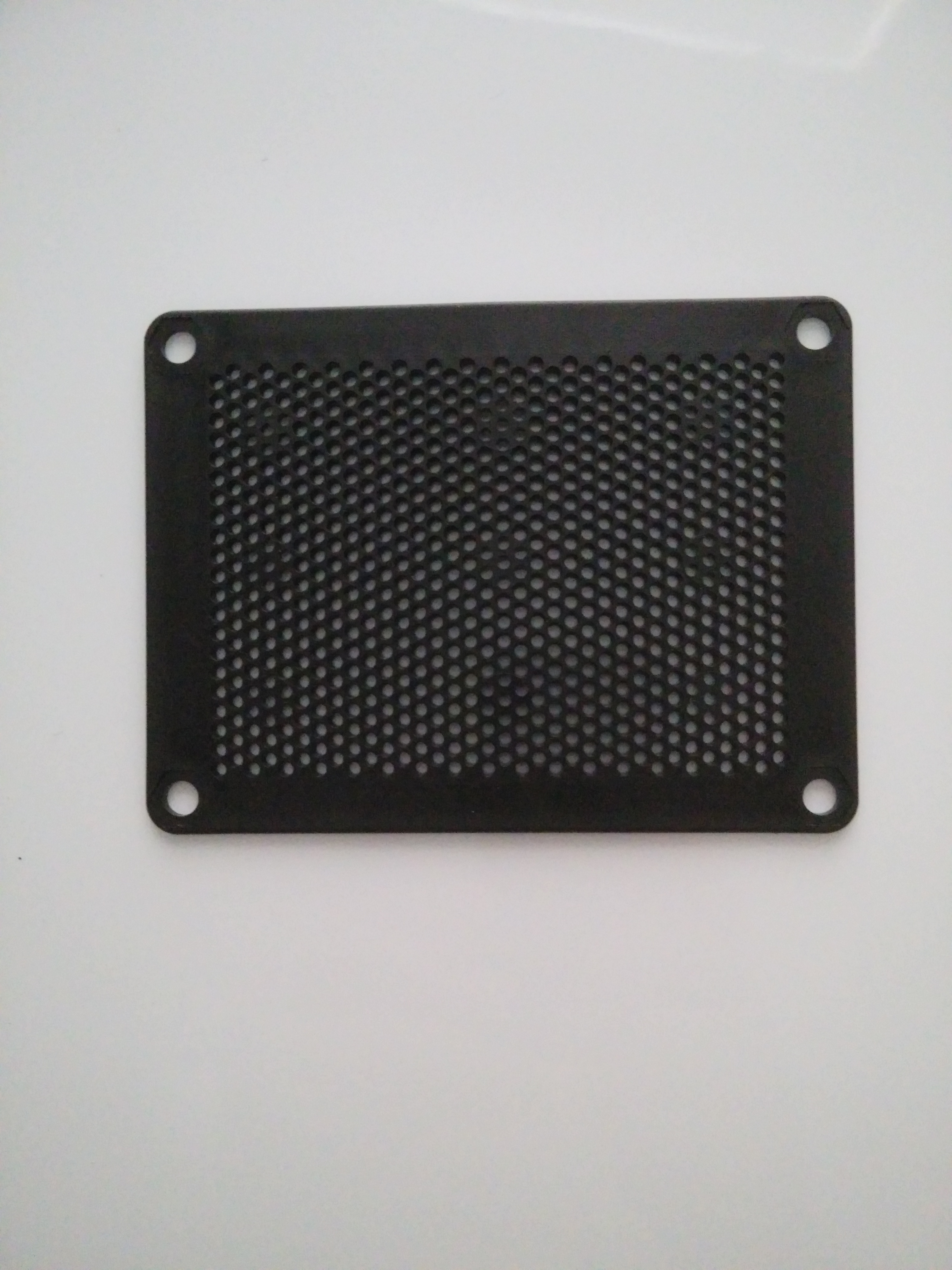
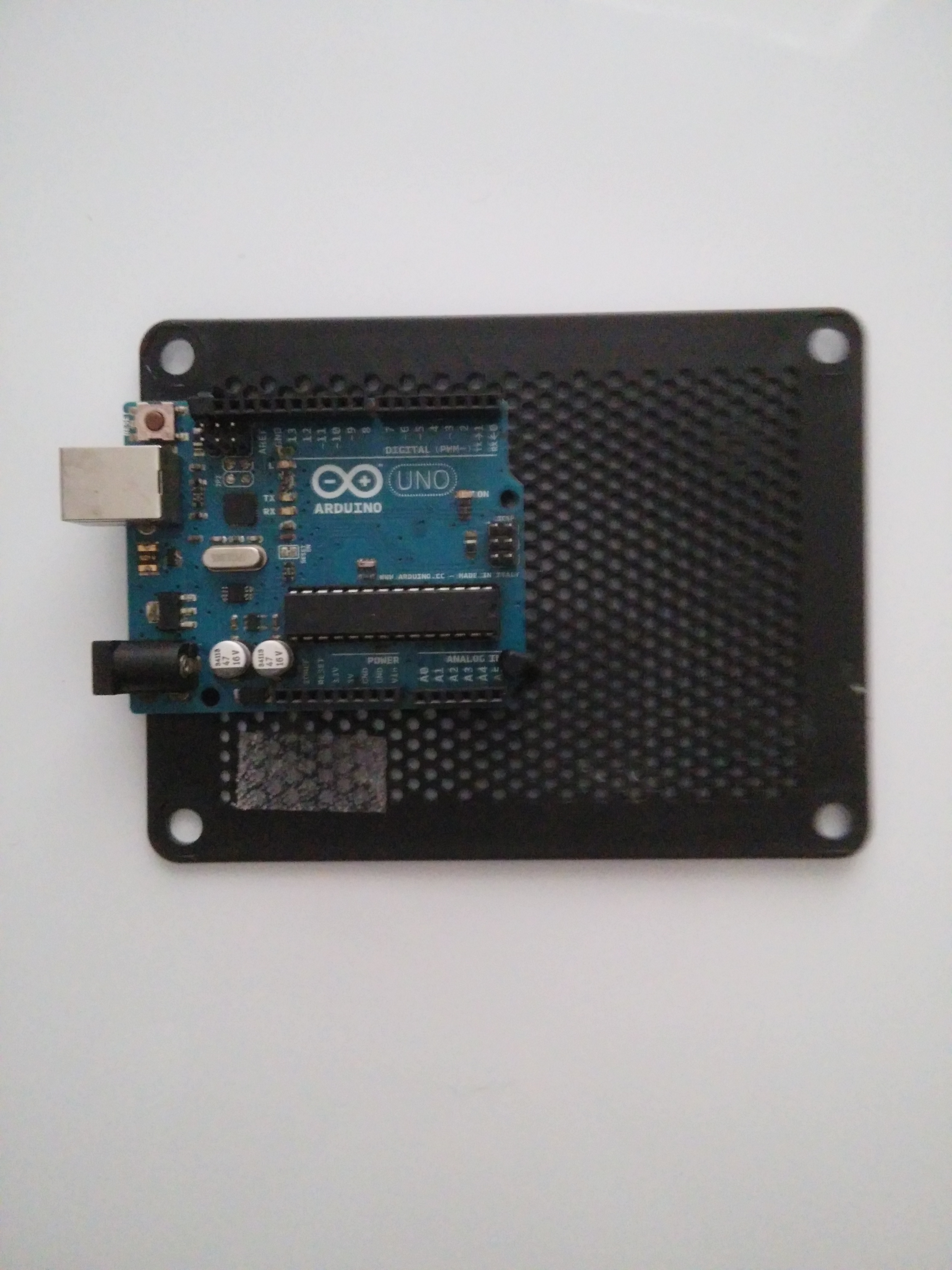
If you like the acrylic enclosure, you'll need a plastic pin art pin impression toy and two small zip ties
Tools
You may need the following tools:
Soldering Iron, if you need to solder the inline pins to the RTC module.
Glue Gun, if you want to glue the breadboard to the acrylic pin art case, and if you want to glue the jumper wires together.
Build Overview
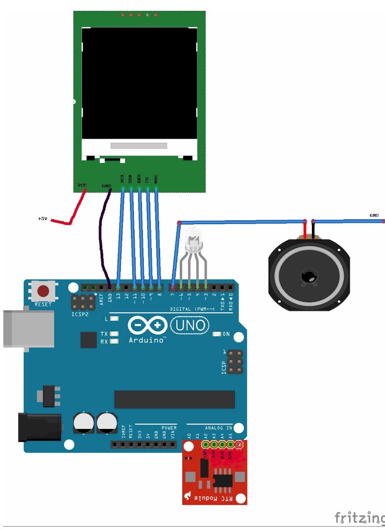
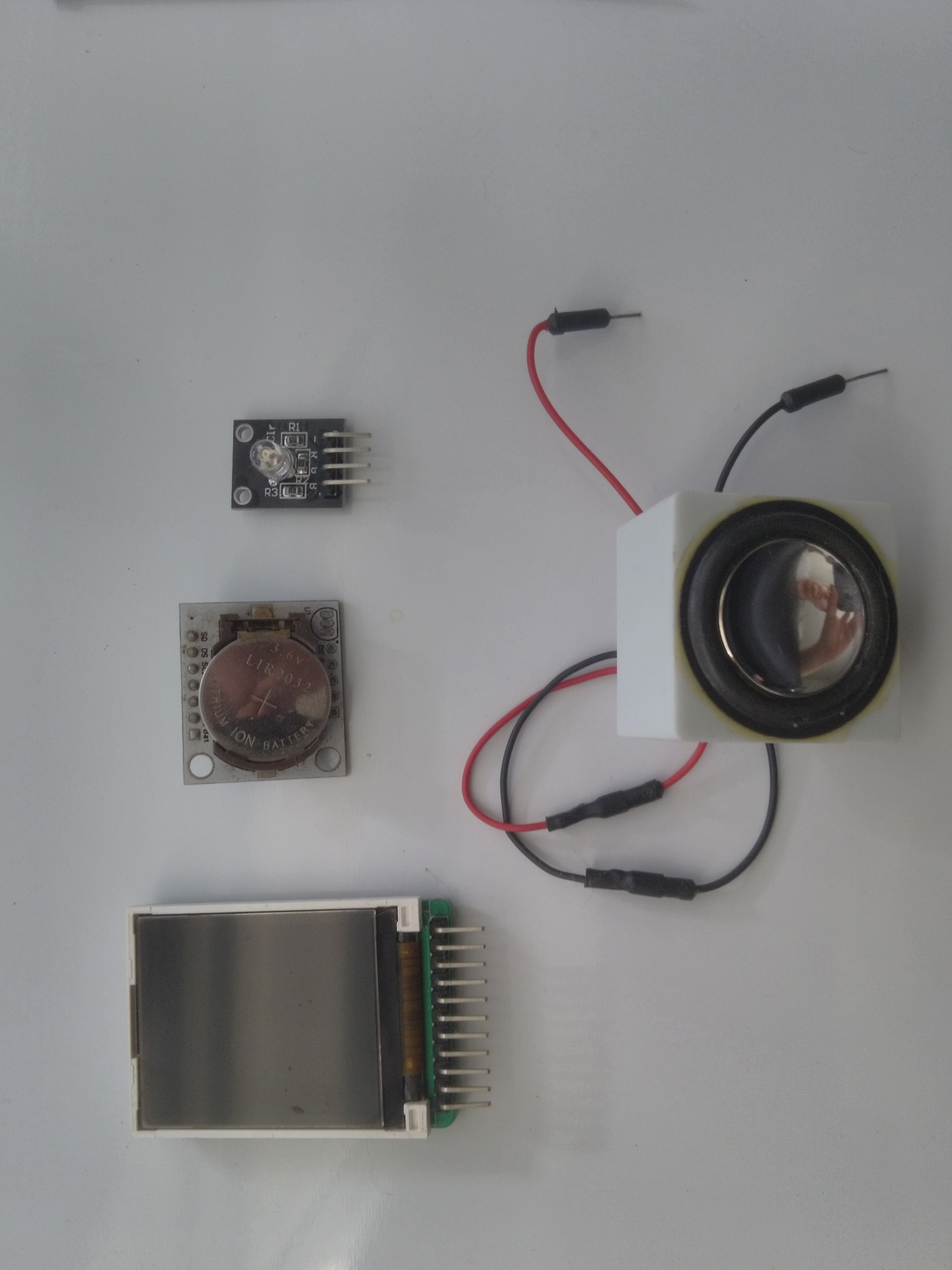
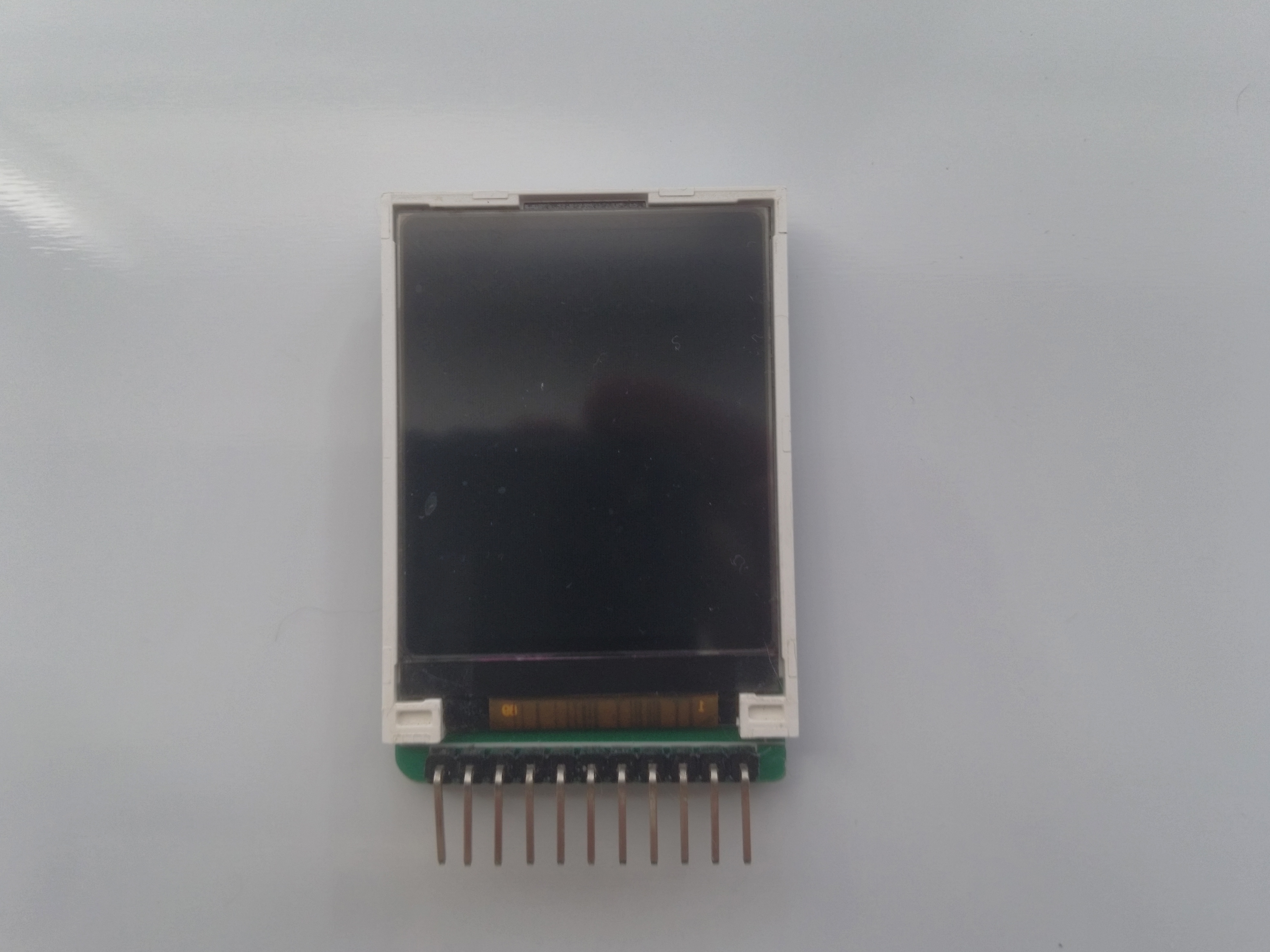
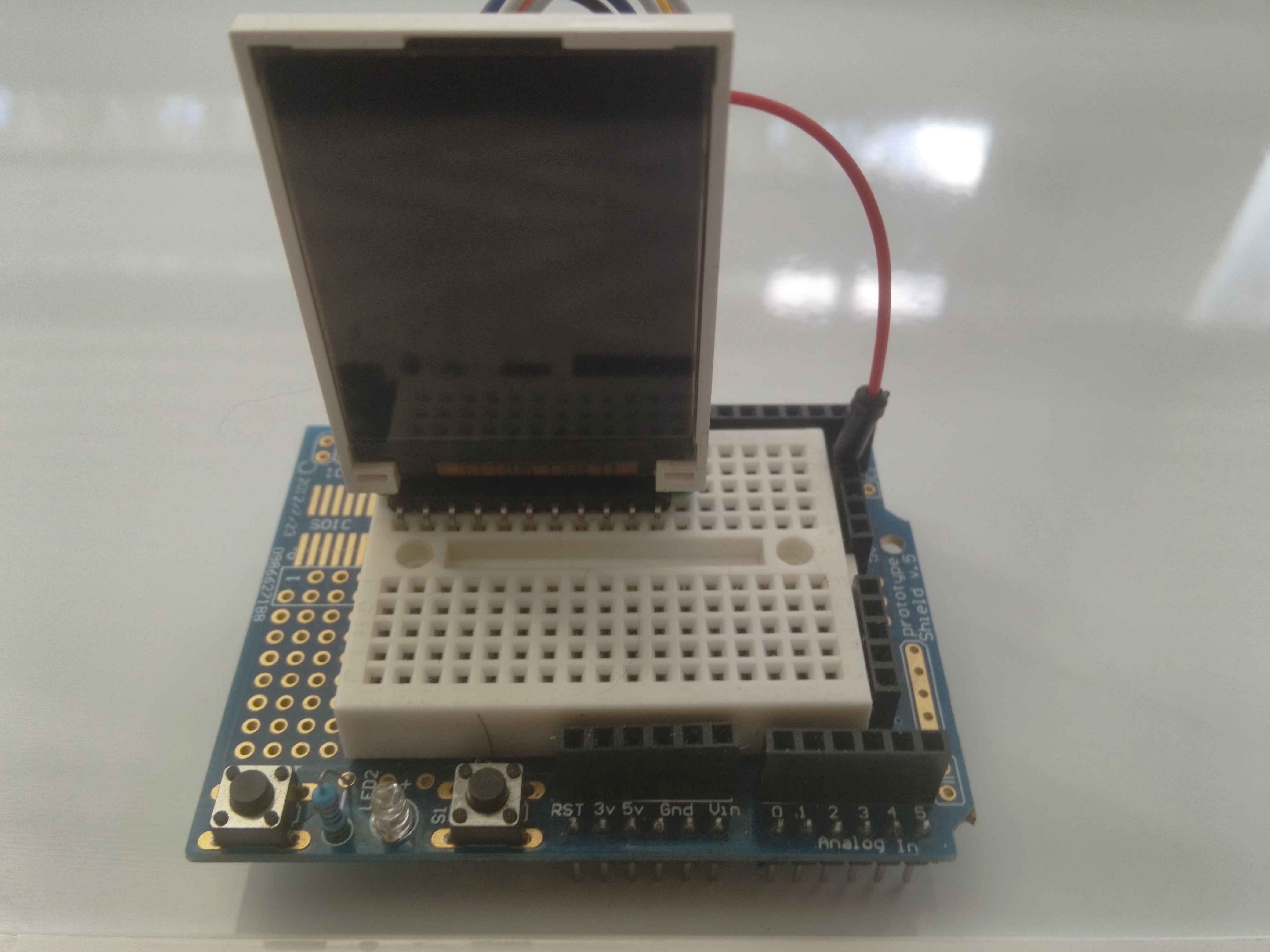
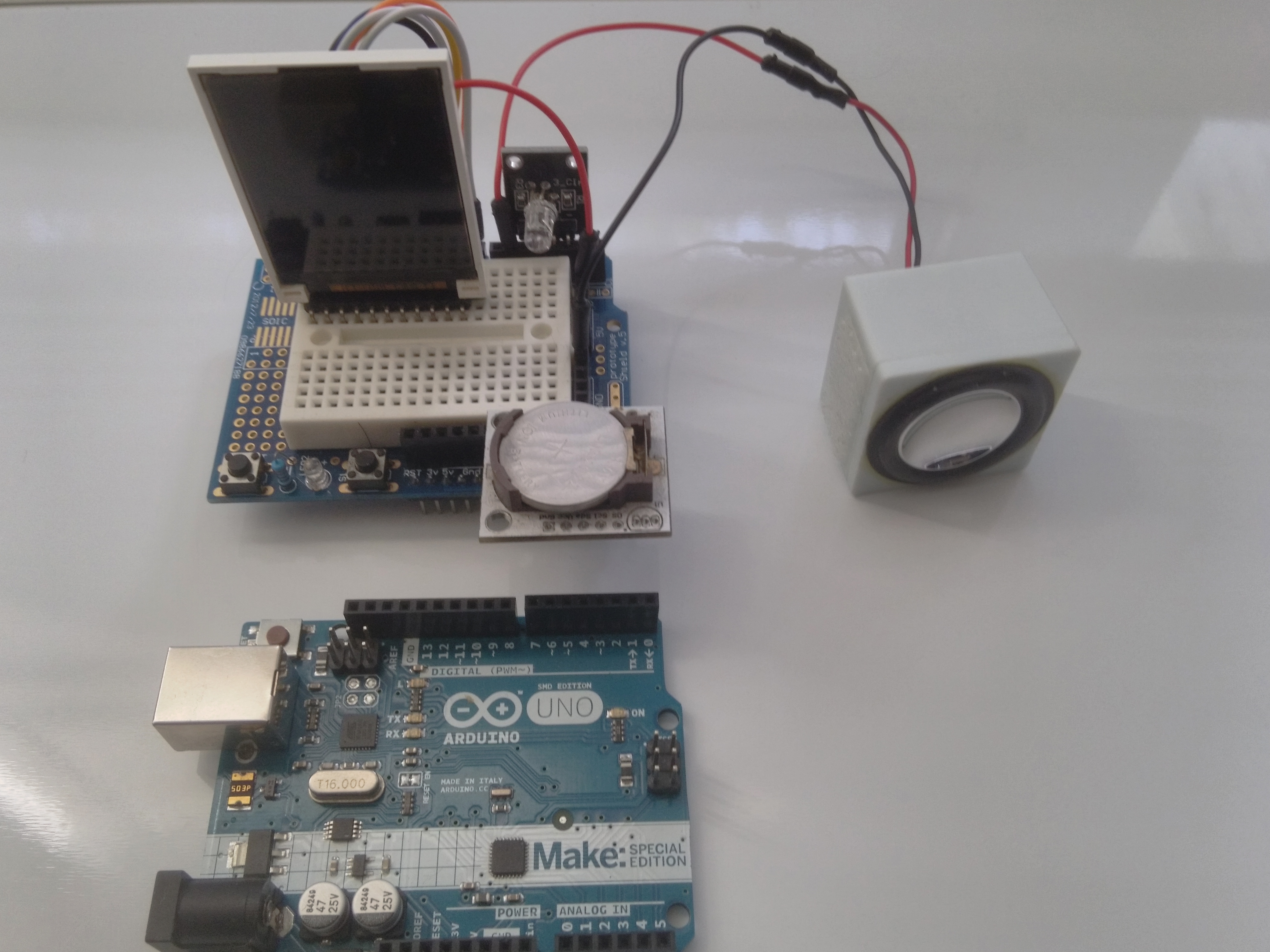
There are several ways to put this project together; One way is using the prototype shield with the mini breadboard, another is using the mini breadboard without the shield,. or you can use female to male jumper wires to connect the display to the Arduino. Regardless of which way you choose, the wire mapping is the same.
Refer to the Pictures to guide you through the wiring.
We will be setting up and testing each of the components individually to make sure they are installed and working properly before we connect the next component.
first We will setup sound and light, then the RTC clock and the display, and end with the enclosure and power options.
As we set up the hardware, We will load some sketches to test the components individually before we load the final message clock code. This will make it easier to understand what the final clock sketch is doing.
One last note before we start. The musical tones are not written by me. I borrowed them from different websites on the internet I googled a while back, and as much as I would like to give credit where credit is due, I didn't keep that information while I was playing around with sounds on the Arduino and I removed all comments to try to make it easier understand the code.
Sound and Light
Sound
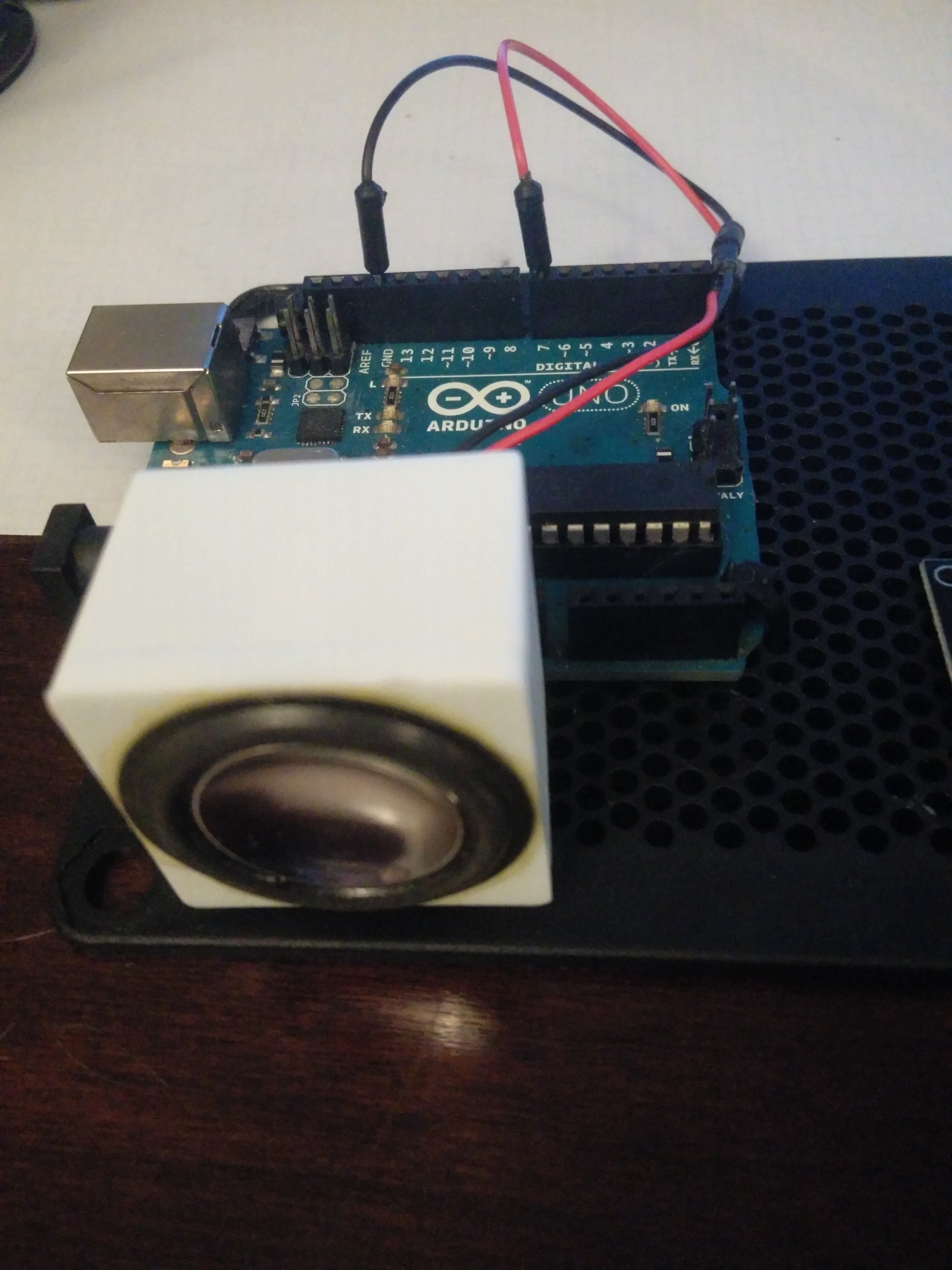
Let's start by plugging in a speaker ( or buzzer) and make some sounds. We are going to use Digital pin 7 as the sound output to drive the speaker. The speaker I'm using came from a littleBits Synth speaker module I got it at radioshack on clearance for about $1.50, not only does it look good, but it sounds good too. Unfortunately the price on Amazon is like $40, so I'm not recommending you buy it. You can use any Arduino compatible speaker or buzzer, but sound output quality varies with the quality of the part you choose.
I removed the plug from the end of the speaker wires and used a red and black jumper wire, cut in half, to make the pins compatible with the Arduino. All you need to do is strip about a 1/2 inch from the cut end of the jumper wires, and do the same to the speaker wires. Tie the end of the wires together (red with red and black with black) and use heat shrink tubing or electrical tape to insulate the connection. If you have a soldering iron, solder the wires together for a more secure connection, before you apply the insulation,
Plug the red wire to digital pin 7 and the black wire to the Arduino GND, as shown in the picture.
You are now ready to load a sketch and play some tones.
You should have the Arduino IDE installed on your PC, and your Arduino plugged into a USB port on your PC.
Open the Arduino IDE and copy the code in the melodytone.ino file attached to this step into the Arduino IDE sketch editor. Compile and run the code
You should hear a melody playing, if not check the wiring, and make sure you have the proper USB Driver installed for your version of OS software.
Light and Sound
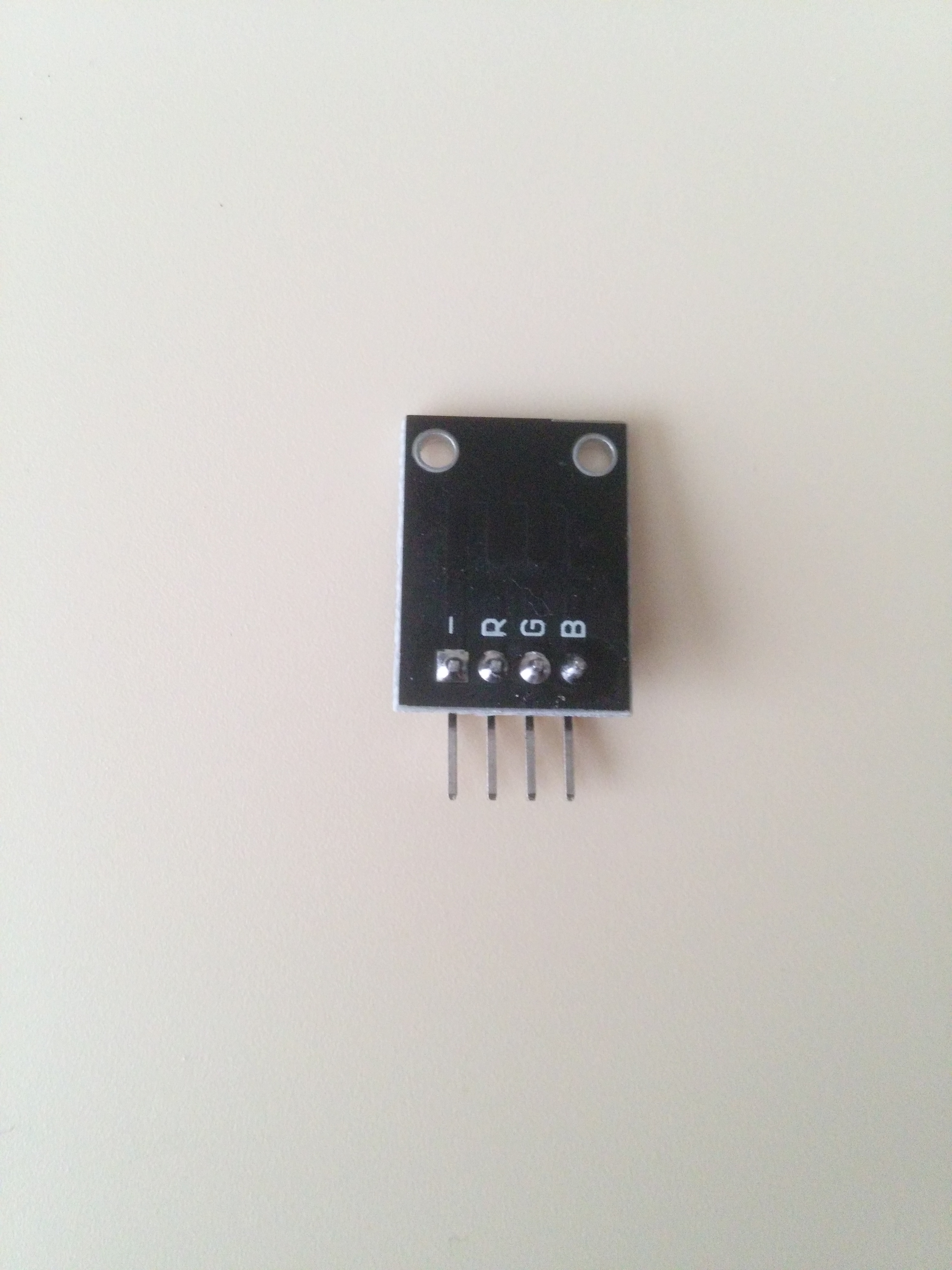
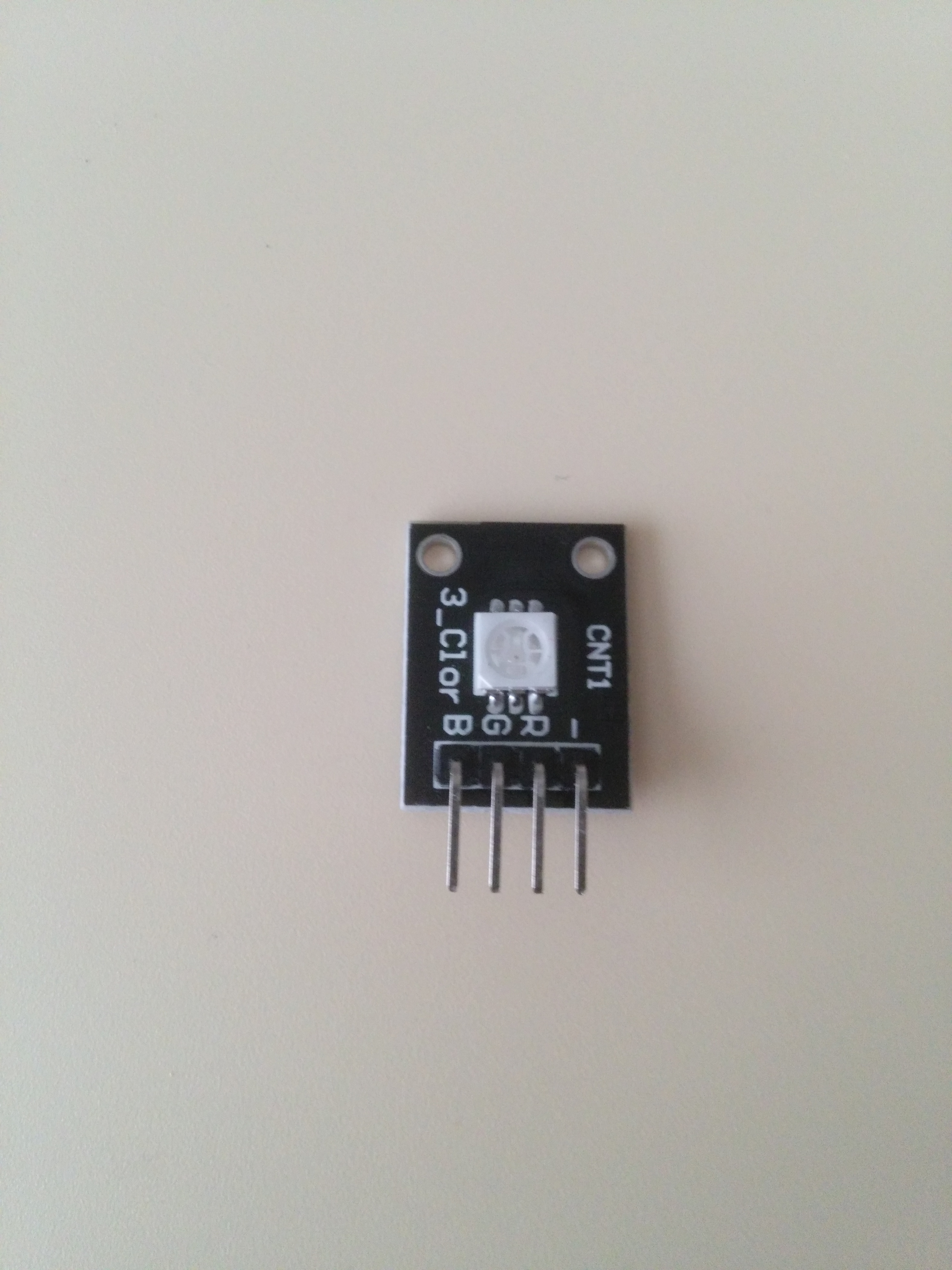
Now, Plug in the RGB LED module from Digital pin 3 to digital pin 6. pin 3 is used as the GND for the RGB LED.
once that is done, copy the code in the happybirthdaytone.ino file attached to this step into a new window in the Arduino IDE
Compile and run the code. You should hear the Happy Birthday song and the LEDs should be flashing, with random colors, in sync with the music.
Hopefully you got the sound and light to work and you're ready to setup the RTC clock module
RTC Clock
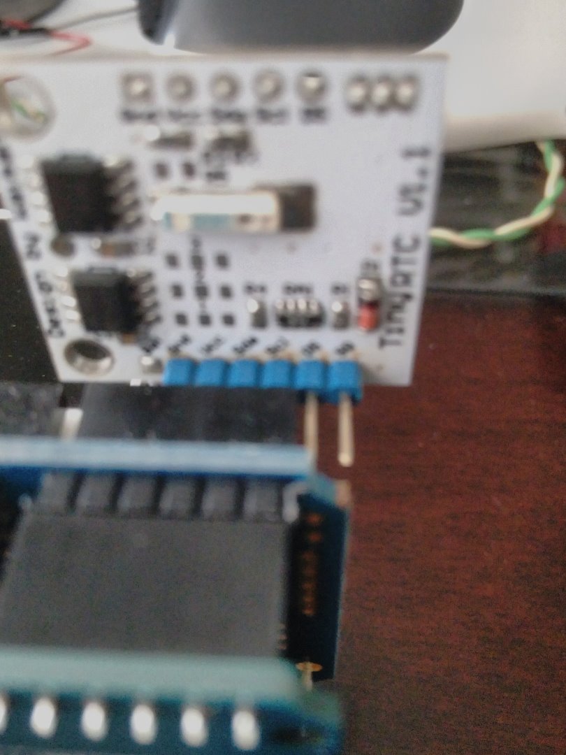
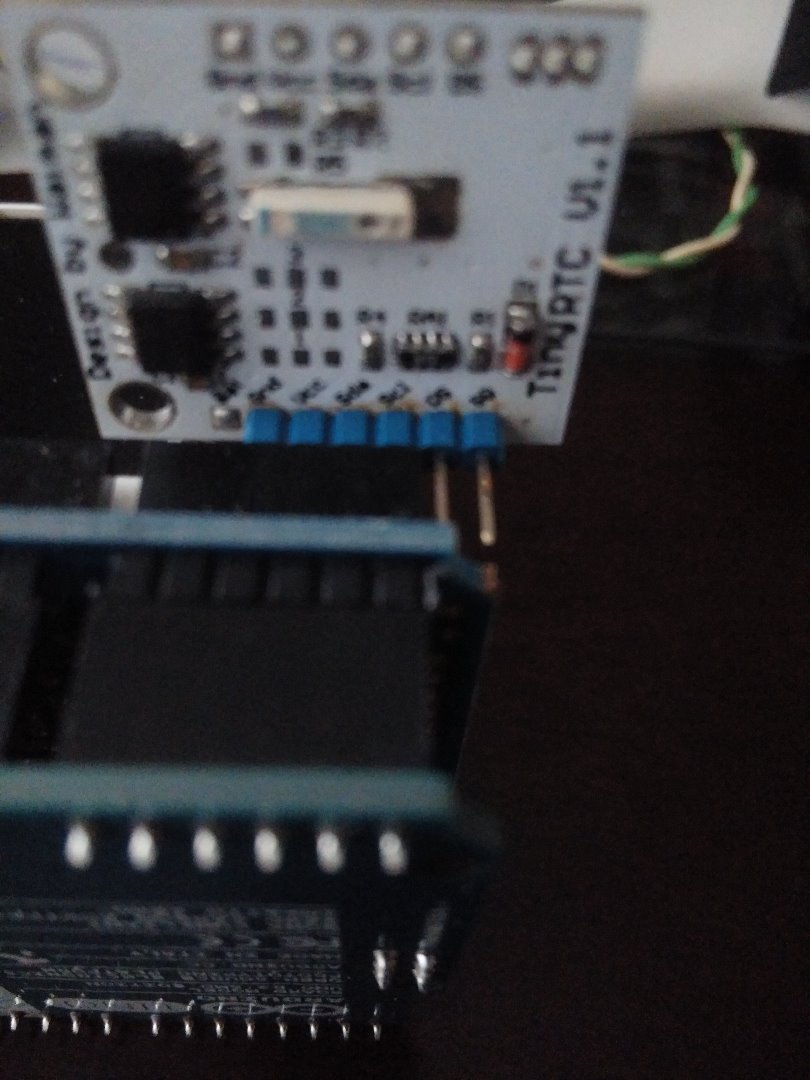
To set up the RTC , you first need to solder the in line pins to the RTC module. Once you have the pins soldered, You will plug the pins into the Arduino analog pins A2 to A5
Pin A2 Plugged into RTC GND
Pin A3 Plugged into RTC VCC
Pin A4 Plugged into RTC SDA
Pin A5 Plugged into RTC SCL
The rest of the pins n the RTC are not used.
Note: if your RTC module has a different pin configuration, you might have to plug the RTC to the breadboard and use jumper wires to connect to the appropriate pins.
Once the hardware is set up, you now need to install the necessary libraries into the Arduino IDE to operate the RTC Module. The RTC module requires 2 libraries; The RTClib and the Wire library.
The wire library is pre installed in current versions of the Arduino IDE, so you only need to install the RTC library That I included in this step as a . ZIP File. Click on the file icon and download it to your PC. Open the file and copy the library to your Arduino libraries folder.
If you have the Arduino IDE open, you will need to close it. If the libraries Installed correctly you will see the RTClib option under the file -> examples menu.
NOTE:
If you want to test the RTC clock with the example sketches included in the library, and you have the RTC plugged in directly to the analog pins, you must insert the code below ( in the setup portion of the sketch ) in order to provide power to the RTC VCC and GND pins:
pinMode (A3, OUTPUT); // Plug the clock board into pins A2 through A5
digitalWrite (A3, HIGH); // Using pin A3 as a supply voltage to the clock board (VCC)
pinMode (A2, OUTPUT); // Using pin A2 as ground for the RTC (GND)
digitalWrite (A2, LOW); // Set this pin low so that it acts as Ground for the clock
Downloads
Connect the LCD Display
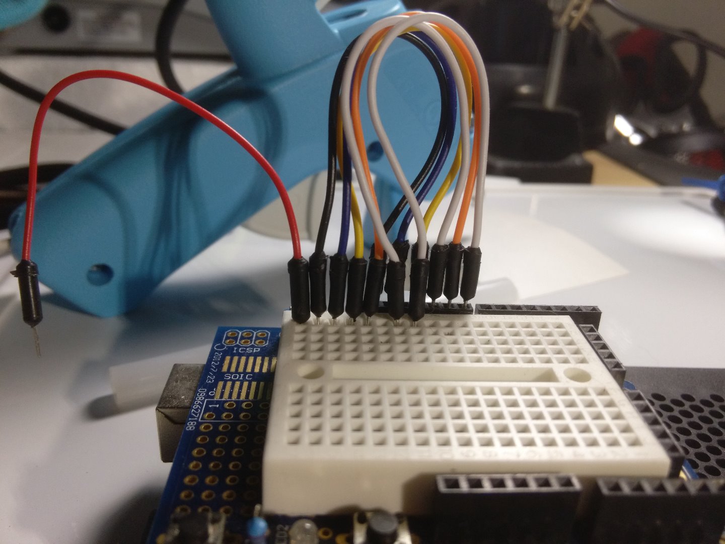
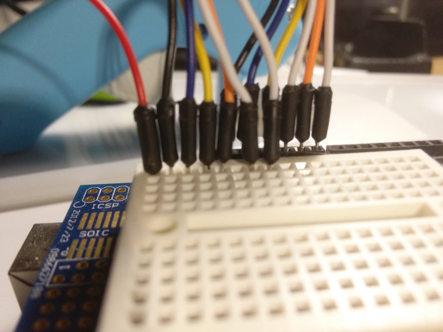
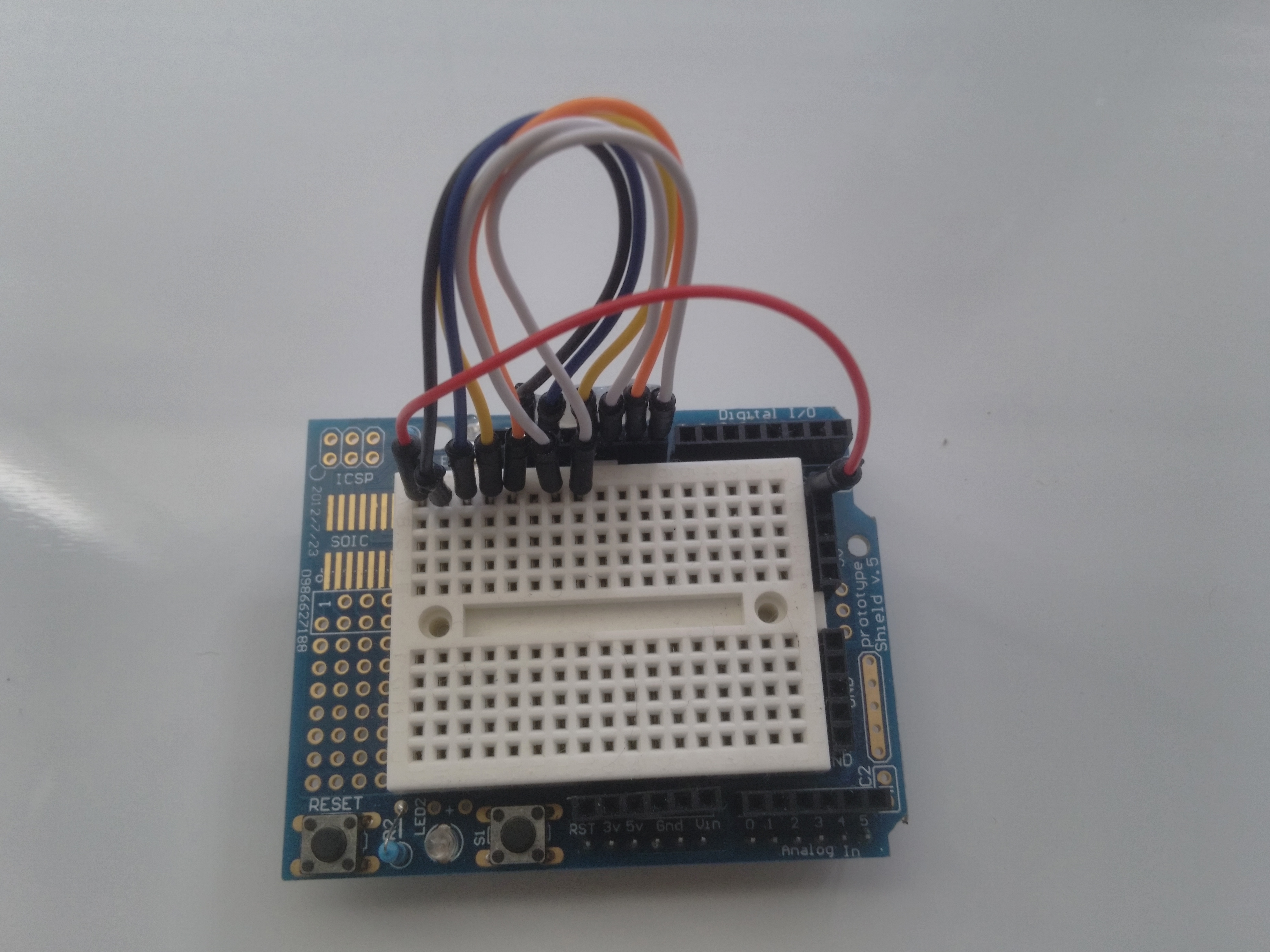
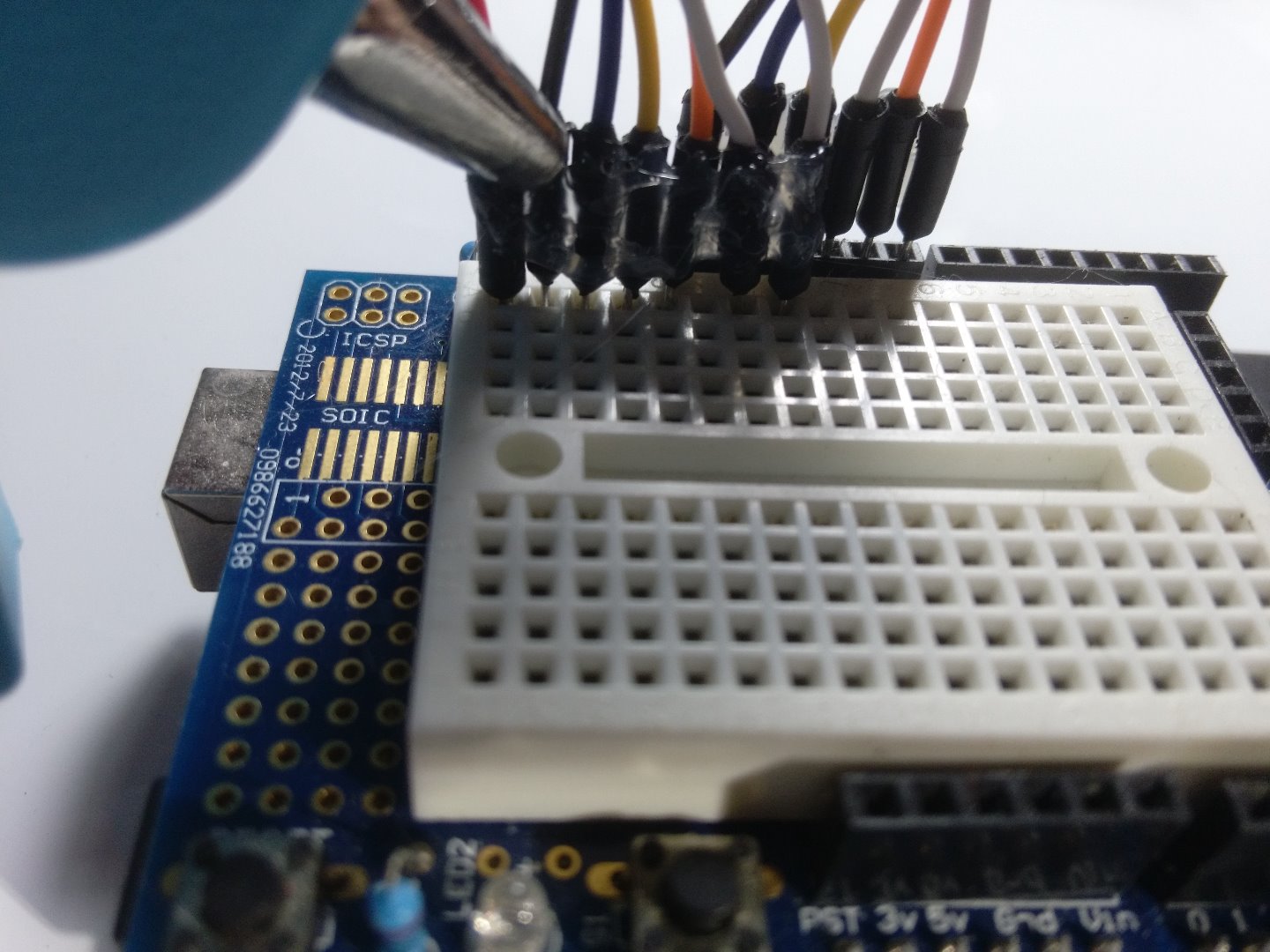
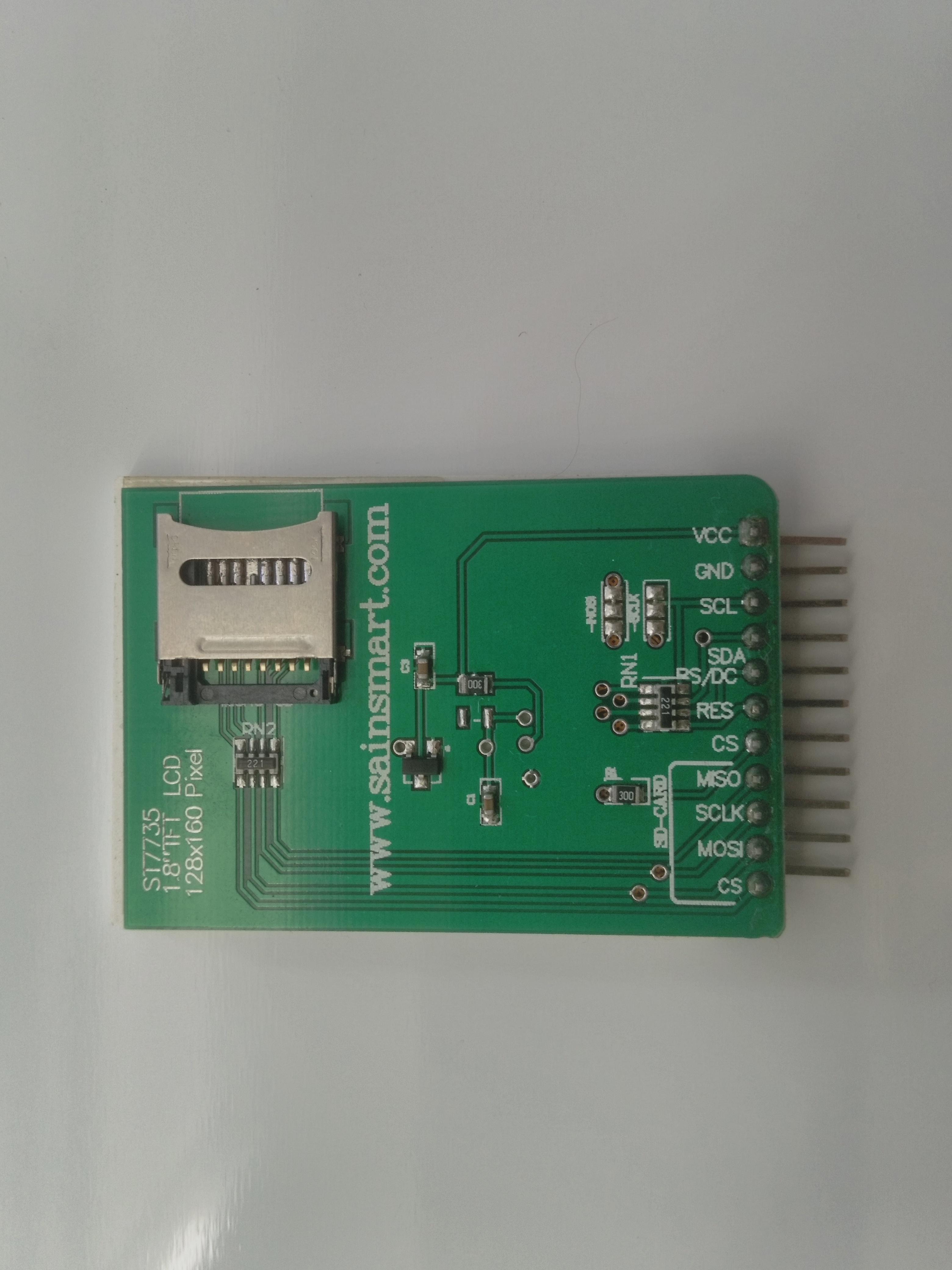
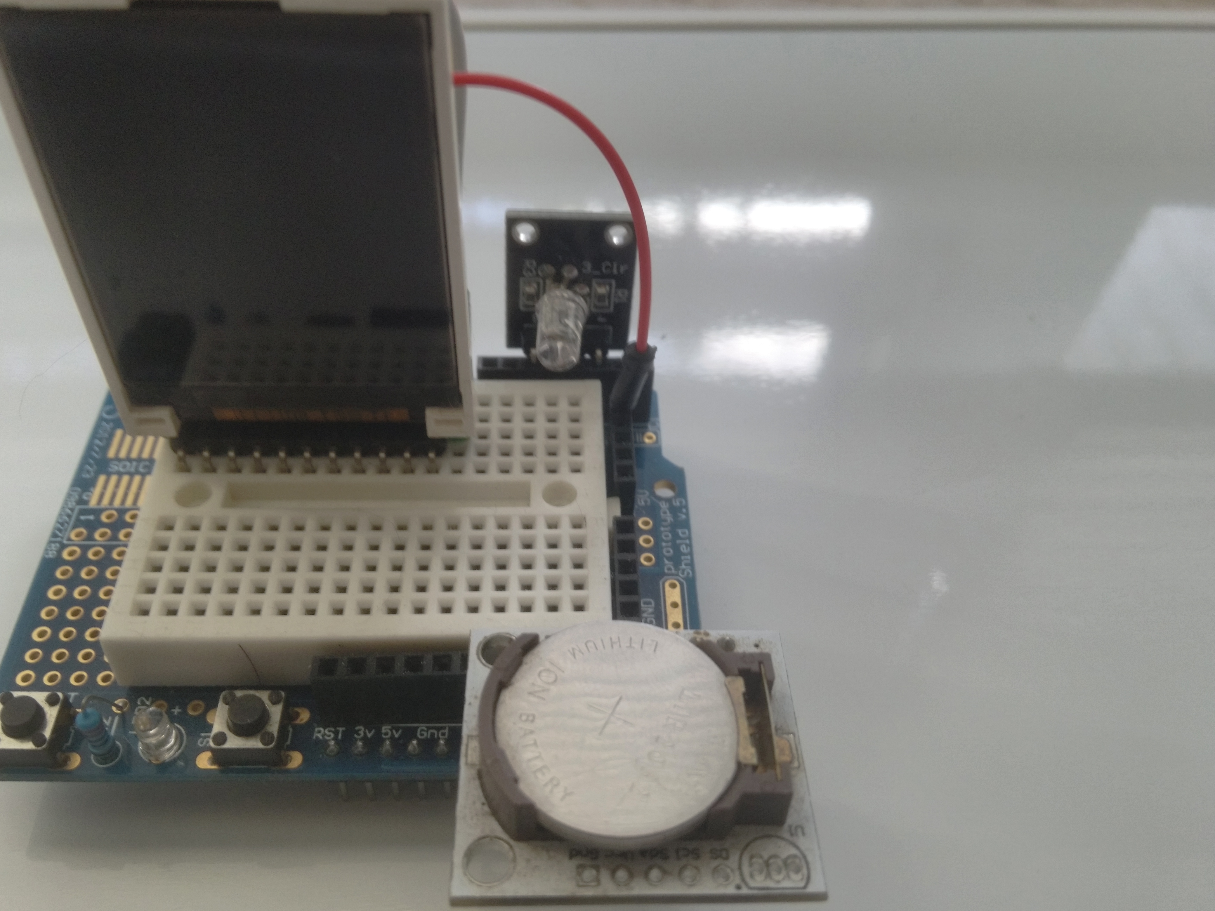
We will need 7 jumper wires to connect the LCD Display to the Arduino.
I used a hot glue gun to glue the pins in the wires together. This made it easier to connect and disconnect the wires and avoided loose wires from disconnecting. refer to the pictures if you want to do the same.
The wiring from the LCD Display pins to the Arduino is as follows :
VCC-------> Arduino + 5V
GND------> Arduino GND
SCL-------> Arduino 13
MISO-----> Arduino 11
CS--------> Arduino 10
RS / DC--> Arduino 9
RES-------> Arduino 8
We are using the wiring for the High Speed SPI interface , which is different from the wiring I used in my other projects, so if you built any of my other projects and are planning to use the same parts, make sure you rewire the display.
If you finished wiring the display, you need to install the required Libraries in order to test it out.
The Adafruit_GFX.h, and the Adafruit_ST7735.h.
I have included the Two Required Libraries in the Adafruit_LIBS.zip file. You will need to unzip the two folders and copy them to the library sub-folder in the Arduino IDE folder, or wherever you have your libraries.
To test the LCD screen you can run the Example sketches included with the libraries, just make Sure you are using the "high speed" version.
Downloads
The Message Clock Sketch
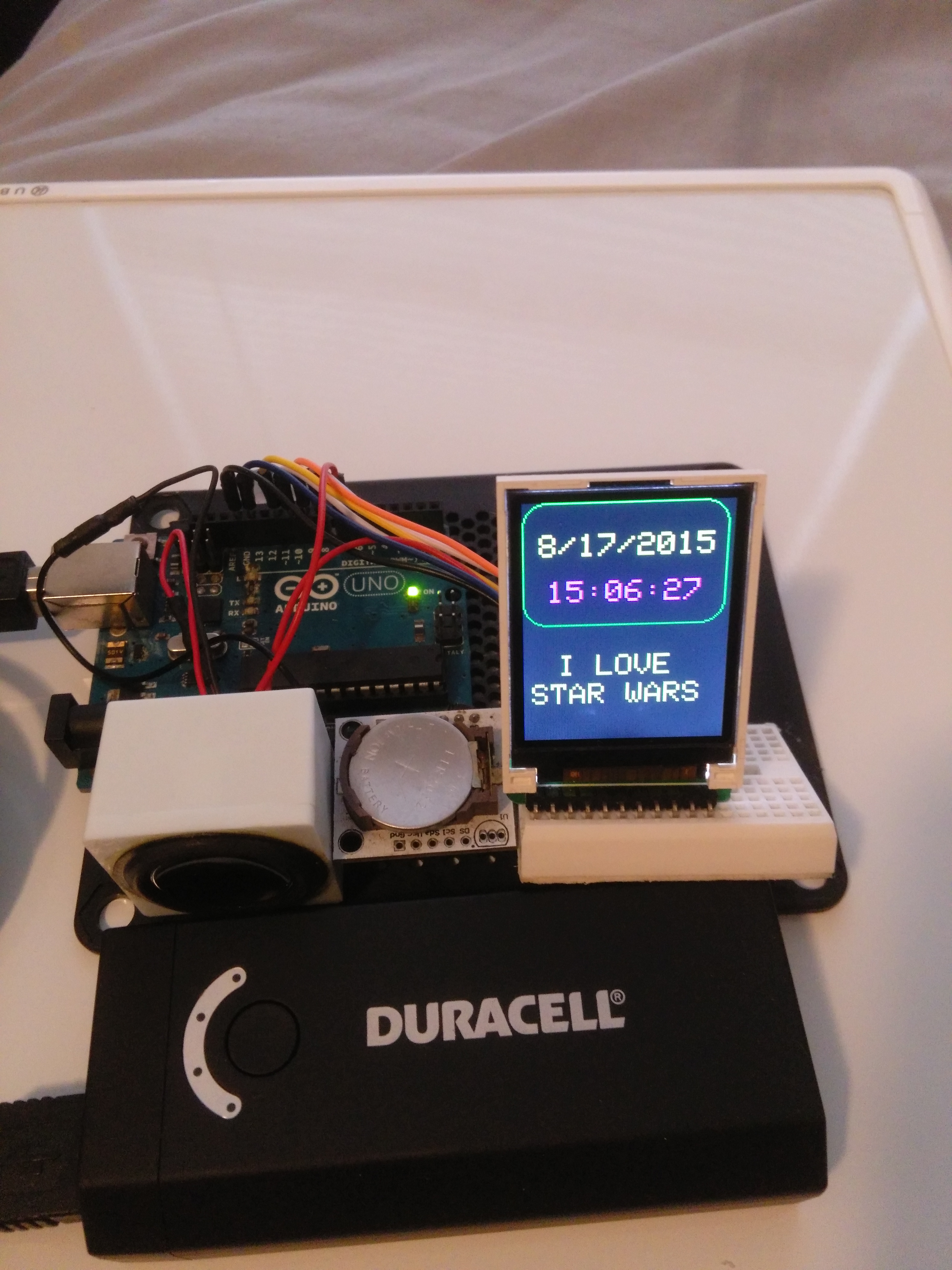
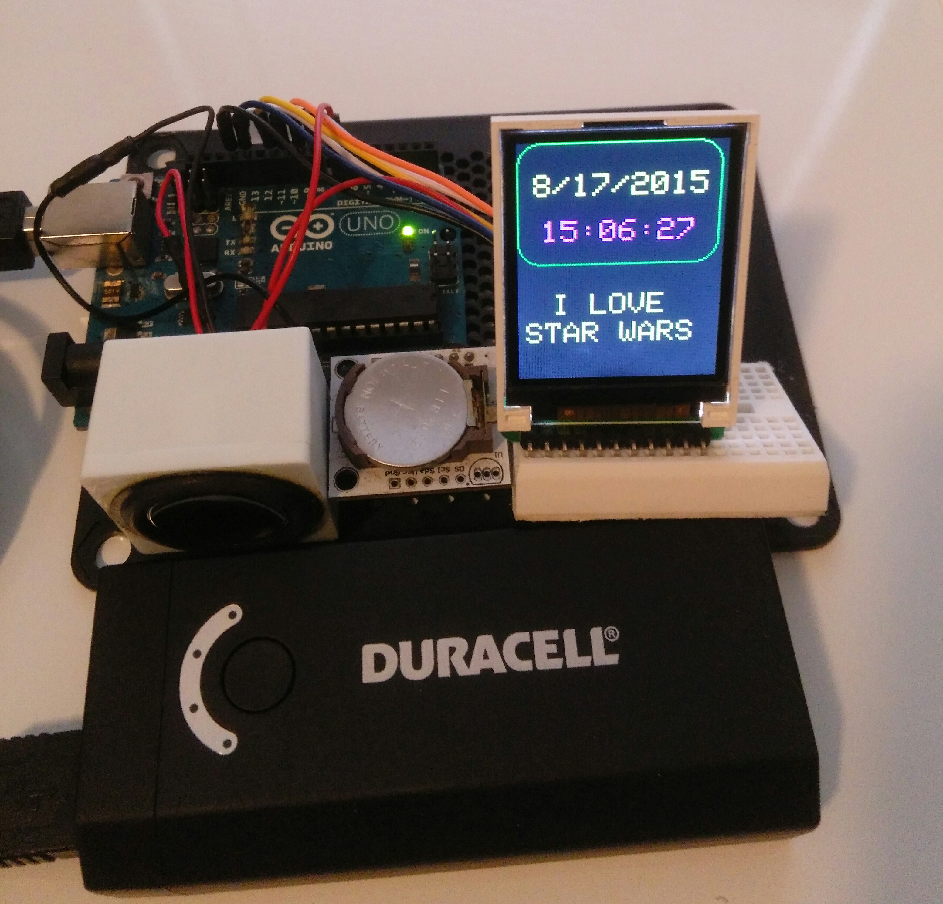
Once you're finished building and testing the hardware, it's time to download the message clock Sketch and load it to the Arduino.
You will notice that the hardware does not include any buttons to set the clock or the messages. We will be doing this by editing the sketch. Once the Date and time, and the time triggered messages are configured, you can run the clock from an external power source. The RTC has a battery that will maintain the time even if the Arduino has no power.
The included .zip file has a folder with the messageclk.ino sketch file and a pitches.h file. make sure both files are copied to your sketches folder. The pitches.h file contains a table that translate frequencies to musical notes, and has to be in the same folder where the main sketch is. A note about the tones; I "borrowed" code for the music from google searches a while back and did not document where I found them, so unfortunately, I cannot give credit to the authors where credit is do.
Before you load the Sketch, you will need to set the dates and times, and the messages you want displayed. In order to do that, you need to edit certain lines in the sketch that control the time triggered display of messages.
To adjust the clock for the first time, we use the following code found under the void setup:
RTC.adjust(DateTime(__DATE__, __TIME__));
This code sets the RTC clock to your computers date and time
The messages(and music tones) are triggered by If statements that use a day and/or time to trigger the event.
The code for these events is found in the void loop
for example the code below displays "MERRY CHRISTMAS" in the message box;
if (now.month()==12 && now.day()== 25){
tft.setCursor(5,100);
tft.setTextColor(ST7735_RED,ST7735_BLACK);
tft.print(" MERRY " );
tft.setCursor(5,120);
tft.print("CHRISTMAS");
An example that shows all the features of the message clock it the happy birthday code. The code below will display "HAPPY BIRTHDAY NAME" in the message box, play the happy birthday melody, and randomly light up the RGB LED color in sync with the tone. the event will happen on the hour for every hour of the day (on October 24th for the example).
if (now.month()== 10 && now.day()== 24 && now.minute()==00 ){
tft.setCursor(2,100);
tft.setTextColor(ST7735_GREEN,ST7735_BLACK);
tft.print(" HAPPY " );
tft.setCursor(2,120);
tft.print(" BIRTHDAY ");
tft.setCursor(2,140);
tft.print(" NAME");
for (int i = 0; i < length; i++) { int rgb = random(4,7);
if (notes[i] == ' ') {
delay(beats[i] * tempo); // rest
}
else {
playNote(notes[i], beats[i] * tempo);
digitalWrite(rgb,HIGH); }
// pause between notes
delay(tempo);
digitalWrite(rgb,LOW);
}
I hope this explanation is enough to get you going. If not place a comment and I'll try to clarify. Remember, the best way to learn is to try to figure things out yourself.
Hope you enjoy making it as much as I did.