Arduino Car
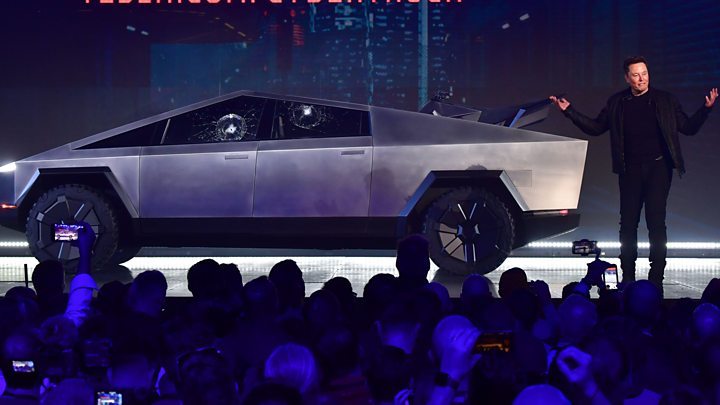
Credit (For The Image Above): BBC.com
You probably might have nothing to do or just want to create something cool, Any way you decide to come on instructables.com and choose this amazing instructable; So now that we are all caught up, let us start. The first instruction (as this is an instructable) is to imagine together; Have you ever thought of making a cardboard car that uses an Arduino to operate, but just don't know where to start; probably not, but now you are thinking about it so here how to make an Arduino Car.
Supplies
These are the following tools you are going to need for the build:
- Laser Cutter (Optional but recommended) (Alternative: Paper Cutter) (x1)
- Paper Cutter (If creating my design inspired by the Tesla Cybertruck) (x1)
- Soldering Iron (Optional but recommended) (Alternative: Electric Tape) (x1)
- A4 Printer (If using Paper Cutter) (x1)
- Pencil (Optional but recommended) (x1)
- Scale Ruler (x1)
- Hot Glue Gun (x1)
Materials you will need for the build:
- 3mm MDF Board (Laser Cutter) / 3mm Corrugated Cardboard (Paper Cutter) (30cm x 30cm or larger) (x1)
- A4 Sheet (If using Paper Cutter or If planning to add headlights in the car) (x1)
- Hot Glue Stick (x1 or more depending on your skill level)
- Arduino Uno Circuit Board (x1)
- DC Motors (x2)
- Led(s) (Optional) (For the headlights of the car) (x3)
- High-Density Foam Board (Black) (30cm x 30cm or larger) (x1)
- 9v Battery (x1)
- L293DNE motor driver (x1)
- Small BreadBoard (x1)
- Wires (x21)
- Wheels (x4)
Creating the Body of the Car
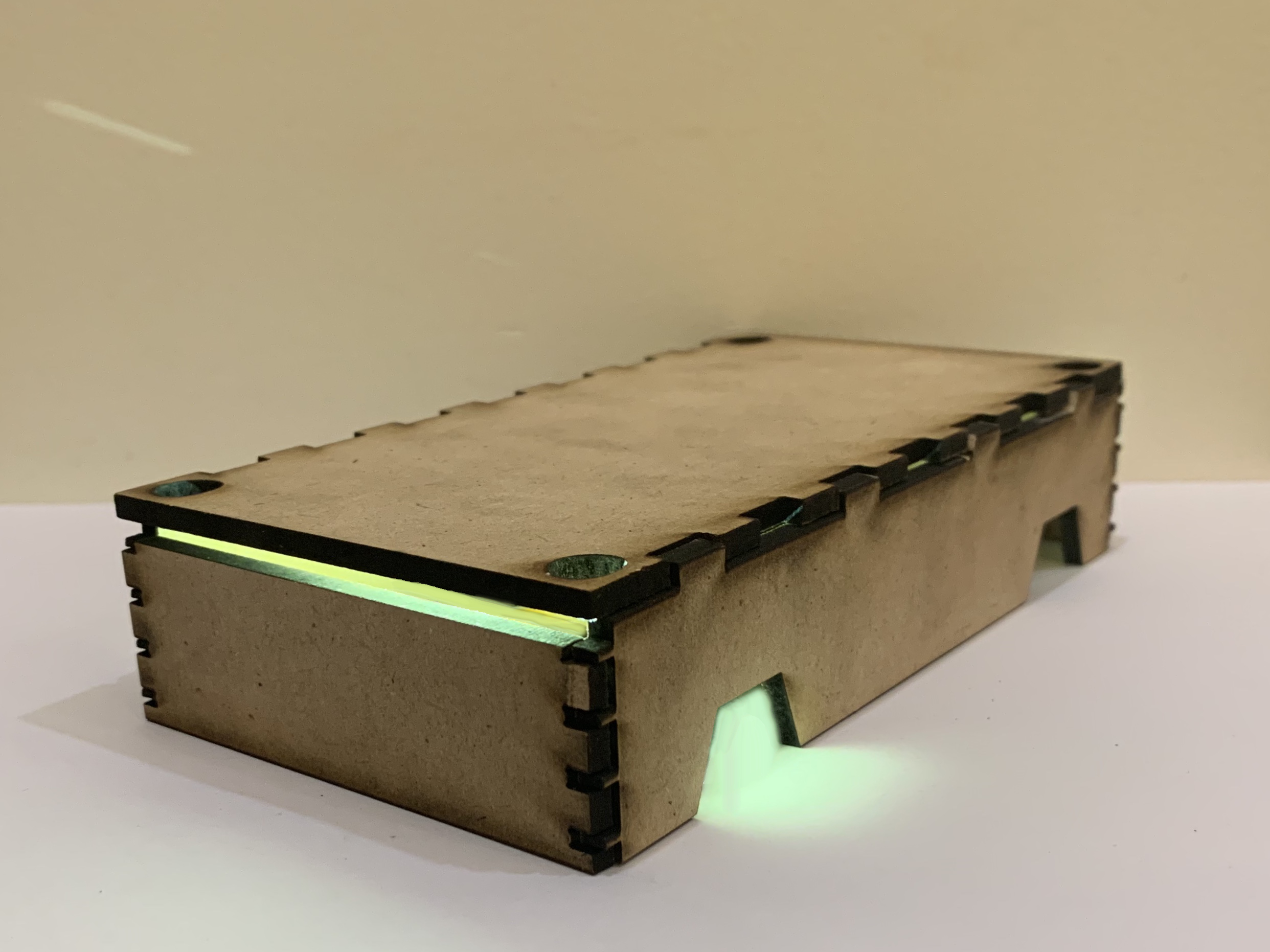
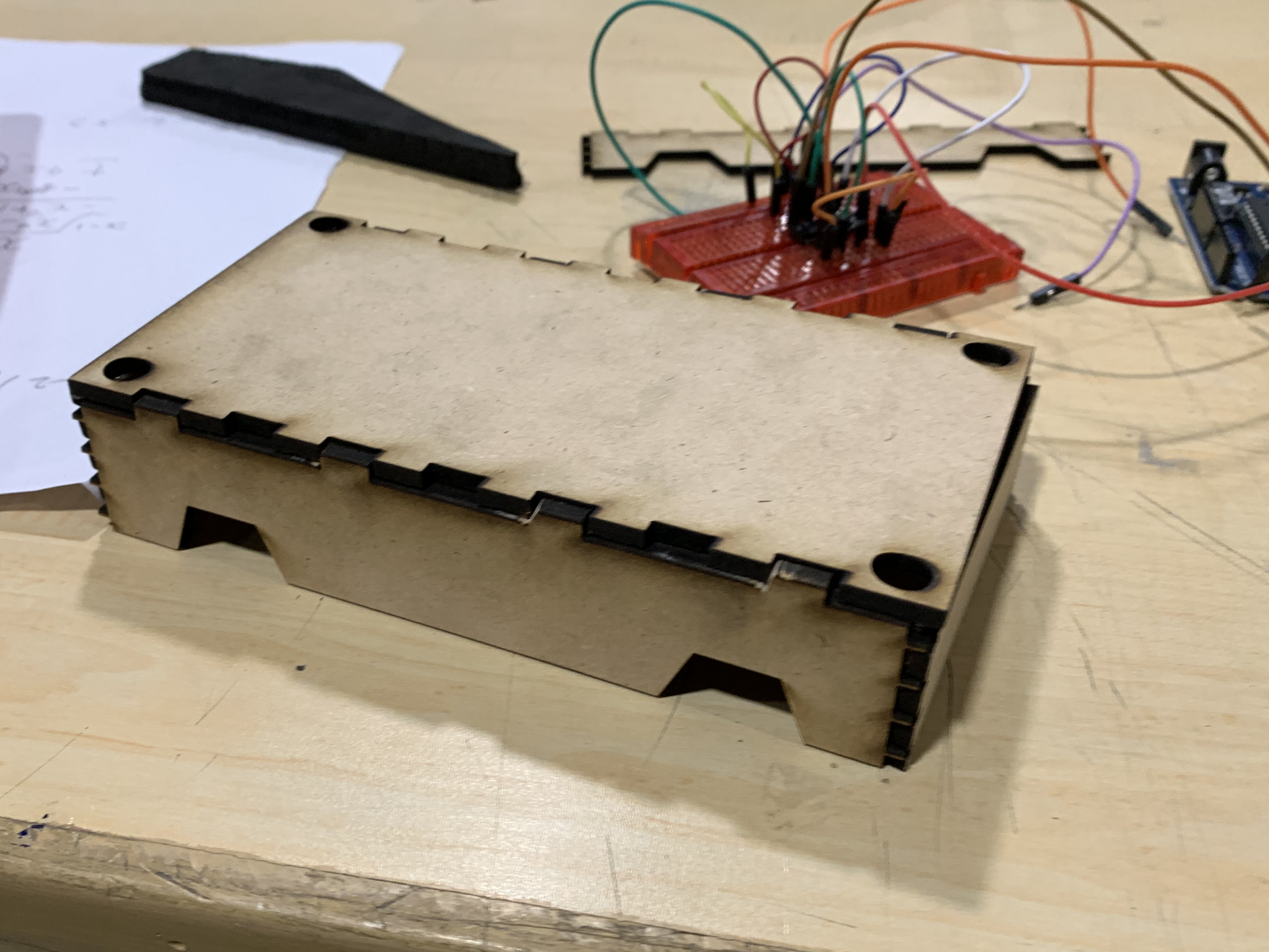
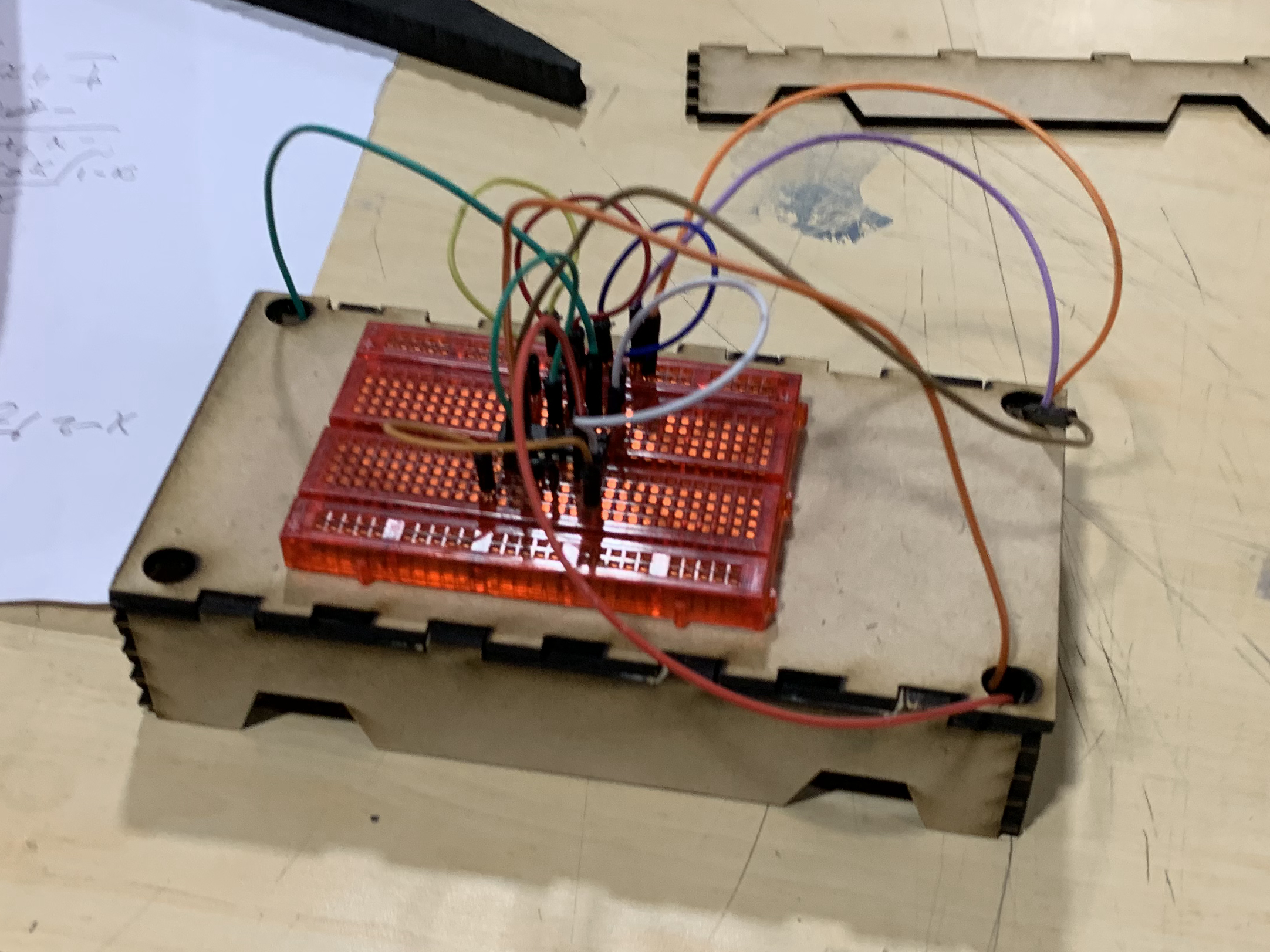
The first step of making an Arduino car is making the car. This step could potentially be the longest or the shortest step, depending on which tool you currently have available. If you are using the corrugated cardboard with the paper cutter, Unfortunately, this is going to take some amount timer and you with the MDF board and the laser cutter, you are lucky as you aren't going to have to cut the cardboard which would take a considerable amount of time more to complete this step unless you are some kind of a professional cardboard cutter. The first step in this step is to go to the bottom of the text and download the three files named "Car.svg", "Car With Measurement.svg" and "Car A4.pdf". Congratulations!!!; you have now already completed the one-third of this step as a whole.
This is the point where the steps for people with different tool diverts. If you are using the paper cutter and the corrugated cardboard to can just go ahead and skip this paragraph as it should be part of the instructions for you, but if you still have time to waste, you can also read this paragraph. If you are using the laser with the 3mm MDF board, you can continue reading. Run your laser cutter software and load the file "Car.svg" which you should have just downloaded. As for reference, also open the file "Car With Measurement.svg" on a photo viewing application and then with the help of the annotations in the file "Car With Measurement.svg" you can then set the accurate measurement of the "Car.svg" file in your laser cutting software. If you aren't aware of laser cutting software, I would recommend LightBurn Software, which is the software that I use for the build. Now that you are done setting the dimension of the file, you can go ahead and send the file to the laser cutter and cut it. For further instruction, skip the start from the paragraph after the following paragraph.
Assuming that you currently have and will be 3mm corrugated and a paper cutter. If you have an accessible A4 printer at home or where ever you are creating this build, You can load A4 sheets in the printer and then can print the file "Car A4.pdf" which is a file that you can use as a template for cutting on the cardboard. After printing, to use the template, you will first have cut out the shape as drawn on the sheet. Following that, you can now place those shapes on the piece of cardboard you intend to cut and then go ahead and cut the cardboard according to the shape you cut out.
Now that you have cut out your cardboard piece, you should ended up with four main pieces and now all you have to do is attach them together which can be seen under this steps tittle. If the finger joint of the pieces falls out easily and is attached loosely you can use hot glue on those joints so the pieces don't fall out. Well done!!!, you are done with the first step of this instructable.
Creating the Circuit
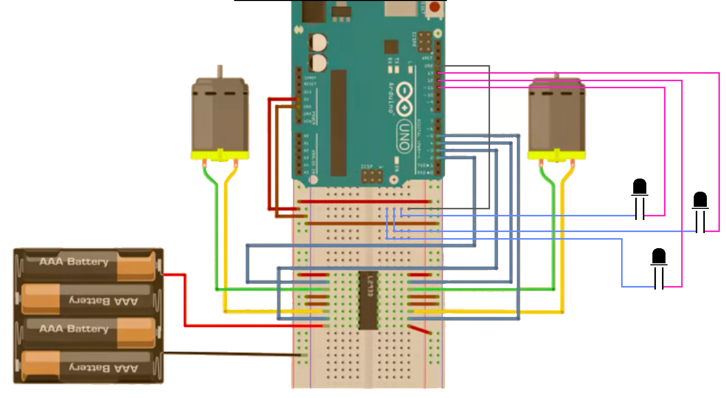
Credit (For The Video Above and The Photo, Which is No Longer The Orginal; Because I Edited it, Thank You For The Original Circuit Design): Mert Arduino
The second step of the instructable is to create the circuit. We didn't have design a circuit and all thanks to the youtube channel named Mert Arduino. Mert Arduino is a really great channel for Arduino related project and if you are interested in that topic, you can go check out his channel at this link after you finish this instructable because "Finish the instructable you have started, specifically this one then you can do whatever you want to do" said the one old wise person.
The video is a step-to-step guide on how to create the circuit but this only exception that this instructable is telling you to do is to do not attach any wires to Arduino, motor and the batteries just yet. Wow!!!; you just completed the second step of instructable; You are almost there to completion of your beautiful car.
Hey, That is just the basic circuit to make the car run; but if you want to commit to creating an amazing car, a car to light up like a beacon in the dark; You can refer to circuit design under the video to add headlights into your creation.
Coding the Arduino
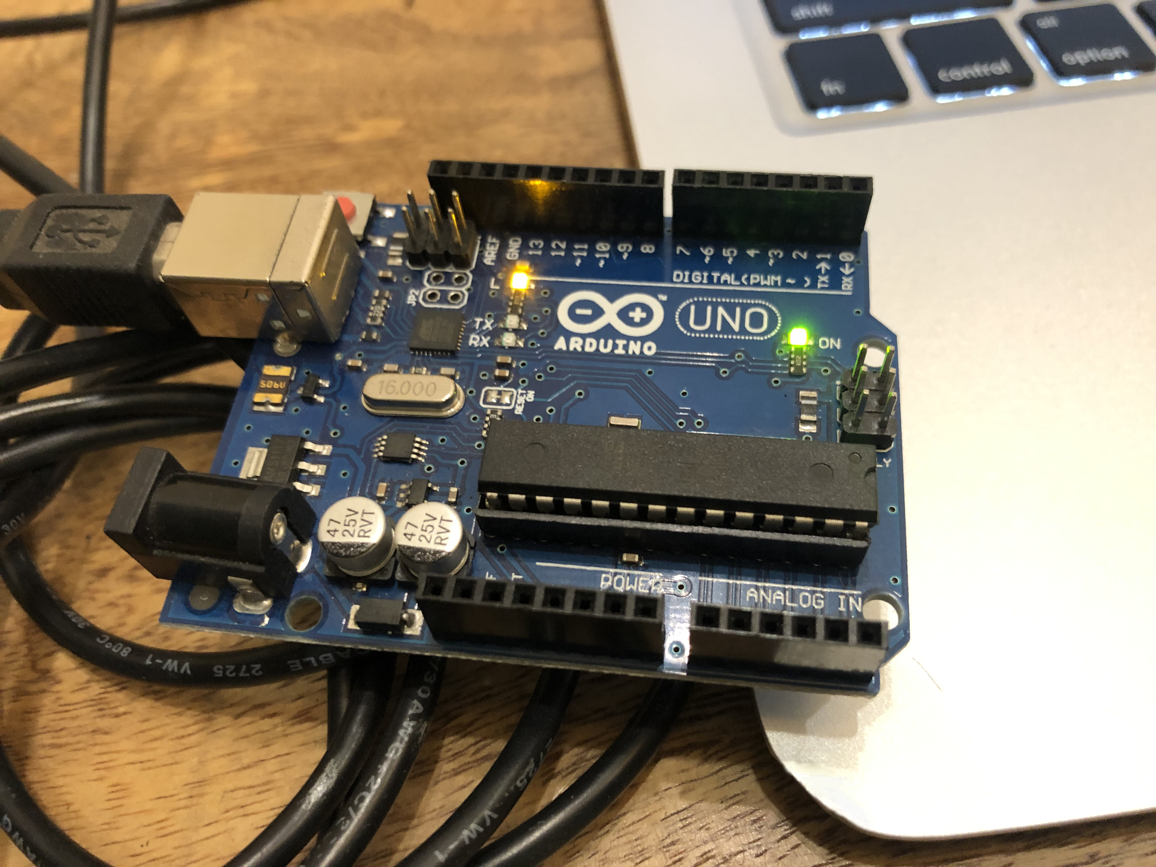
I did have to put some good amount of effort into this step as the source code for the circuit had been deleted. I had to rewrite the code. So if this isn't your first time using an Arduino you can just skip this paragraph but, if it is here is how to set up and run code on an Arduino. First thing you need to go ahead and open your internet browser and download the Arduino IDE, you can do that by just searching "Download the Arduino IDE" on the Google search engine and the first link should be of the download page or else you can go to the website link: https://www.arduino.cc/en/Main/Software and download load the IDE after checking the system requirements meets your system's hardware and software. After downloading the Arduino IDE. You can go ahead to the next paragraph for further instructions.
Run the Arduino IDE application and the plugin your Arduino Uno to your system. For the code, you can just go ahead and download the file "Car.ino" at the bottom of this step and open that file into the application. If you are unable to download the file or the file isn't opening you can just copy the code given below and paste it on a new Arduino file:
int MotorLeftFront = 2;
int MotorLeftBack = 3;
int MotorRightFront = 4;
int MotorRightBack = 5;
boolean CarForward;
boolean CarBackward;

void setup() {
  pinMode(MotorLeftFront, OUTPUT);
  pinMode(MotorLeftBack, OUTPUT);
  pinMode(MotorRightFront, OUTPUT);
  pinMode(MotorRightBack, OUTPUT);

  // You can change the value of the boolean below to change the direction the car will go
  CarForward = true;
if (CarForward) {
CarBackward = false;
} else if (!CarBackward) {
CarForward = true;
}
if (CarBackward) {
CarForward = false;
} else if (!CarForward) {
CarBackward = true;
}
} void loop() {
if (CarForward) {
digitalWrite(MotorLeftFront, HIGH);
digitalWrite(MotorLeftBack, LOW);
digitalWrite(MotorRightFront, HIGH);
digitalWrite(MotorRightBack, LOW);
} else if (CarBackward) {
digitalWrite(MotorLeftFront, LOW);
digitalWrite(MotorLeftBack, HIGH);
digitalWrite(MotorRightFront, LOW);
digitalWrite(MotorRightBack, HIGH);
}
}Now that you have successfully pasted the above or have opened the file "Car.ino" on the Arduino IDE application, the step is to compile the code to check whether there is anything wrong with the code or not. If you don't find an error you can now go ahead and upload the sketch unto your Arduino Uno. If it fails to upload the sketch here are the following thing to can check for troubleshooting the problem.
The first check is to check whether or not you are using the right cable, can the cable send data two way. The second check is if you have properly connected or even connected your system to the Arduino. The third check is to see if any light turn on the Arduino Board. If not the board isn't receiving enough power through the cable or the board doesn't work and for the four and the last check, because I can't think of anymore way to troubleshoot this issue; is to check in the Arduino IDE, Go to "Tools" then "Port" and then make sure that the port is set to the Arduino. Great Job!!!, you finished uploading the code to the Arduino marking the end of this step. But, wait if you are planning to put the headlights in the car and wondering, why, why, why aren't LEDs lighting up; Don't worry it is not a scam.
You have just uploaded the wrong code which is not a Great Job!!!. Me not telling you earlier is also not a Great Job!!!, but I am at least telling you now. Better late than never. Ok let us stop with this conversation that isn't heading anywhere and wasting your time, I was just trying to get into the flow of writing; Anyway, if you made the headlight circuit in the previous step download the code titled "LightningCar.ino", it includes the code to light the LEDs attached to the circuit.
Putting Everything Together
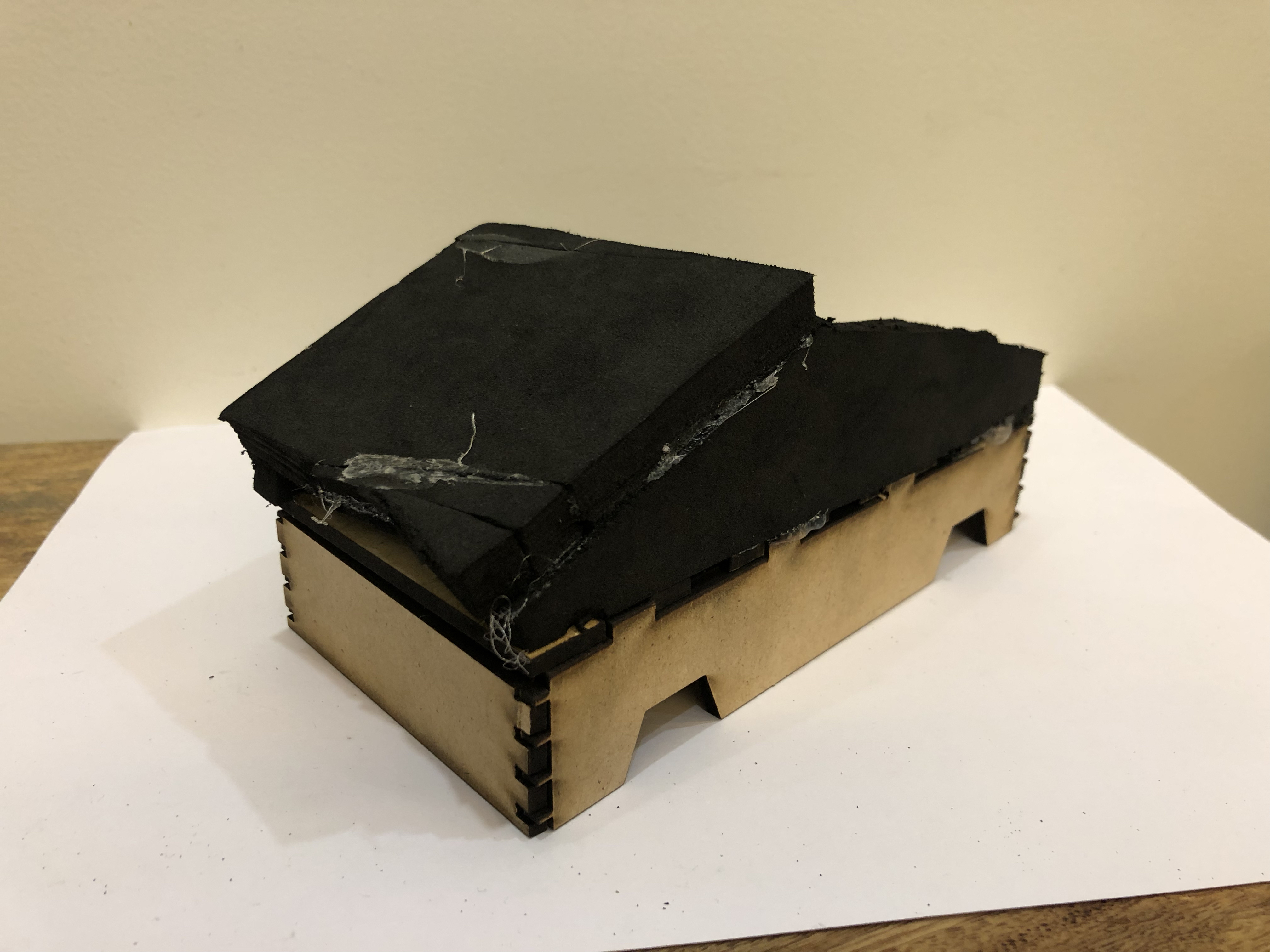
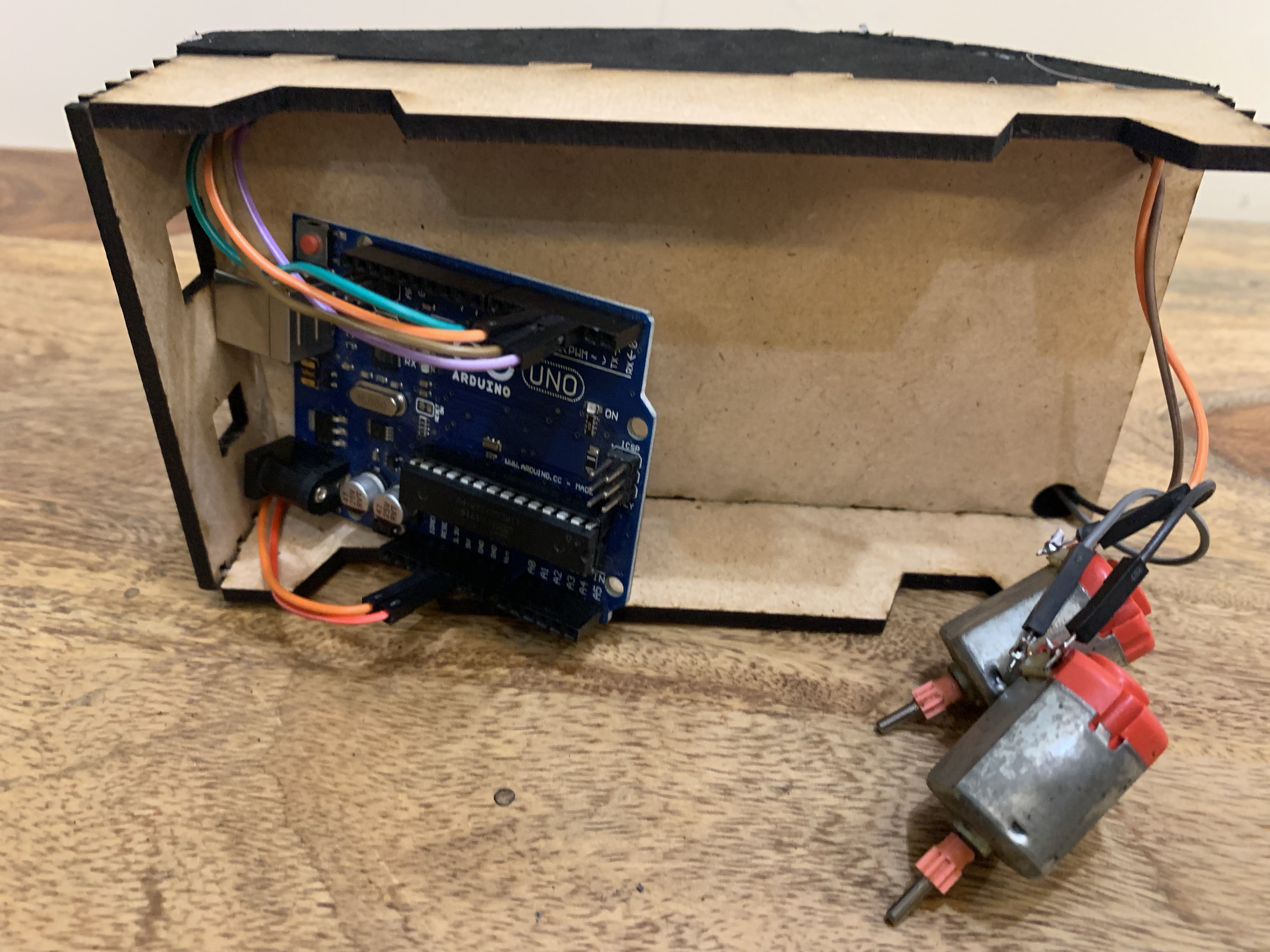
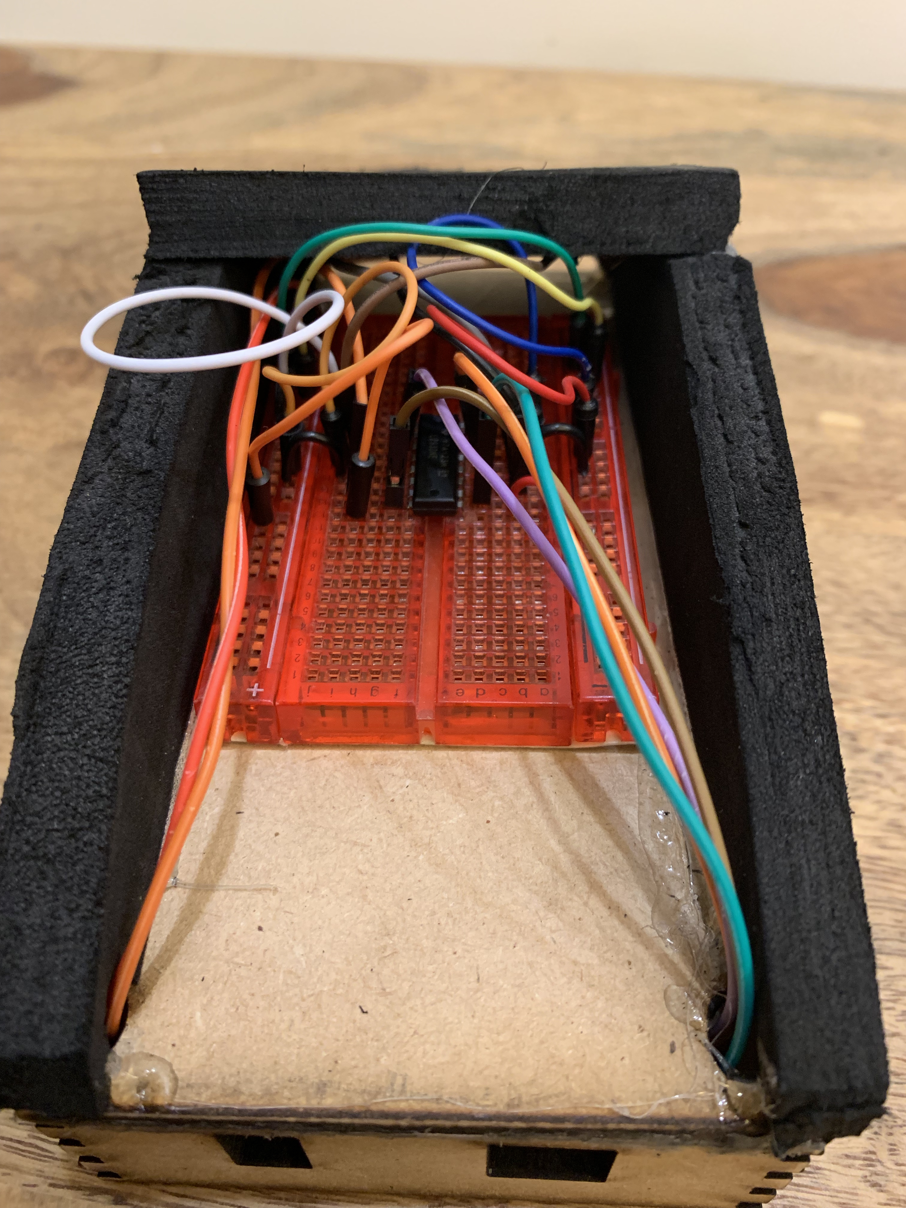
Hey, You have done a lot of work till now; so, if you are getting burnt out or tired go and, take a break; Maybe chill and come after a few hours or even after a day or two. Come with a fresh mind ready to work, but just don't forget the main part of the break; coming back.
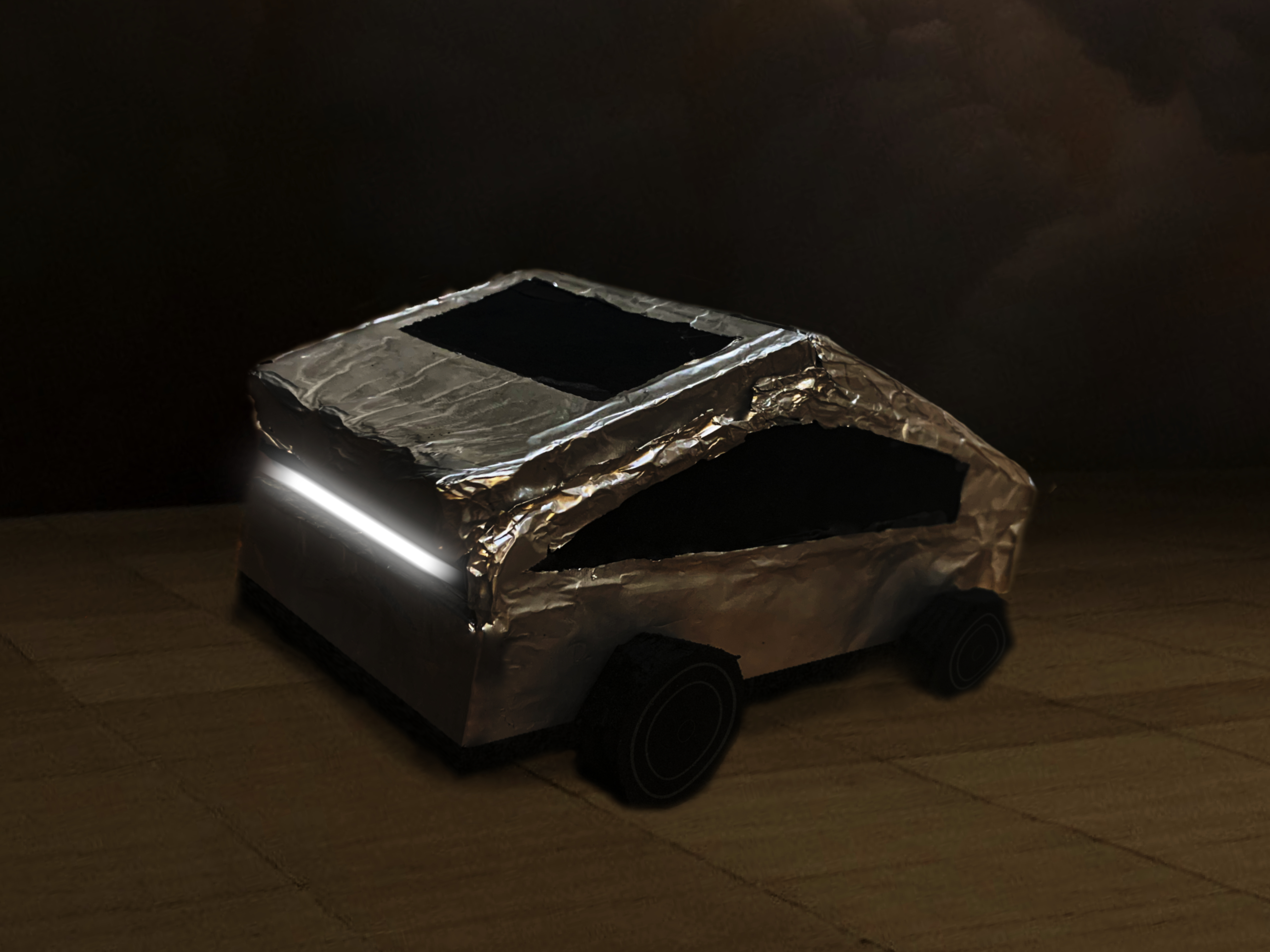
Ok, hope you had a nice break; let's get back to where we left. We are finally, making the car!!! Till now we were just setting up and creating the different parts/components of the car but in this step, we are actually going to make the car. I know that in the image it looks a little messy, but not be worried that is not how the car is going to look like in the end. I am saying car too many times, I will avoid using that term. This and the following step allows you to customize your car. You can notice the top of the car's body still has some finger joints that aren't attached to any other joint; It is for the reason that you could design your own top of the car and attach it to joints which the help of a paper cutter or the laser cutter. I decided to create a design inspired by the Tesla Cybertruck; when in the process of creating the product, one of my classmates asked me "Are you creating a Car or a truck?", I was like "Yes", then they were like "Cybertruck", then I was like "Why not?" then I made it; wasn't that an interesting story?, maybe I might even write a book on it; Just kidding, As I was saying I made the car design inspired by the Cybertruck, so if also think that creating a design inspired by the Cybertruck is a cool idea, you can follow ahead but if not. I am sorry to say our this is where our journey ends until the paragraph after the next until which you can design the top of the car and build it, but don't attach it because we have installed the circuit into the car. You, who is design there own top to go to paragraph after the next and first install the circuit because then based on that you can design your top so it doesn't interfere with any components positioning and, we who are creating the Cybertruck inspired design lets to go to the next paragraph. I don't know why I am repeating word but I am trying to avoid them; let's go.
If you are not good or also might be good at imagining or visualizing in your head, you might need some materials to sketch out the shape of the top of the car. We, with the help paper cutter, have to cut out a triangle with the following requirements on the high-density foam board. You have to create two isosceles obtuse triangles with the base length of 16cm and the base should be from vertex A to B. The height of the triangle is 3cm and this highest point should be vertex C. Vertex C is directly above the 8cm from vertex A to B or B to A. The Angle for Vetex A and B should be 20°and the angle of the vertex C should 140°. The length of A to C and B to C should be 8.5cm. I hope that was to complex and you understood what the triangles should be like. If your brain is aching, go take a 5min break and come back. Now that you have the two triangles, we have to cut two more rectangle pieces of the foam board with a height of 8.5cm and length of 8cm. You made it past this half of the paragraph, 👍 (That's the first time I have ever used an emoji on a documentation, and it's for you :). Take the two triangles and place each one to the left and right of the length of the car length. Check If it covers the holes for the wires on the four corners of the car's body. Well if it does, take the paper cutter and small caves in that part of the triangle that would allow the wire to pass through into the side of the top the car. Now take the hot glue gun, put hot glue on the left and of the right of the car's body and then place the triangle on the glue. We are almost done with the top of the car but first, we have installed the circuit in the car after which we can cover the top with the two rectangle pieces of foam board that we cut out earlier.
Take the soldering iron and solder two wires to each motor and if creating the headlight also solder two wires to each LED. The take wires that need to be attached to Arduino and then attach the end the need to be attached to be the Arduino, basically don't attach the other end to beard board, don't attach anything to the beard board just yet. Now from the bottom of the car pass the loose wires through the holes in the corner of the car's body. Make sure that you can then easily place the Arduino in the position the cut out for the ports and the wires for the motors and the LEDs should go from the front holes of the car's body. Now you can take a slice of the foam board and paste it to the surface of the bottom of the body of the car. Don't cover the holes for the wire but paste it around it. You can now paste the Arduino to the bottom of the car aligned with the holes for the ports on the Arduino. Now you can stick the breadboard on the top of the car's body and then build or create the circuit with reference to circuit design in step 2. You can now paste the two rectangles on the two sides of the triangles to cover the top if you were creating the design inspired by the Cybertruck, or paste on your top for the car which you designed. We did it, we are on the second last step just one step and we will be done with this build.
Final Additions
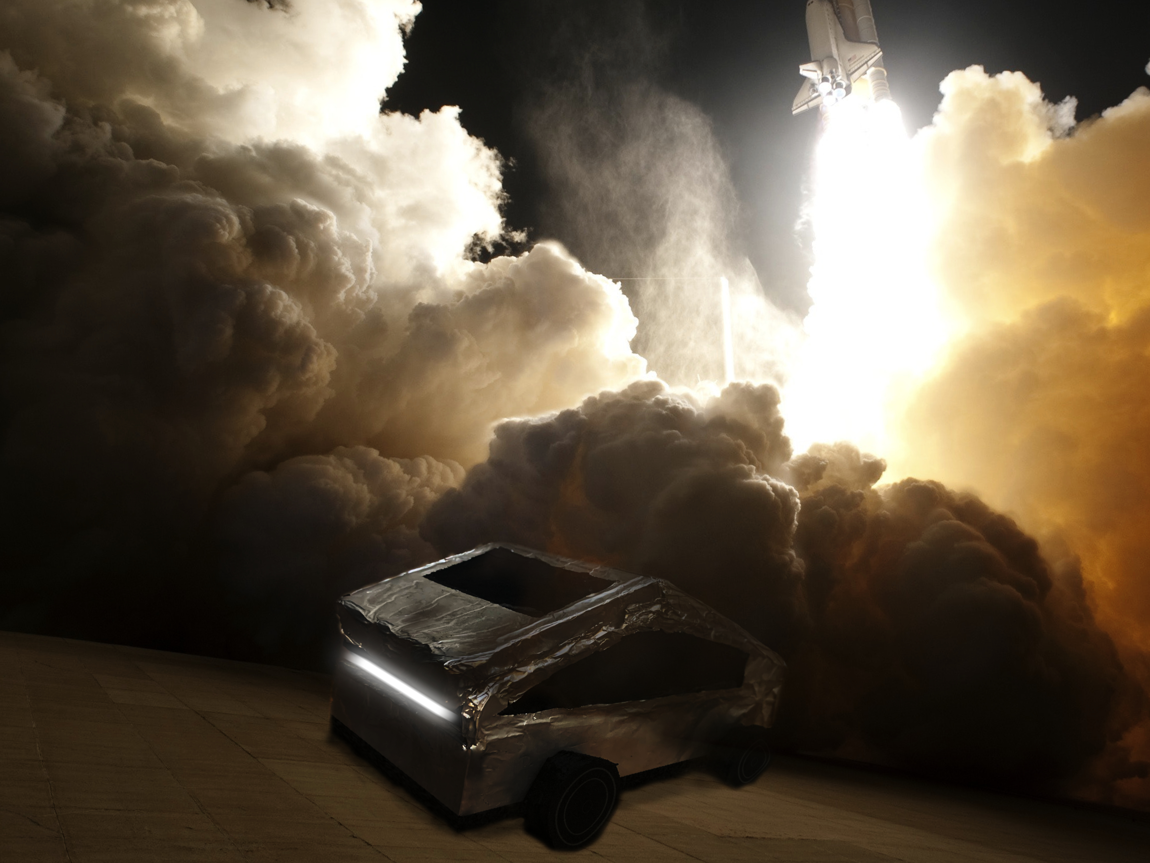
It's been a great journey and we are reaching the end of it, I would really like to thank you for choosing this amazing build. The last step, let's finish this. If you were creating the car with the headlight you can equally space the three LEDs and past it to the bottom of the surface of the car's body. They should be a slot to the light to pass through try to place the led as close as the slot but don't allow the LEDs to pop out of the body. From the outside of the body of the car, you can stick a strip of paper that you can cut out from the A4 sheet of paper and then stick that strip of paper over the slot for the light. Now cut out strips of the foam board and keep stacking them and stick the bottom the car's surface until the motors can be stuck to stack to be at the height of the cut for the wheel. Do it for both of the motors for each side of the car. For the back wheels of the car, you have to do the same thing of the stack till the height of the wheel but the just add one more strip or more so that it is just above the minimum height of the wheel cut out. Now try to make a strong and thin roll of paper the length a little longer than 8cm and then, push the roll through the stack to be position so that it is exactly equal distance for the sides and the top of the cutout for the wheel. Now can attack wheel to the ends of the motor and two sides of the roll and you are done!!!!!!!!. Did it!!! We did !!!!!. The product might still look a little bare so you can go ahead and decorate it, I used to glue to completely wrap aluminum foil around the car and cut out windows and the windshield and does it look amazing. Hope you enjoyed this build. You can see the pictures of the end product in the next step. It looks beautiful. Thank you for your time.
Appreciating This Beautiful Creation
