Arduino Buzzer/Light Temperature Alert Sensor Prototype
by aca1999 in Circuits > Arduino
2197 Views, 0 Favorites, 0 Comments
Arduino Buzzer/Light Temperature Alert Sensor Prototype
.jpg)
The prototype for this was done for a class assignment, but I've written down how you could try doing it yourself. This is my first instructable!
You could even try placing the final hardware collection in something else that could be worn or use it as a passive thermometer in your home, in my instance I'm putting it into a hat, hence the light strip.
The goal of this project was to, in theory, create a sensor that could be worn by an elderly person that would alert them when the outside temperatures were getting too high. It becomes more difficult to regulate temperature as you age and heat-related deaths aren't uncommon in southern parts of the world. The sensor would be something that could be worn; in this instance, I decided to place it inside a hat since there is space to place the components within the bulge of the hat and because there would be an easy place to apply a light strip for an alert. This instructable will show you how examples on how to arrange the sensors, code, and wires, but the use of the final product is yours to decide.
Supplies
I recommend amazon for buying any of the little sensors and a dollar store for everything else.
- TMP 36 Temperature Sensor
- Arduino Uno
- Arudino Passive Buzzer Module- I used KY-006
- Breadboard, any size is fine, I used a half size.
- Neopixel light strip, I used an Alitove WS2812B 3.2 ft strip.
- Breadboard Jumper Wires- 10-20 would be best.
- Soldering Iron and something to clean it on, I used a steel sponge
- Solder, of course
- 6x8cm Prototype PCB Printed Circuit Board
- 1000 µF, 6.3V or higher capacitor
- 300 to 500 Ohm resistor
- USB Cable 2.0 Type A/B
- Solid core wire
Gather Supplies
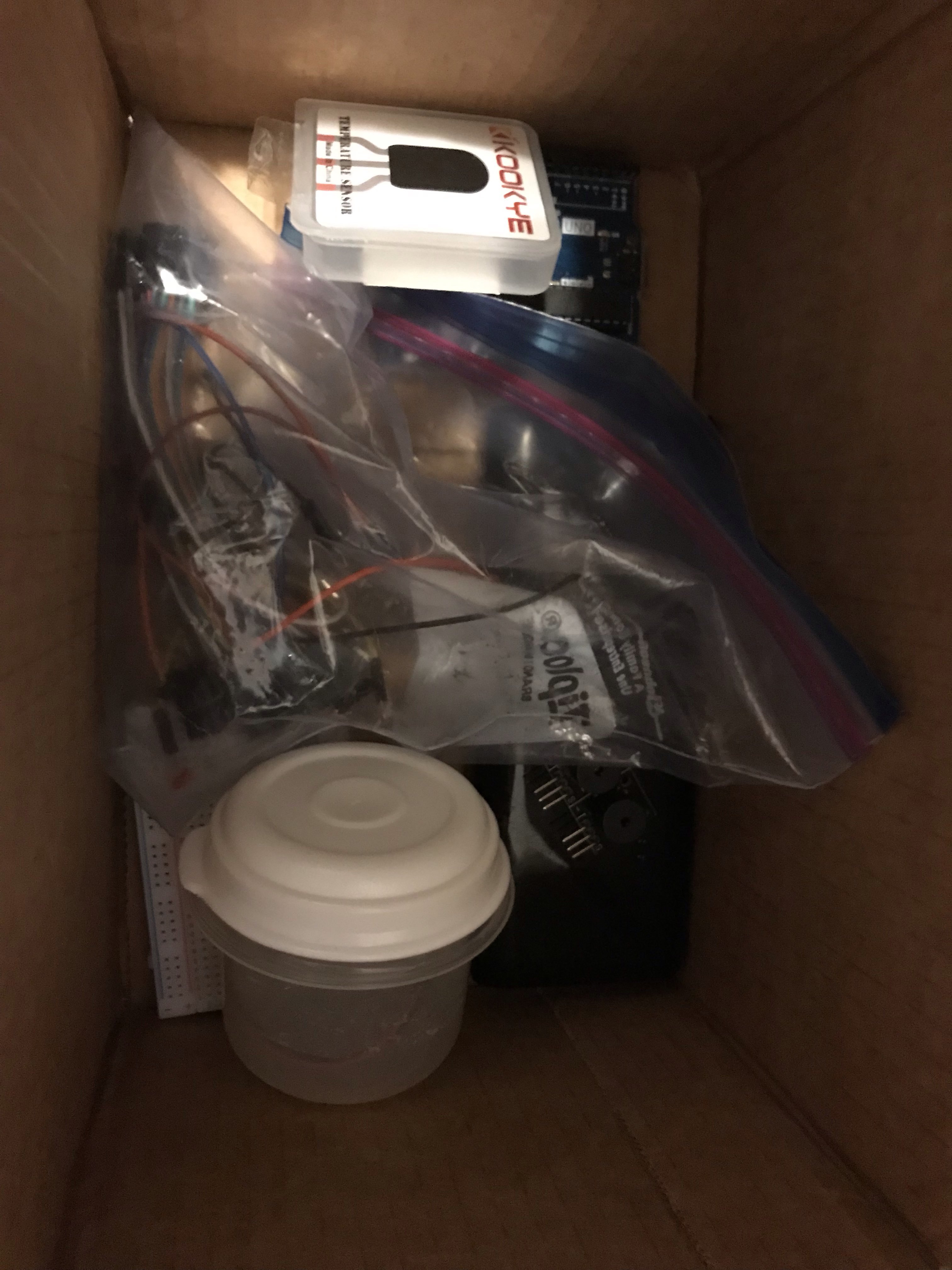
The obvious first step; it's easiest to begin once you have everything assembled. Though I would recommend storing them in a better manner than my image, which is just to show everything gathered together.
The Code, Part 1

Once you have everything, you'll want to pull up Ardunino's Open-Source Software to begin. The code you'll be using has to have three goals:
- Read the temperature.
- Respond to the temperature if it is above a certain set amount. If not, it needs to remain showing the 'safe' alert.
- Respond with a Light alarm and a Buzzer Alarm.
To begin, you'll want to find a code for the TMP36, if you're not particularly good with coding like I am. What I did was search the Arduino libraries.
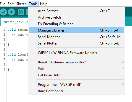
If you don't know how to do this, you go to the 'tools' tab and hit 'manage libraries.' (See image.) To find the code you're looking for, you'll search the name in the search bar- for this, search TMP36.
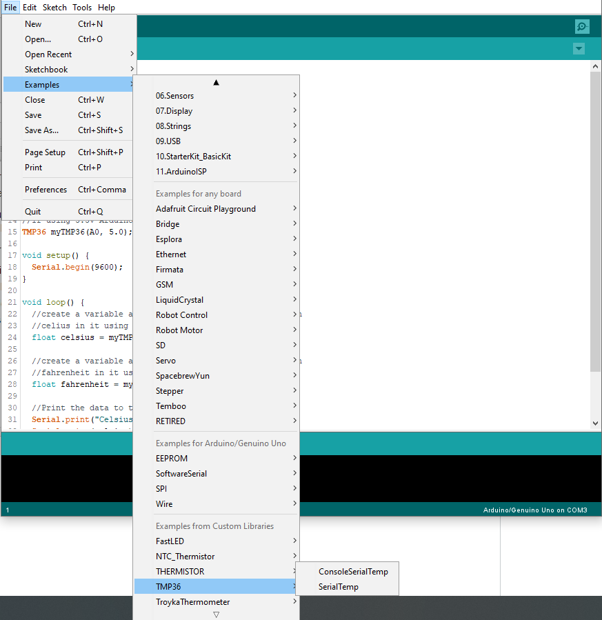
The code I found and used is called TMP36 by Isaac100. When searching the libraries, it appears like it does in the image. To open this code, you'll go to the 'file' tab and scroll down to 'Examples' where the TMP36 example codes are and open 'SerialTemp.' This will be what works your TMP sensor. You will need the downloaded library to actually use the code as it includes other libraries within.
Take note of what analog pin you use. The original code uses A0, but you can set it to whatever you want.
The TMP36
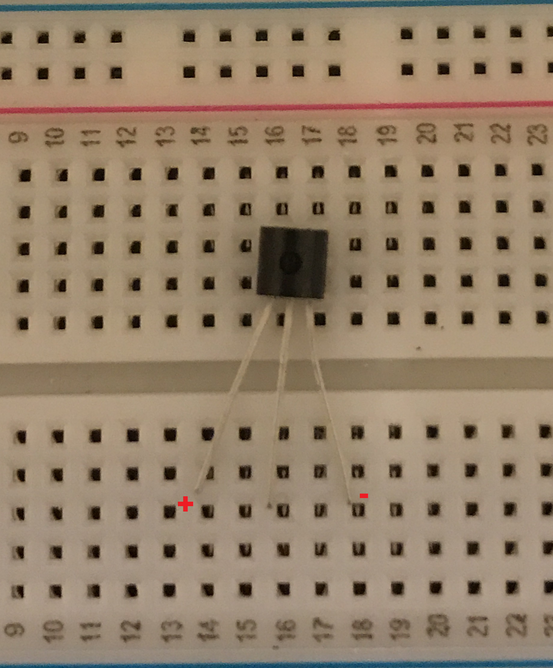
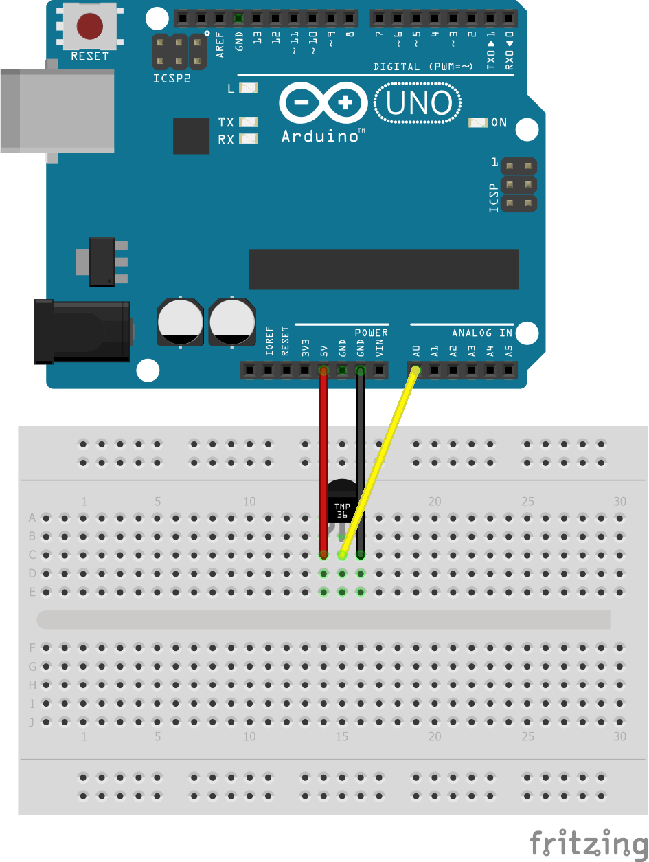
Once you have your code, you want to test this basic code to make sure your sensor is working correctly before moving on.
The TMP36, with the flat side outwards and the circular part towards you, has the positive power pin on the left and the negative ground pin on the right. The middle is the data, or analog pin that you've chosen.
Using your breadboard, connect a jumper cable to each leg and to the arudino as shown. In the example image, orange is power, yellow is data, and black is ground.
Connect your arduino to your computer using the USB cable. Make sure you have the Arudino Uno selected in the Board tab under 'Tools.'
Hit the arrow upload button, and so long as you haven't toyed with the code yet, the TMP will start collecting temeprature information. You can see this information by pulling up the serial monitor (the hourglass icon in the upper righthand corner.) You can usually tell if it's working if you know the average temperature in your house. If you touch it, the temperature reading will go up. If you haven't touched the code and it's not reading correctly, it's possible the TMP sensor is faulty. Do some fiddling around.
The Code, Part 2

Next, you'll be checking the buzzer code. The code I used is from this page on arduinomodules. You'll copy and paste the code into a new arduino sketch so you can test it, first.
You can also copy it below (credit to the author Hugogiusti.) You can change the buzzer control pin if you'd like.
int buzzer = 8; // set the buzzer control digital IO pin<br>
void setup() {
	pinMode(buzzer, OUTPUT); // set pin 8 as output
}
void loop() {
	for (int i = 0; i < 80; i++) {  // make a sound
		digitalWrite(buzzer, HIGH); // send high signal to buzzer
		delay(1); // delay 1ms
		digitalWrite(buzzer, LOW); // send low signal to buzzer
		delay(1);
	}
	delay(50);
	for (int j = 0; j < 100; j++) { //make another sound
		digitalWrite(buzzer, HIGH);
		delay(2); // delay 2ms
		digitalWrite(buzzer, LOW);
		delay(2);
	}
	delay(100);
}
KY-006 Passive Buzzer Module
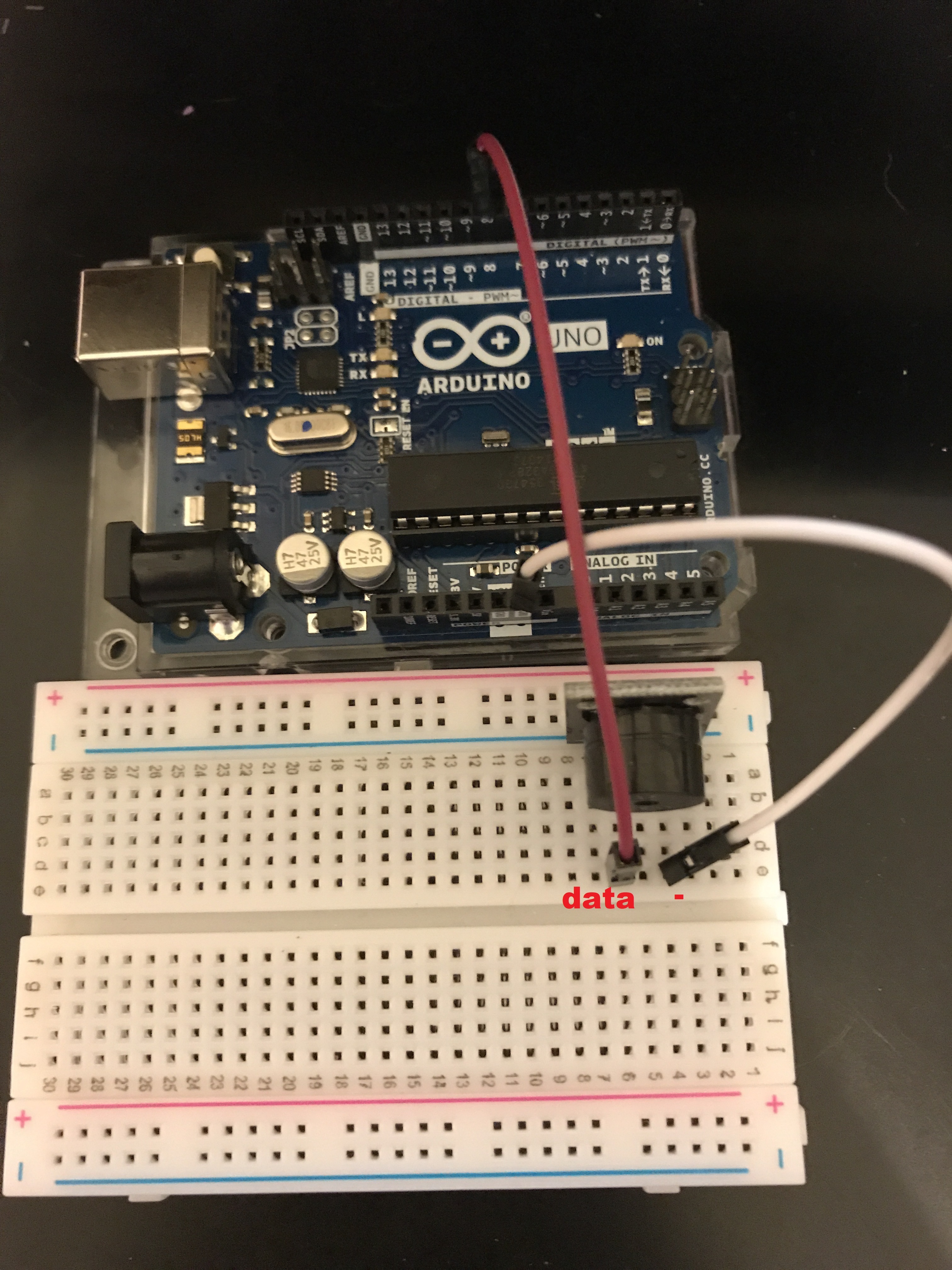.jpg)
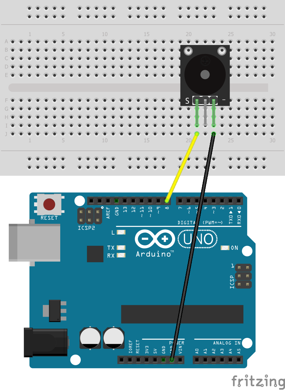
You don't need to connect all three pins for the module to work. The buzzer is set up a bit oddly, and the middle pin isn't needed. With the round part facing you, the left pin is the data pin, which is connected to 8. The rightmost pin is the ground. The middle pin isn't used.
If connected properly, it will buzz in two different tones.
The Code, Part Three

Finally, we need the code for the neopixel light strip.
Returning back to the arduino libraries, you'll search FastLED.
The library you want is FastLED by Daniel Garcia.
Once added, you want the FastLED example titled 'Blink.' You'll be deleting a lot of lines of the code and adding how many neopixels you want in NUM_LEDS, but for now, there's just one.
In the lines that say,
leds[0] = CRGB::Red
You can put in simple colors such as Yellow, Orange, Blue instead of red if you want a different color.
The LED Strip
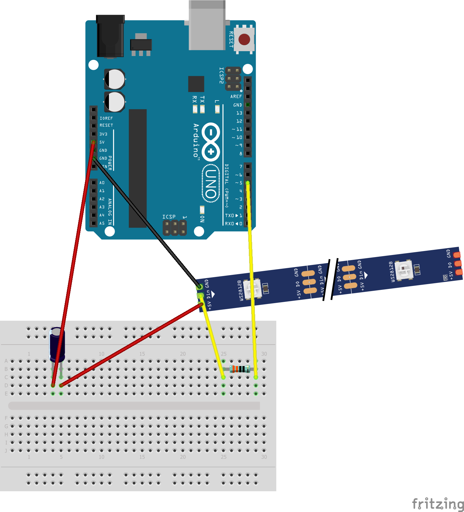
This is where you will be using your capacitor and resistor. Following the adafruit Best Practices, you want a 1000 µF, 6.3V or higher capacitor and a 300 to 500 Ohm resistor.
The schematic is just an example of how to connect them. The resistor needs to go on the data line, the data pin for this particular code being 5. The capacitor needs to go somewhere between the power and ground lines. Make sure everything is wired before you test it. If it's working correctly, the first LED will blink.
Combining Codes
Now, you need to combine your codes.
You want to make sure everything above void setup is compiled. The number of LEDS I used in this example is 13, but you can change it to what you'd like. You can also change the data pins to whatever you prefer.
#include <br>#include
#define NUM_LEDS 13
#define DATA_PIN 5
TMP36 myTMP36(A0, 4.1);
float temp;
int buzzer = 8; // set the buzzer control digital IO pin
int ledPin = 13;
int tempPin = A0;
CRGB leds[NUM_LEDS];
Your void setup should look like this:
void setup()
{
  Serial.begin(9600);
  pinMode(buzzer, OUTPUT); // set pin 8 as output
  //  pinMode(ledPin, OUTPUT); // set pin 8 as output
  FastLED.addLeds(leds, NUM_LEDS);
  lightReset();
}
You'll move the temperature code in the void loop, since it's what's being done over and over again. For the light and buzzer to go off in response to the readings, this needs to be the only thing in the loop.
void loop() {
  float celsius = myTMP36.getTempC();
  float fahrenheit = myTMP36.getTempF();
Serial.print("Celsius: ");
  Serial.print(celsius);
  Serial.print(" Fahrenheit: ");
  Serial.println(fahrenheit);
  delay(1000); }
If you'd like to test everything, you can put the loop functions of the two other codes under this loop, but if you'd like them to be functions that react in response to certain temperature readings, continue forward.
You'll be adding your functions next.
Adding If-Then Statements and Void Functions
Now that you have the readings and a statement that will do something in reaction to those readings, you need to put in the functions for what that 'doing something' is.
You need to place your functions beneath the void loop.
For the buzzer, you simply paste the code in with a void function name before it. I used buzzerHelper.
void buzzerHelper() {for (int i = 0; i < 80; i++) {  // make a sound
		digitalWrite(buzzer, HIGH); // send high signal to buzzer
		delay(1); // delay 1ms
		digitalWrite(buzzer, LOW); // send low signal to buzzer
		delay(1);
	}
	delay(50);
	for (int j = 0; j < 100; j++) { //make another sound
		digitalWrite(buzzer, HIGH);
		delay(2); // delay 2ms
		digitalWrite(buzzer, LOW);
		delay(2);
	}
	delay(100);
}
Next, the light code. I named it lightHelper. Again, you just need to copy and paste.
void lightHelper() {
leds[0] = CRGB::Red;
FastLED.show();
  delay(500);
  leds[0] = CRGB::Black;
  FastLED.show();
  delay(500);
}
Now, you want these functions to occur if a certain temperature is reached, so you need an If-Then statement.
Right now, I'm setting the maximum temperature to 90. I'm leaving an else statement in for later.
if (fahrenheit >= 90) {
    /* if true, do this */
buzzerHelper();
lightHelper();
  }
  else  {
//    /* if true, do this */
//space here for future void functions
 }
Now the two functions will occur if the temperature is found to be greater than or equal to 90. If it ISN'T greater than or equal to 90, it won't do anything.
If you want it to do something, then you need to add more functions.
Since an alert shouldn't buzz when everything is fine, we'll just add another light function that flashes blue and flashes slower.
Below your lightHelper, add a new void function.
Changing the delay changes the speed of which the neopixels change color, so the flash will be slower.
void lightWaiter() {<br>leds[0] = CRGB::Blue;
FastLED.show();
  delay(900);
  leds[0] = CRGB::Black;
  FastLED.show();
  delay(900);
}
Finally, go back and put this in your else statement.
else { <br>lightWaiter(); <br>}You can go and change the number of LEDs or add multiple void functions for different temperatures if you'd like, but this is just an example.
If you'd like to add more than one LED, you need to add it into the code. You may add as many as you want, but for the example it's just one.
For example, if you want two LED pixels to light:
void lightHelper() {<br>leds[0] = CRGB::Red;
leds[1] = CRGB::Red;<br>FastLED.show();
  delay(500);
leds[0] = CRGB::Black; <br>leds[1] = CRGB::Black;<br>FastLED.show();
  delay(500);
}
Arranging Sensors
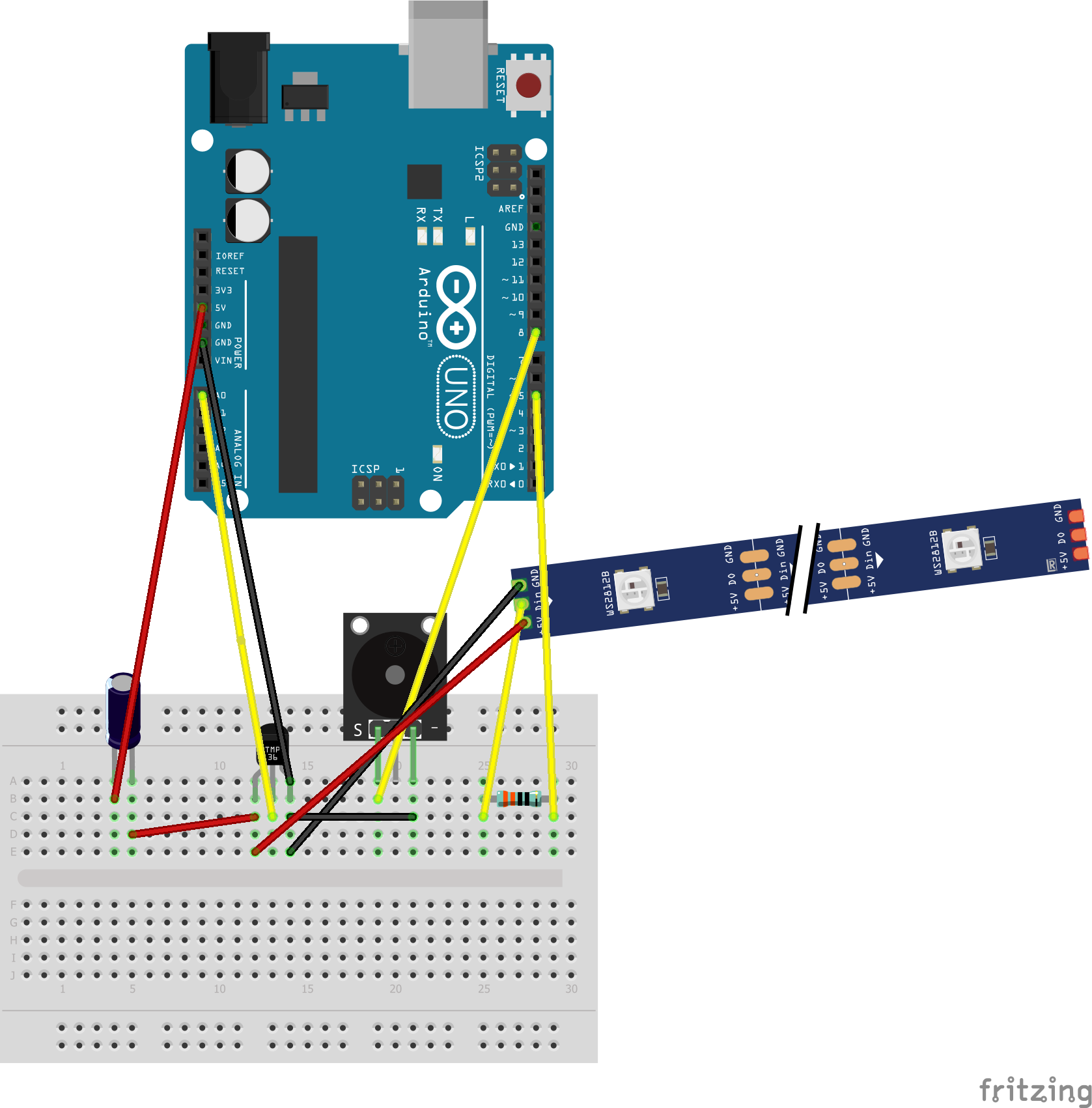

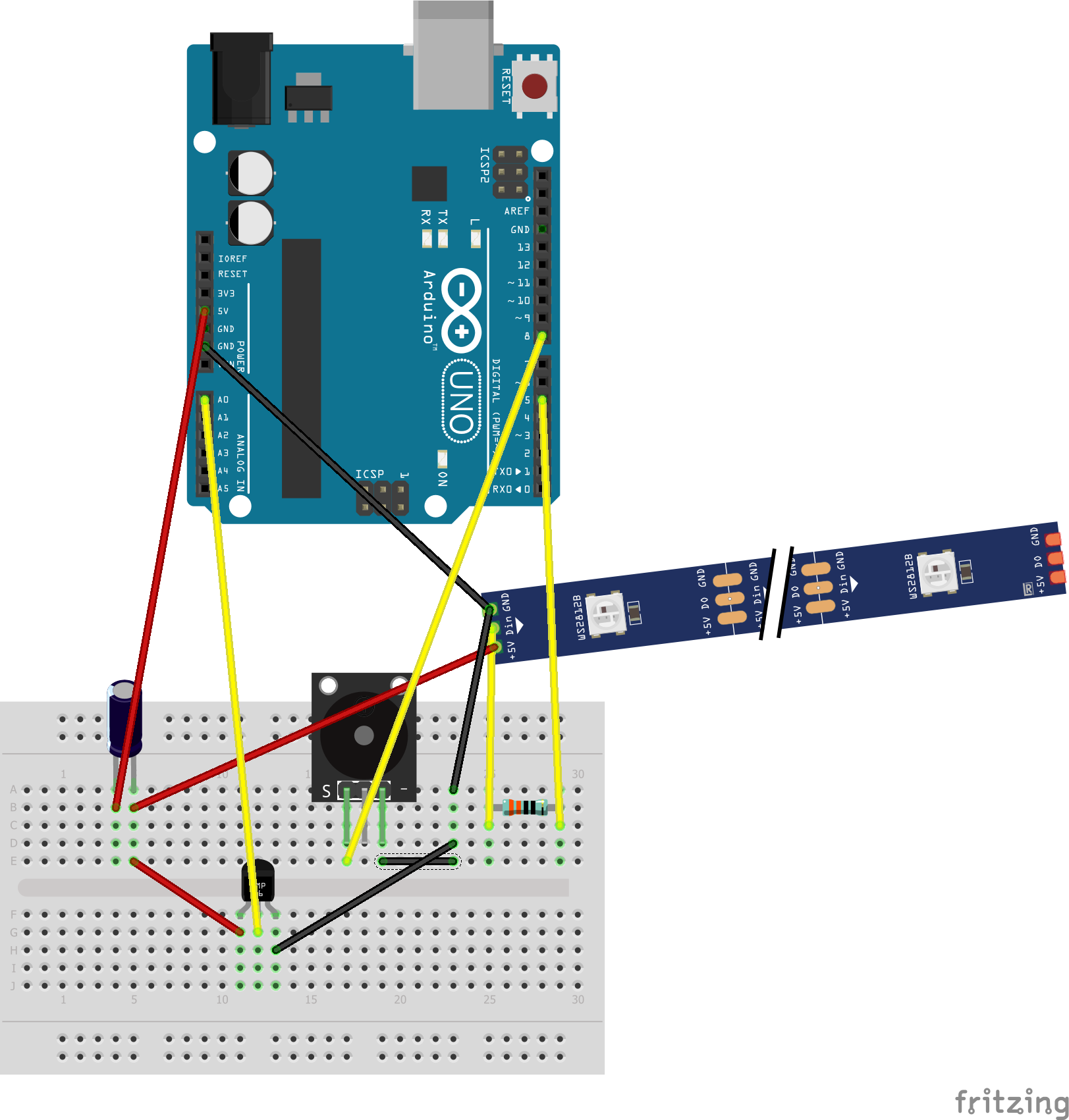
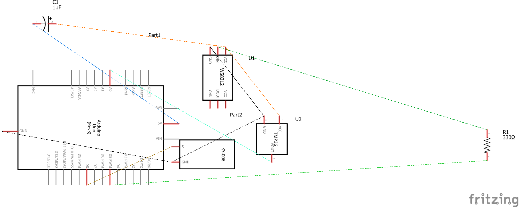
Now you have to arrange everything on a breadboard before you can move it to a PCB board, then decide how to arrange it on the PCB. You can do it however you want; here's two different examples and schematics to help.
If everything is hooked up correctly, the buzzer and the light will both activate when the thermometer detects a temperature higher than your set temperature. If it does not, a blue light will slowly flash instead.
Soldering the PCB Board
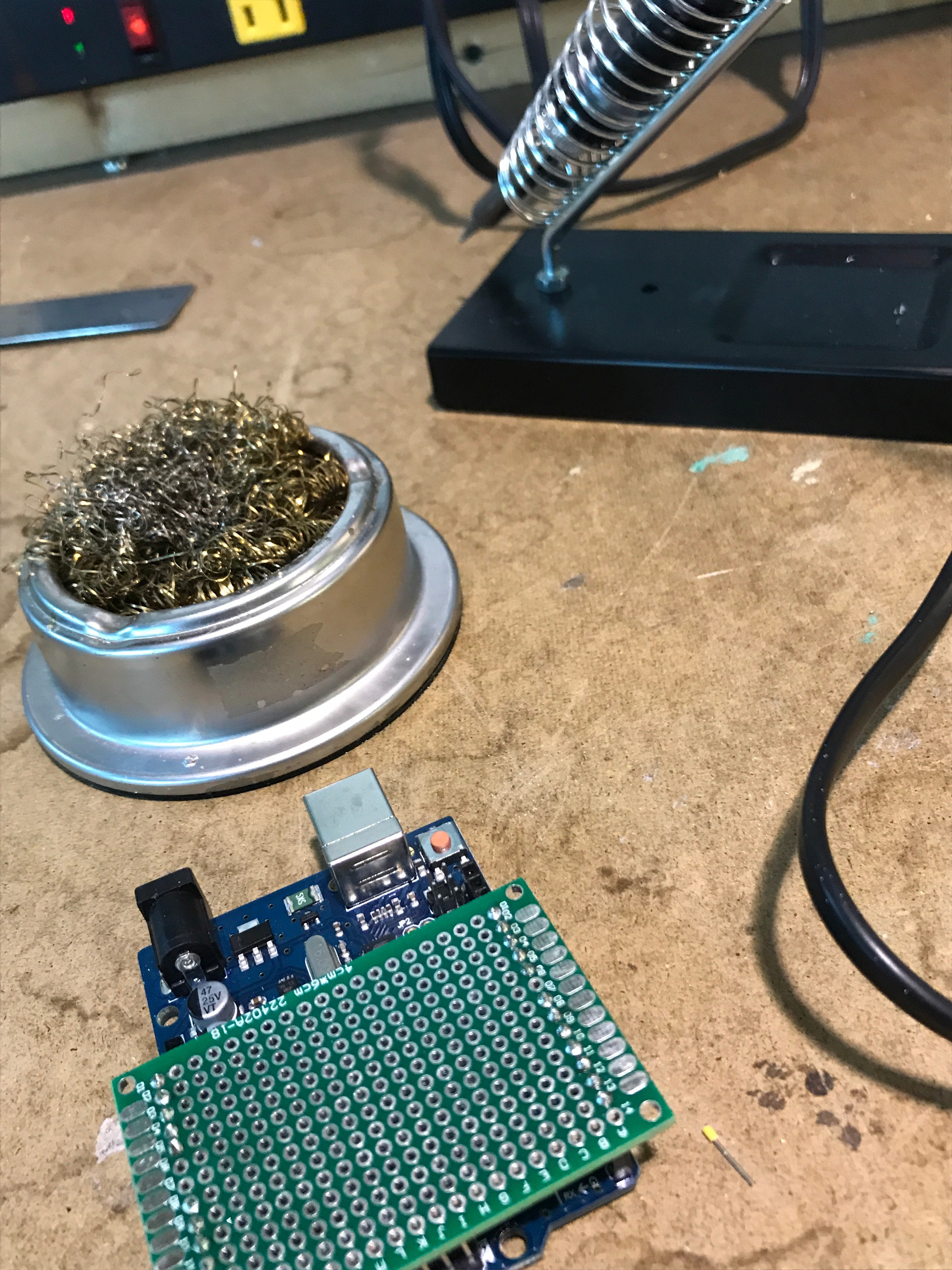.jpg)
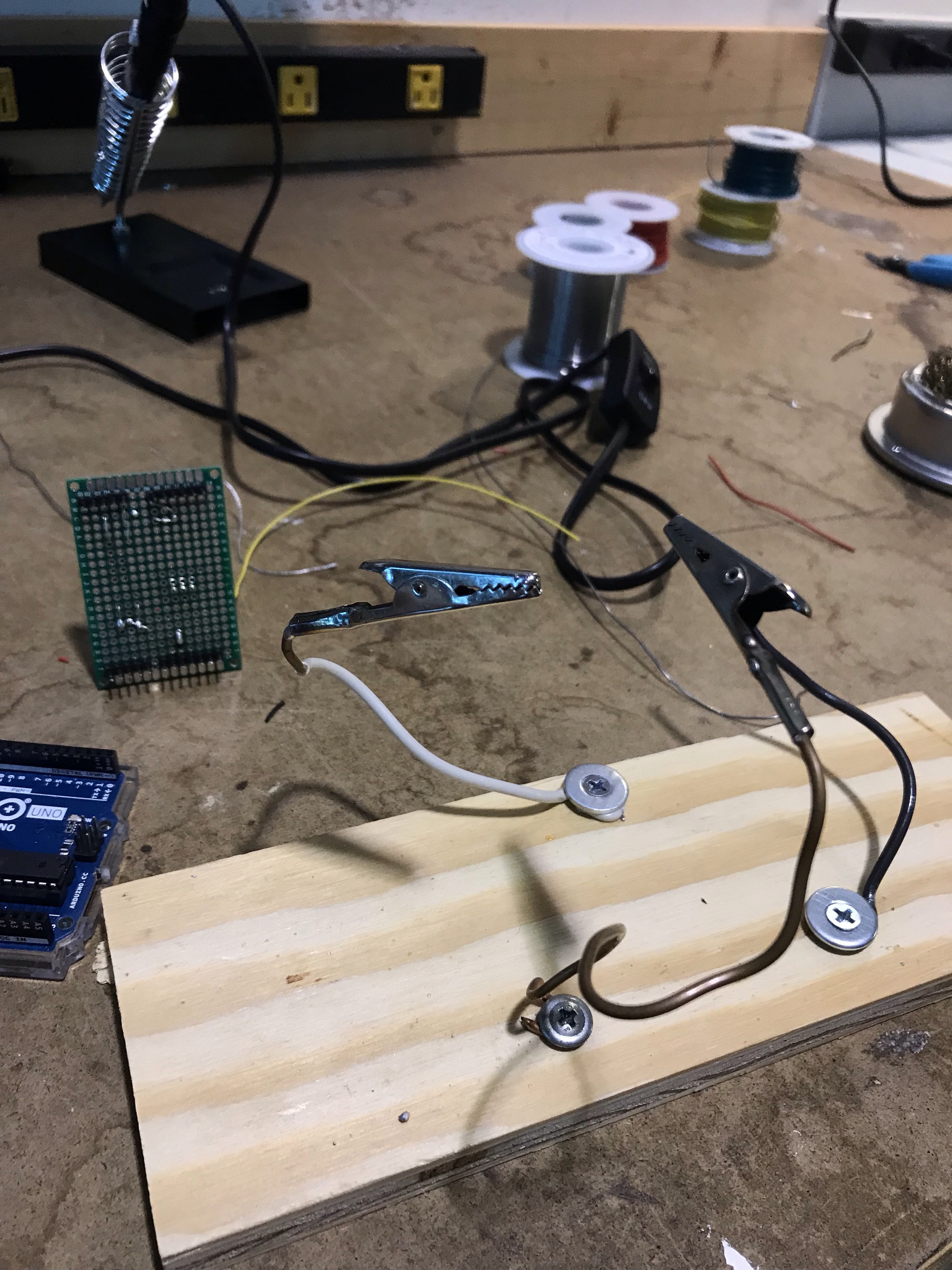.jpg)
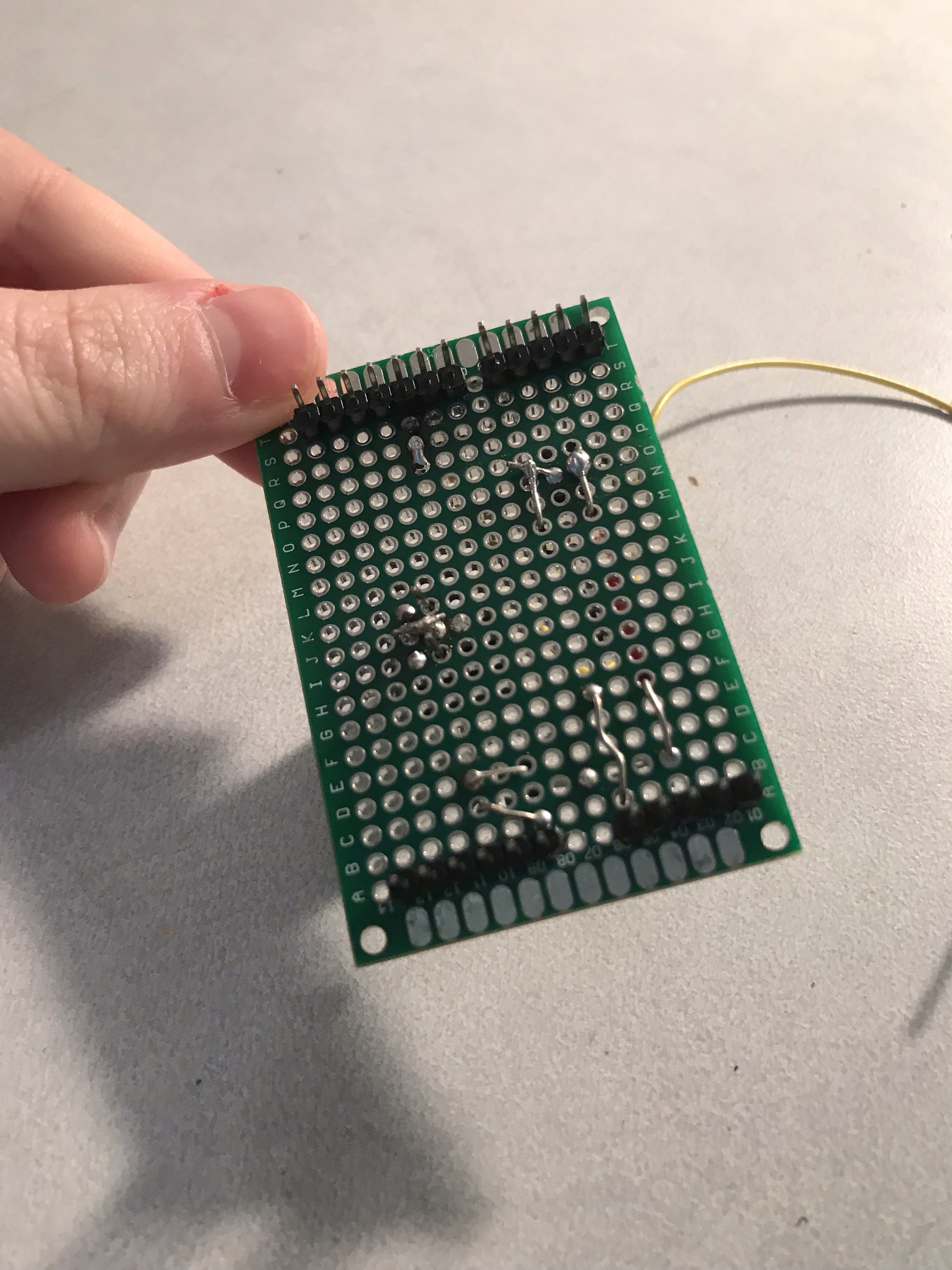.jpg)
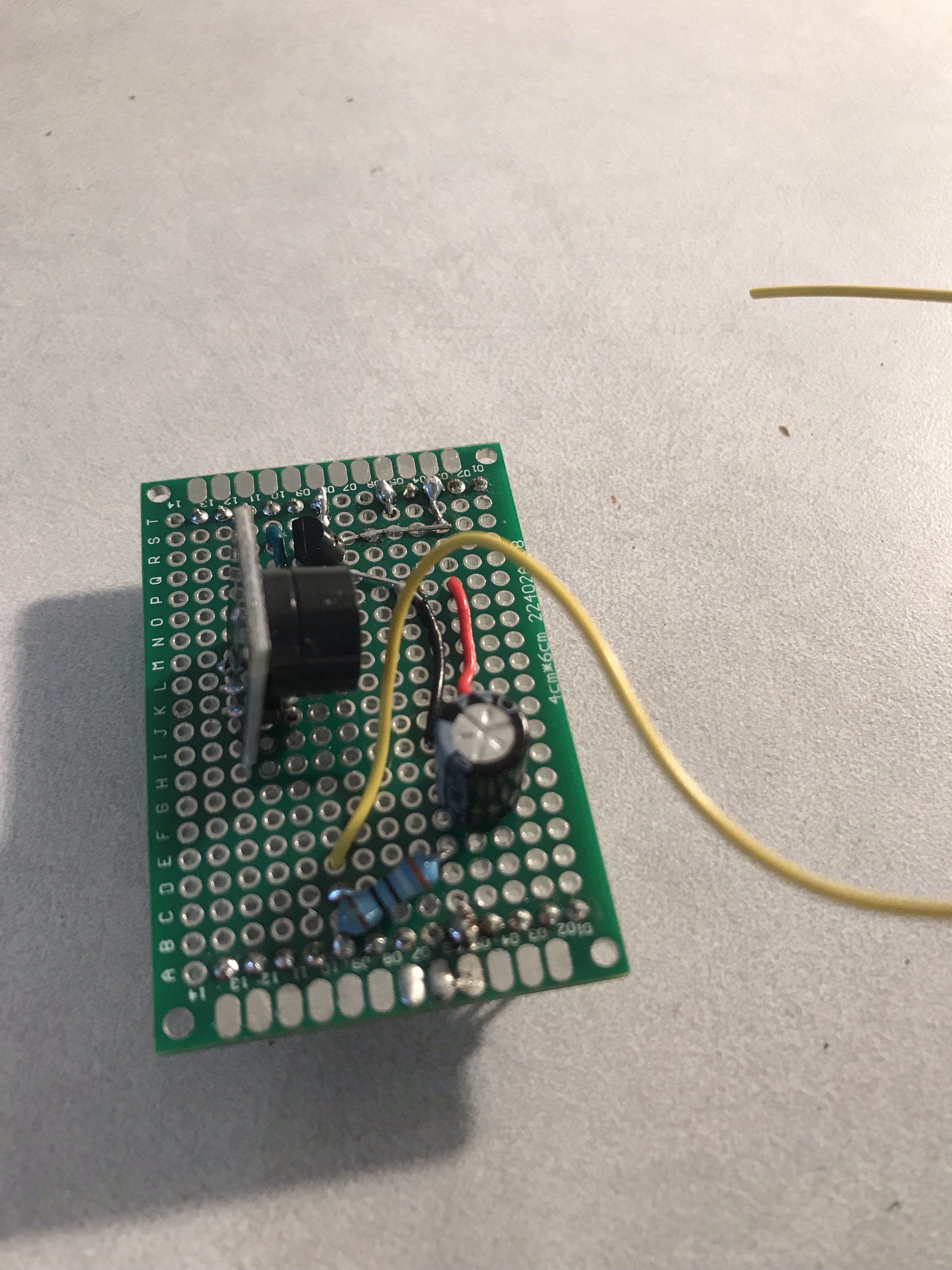.jpg)
![8i7yhp[-;].png](/proxy/?url=https://content.instructables.com/FEB/A8XT/K2VARKH7/FEBA8XTK2VARKH7.png&filename=8i7yhp[-;].png)
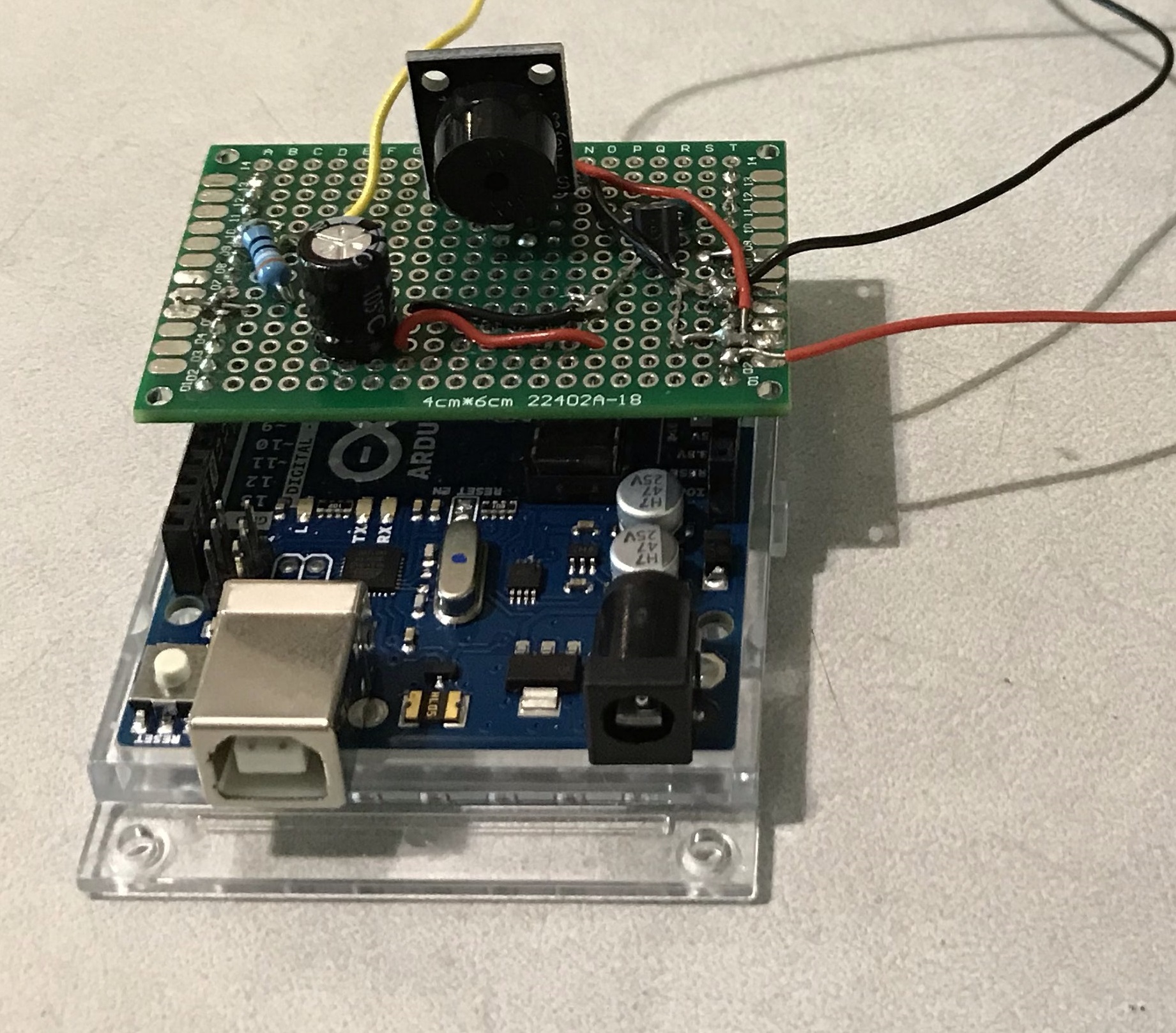.jpg)
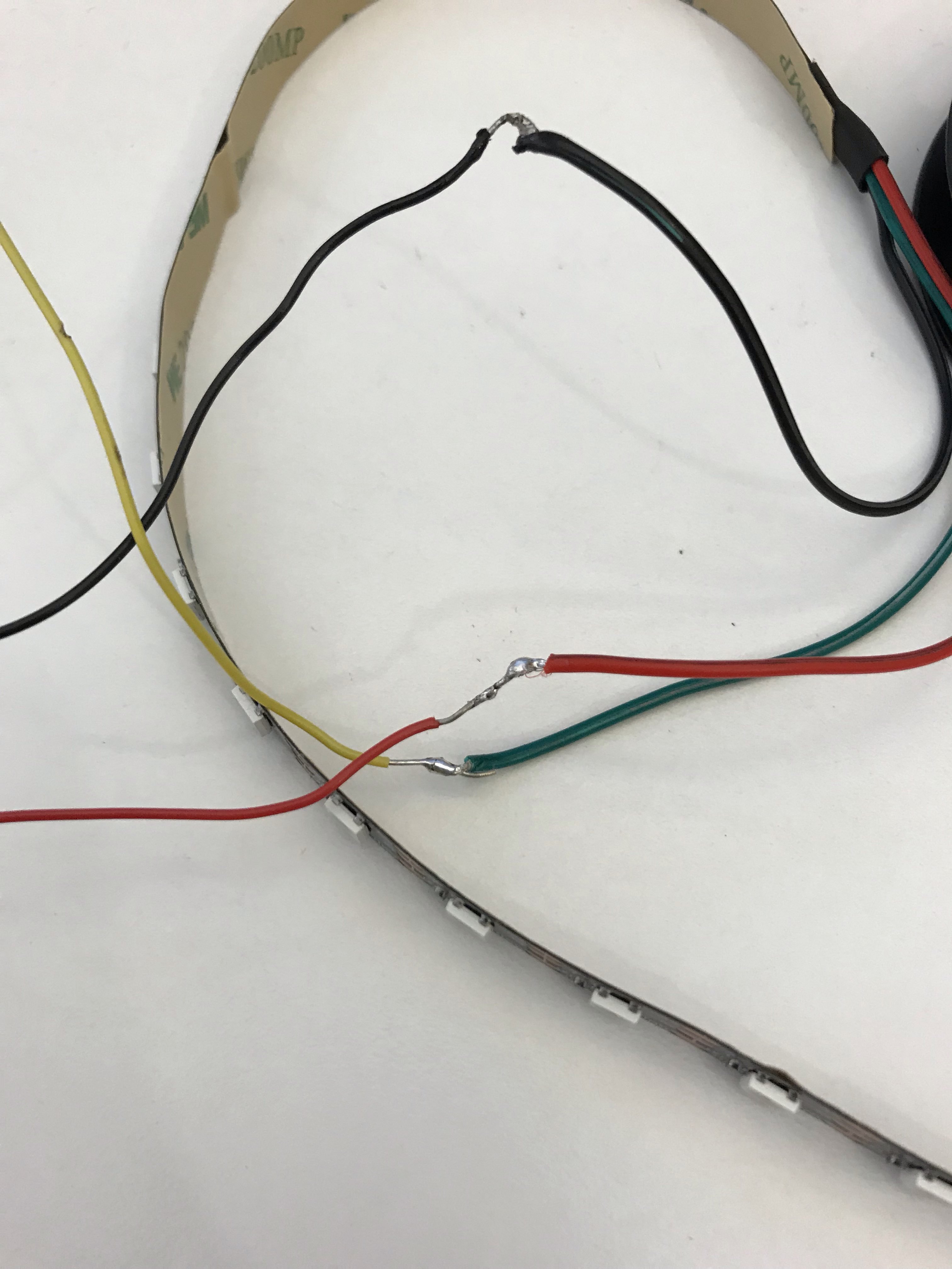
This is the difficult part that is hard to show step-by-step.
First, you need to solder clips onto the board- enough so that they press down into the Arudino slots you need. You want to basically make an Arduino shield that costs much less. With the pin strip soldered in, it should be able to stick on top of an Arduino. Make sure the board actually fits on the Arduino and take notes of which slot each pin goes in to after you've solder them into place.
Use your breadboard as a guide and bend the back of the pins on the capacitor, thermometer, and resistor, soldering and wiring one at a time. Using colored wire makes it easier to find where you need to go; I color coded red for power, black for ground, and yellow for data.
You'll need to strip any wire pieces that go underneath the board (and long stripped solid wire is easy to mistake for solder, so be sure to dispose of it properly!) Leave long wires hanging where you'll attach the light strip wires, the wires for my light strip were made of stranded wire. In order to best solder them, wind the stranded wire around the solid core wire and solder it in place.
Alligator clips help hold the board in place when you need both hands to solder something and brass sponges are good for quickly wiping off the iron.
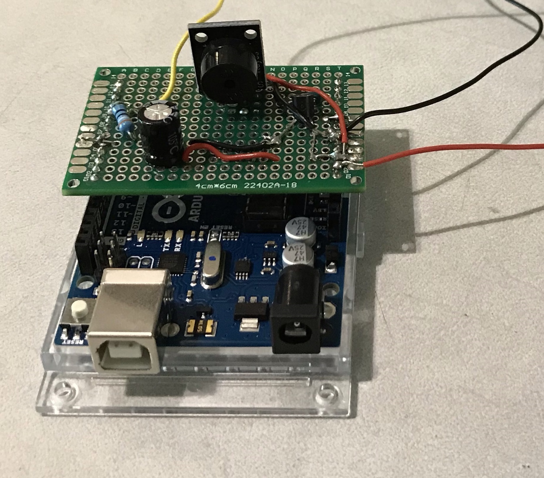
It should look something like the image examples.
While not required, a multimeter helps you check if you've wired something correctly.
It's Done, You Decide Where It Goes!
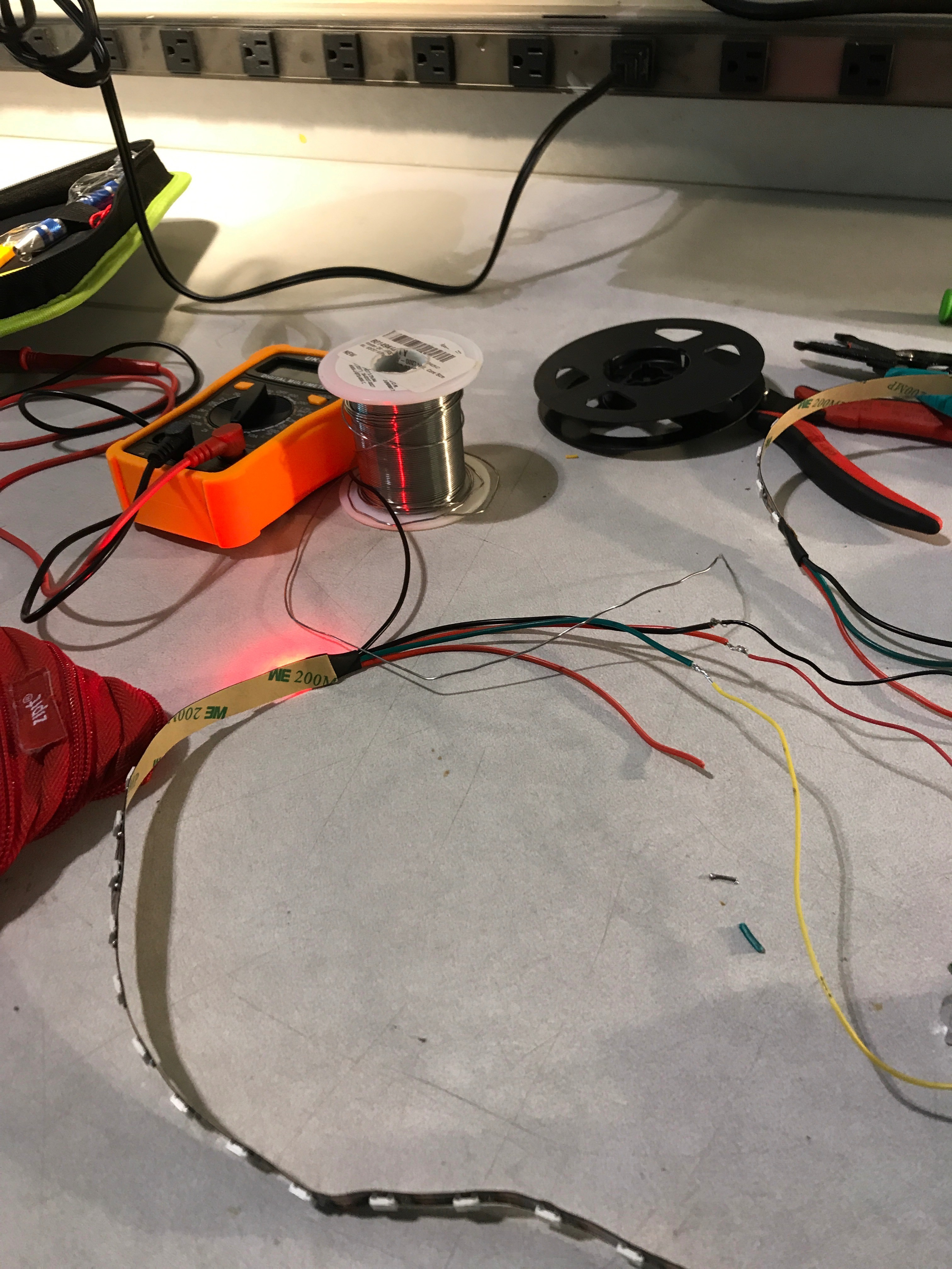
By now, you should have everything completed. At this point, it's up to you to decide where you put your device. For the example, I'm using a 5 volt battery, but long term, you'll want a stronger source of power if you choose to use a large amount of LEDs.
I plan on putting it in a hat, as an example, but you're free to do what you like with your own.